
International Journal of Electrical and Electronics Research ISSN 2348-6988 (online) Vol. 8, Issue 3, pp: (61-68), Month: July - September 2020, Available at: www.researchpublish.com
DESIGN OF BATTERY MANAGEMENT SYSTEM
Harsh Shah1, Sahil Mangaonkar2 , Siddhant Bhatt3
U.G. Student, Electronics1, Electronics and Telecommunication2 , Electronics3 Engineering, Dwarkadas J. Sanghvi College of Engineering, Mumbai, India-400056
Email: harshshah.hs208@gmail.com1, sahilmmangaonkar@gmail.com2 , siddhantbhatt1999@gmail.com3
Abstract: The project reviews the necessity and design of battery management circuitry and also describes tests required for characterization of Li-ion cell. Design and analysis of cell balancing circuitry is discussed. Problem like overvoltage, discharging, SOC(State of Charge) , SOH(State of Health) are encountered. Additionally, the text explains the design of electronic load which can also be used as a battery-charger. The effect of discharging rate on the capacity of a cell is analyzed. It is hoped this design would contribute to sustainable development. We aim to provide a Battery Management Systems for the Electric vehicle Systems and hence aim to do our bit to ease their task.
Keywords: BMS, Battery Monitoring and Management, Master Slave configuration, State of Charge, State of Health, CAN Trans receiver.
1. INTRODUCTION
1.1
Need for Battery Monitoring and Management:
With the continual rise in average global temperatures, an alternative and eco-friendly source of transportation was required. Electric and hybrid-electric vehicles have proved to be efficient and environment friendly in the past decade. The most common power source for these vehicles are Lithium chemistry-based cells. Battery-packs made out of these cells needs continuous monitoring as they are hazardous and explosive in nature when subjected to a hostile environment. Maintenance of these batteries is thus proving to be of paramount importance. Selection of appropriate battery chemistry is a very important factor in deciding the overall performance of the system. From today's perspective, Li-ion chemistry is the battery technology of choice due to its high energy density and power rating and charge/discharge efficiency in pulsed energy flow systems. A Li-ion fails if overcharged, over-discharged or operated outside their safe operating temperature window. For this reason, it requires a Battery Management System (BMS) which will maintain each cell of battery within the safe operating range. At present, numerous automobile firms have developed their BMS's. However, their designs are proprietary. Our goal is to develop a BMS which would serve the purpose of monitoring large battery-packs, with no compromise on the system and user's safety. The design would be open sourced so that the entire community is benefited.
1.1.1Requirements for Battery Monitoring and Management:
Battery Monitoring is important for Li-ion chemistry for ensuring prolonged battery life as well as energy efficiency. The main parameters required for this task are voltage, current and temperature over time. Another important parameter to be taken into consideration is State-Of-Charge (SOC). The operational characteristics and cell life are a strong function of temperature. Abrupt cell temperature changes can indicate cell failure. The below figure illustrates a basic BMS used in a typical Electric Vehicle or a power generation station.
Page | 61 Research Publish Journals
International Journal of Electrical and Electronics Research ISSN 2348-6988 (online)
Vol. 8, Issue 3, pp: (61-68), Month: July - September 2020, Available at: www.researchpublish.com
1.1.2 Implementation:
The project aims to implement a BMS based on a Master-Slave configuration. It would have multiple slaves each monitoring a fixed number of cells in a module. They would all be communicating the master board via a communication protocol. The idea is to ensure the system is reliable and fail-proof. CAN would be used as it is the widely used protocol in the automobile sector. This allows flexibility in the number of slave boards connected in a system. 4 An additional functionality implemented is contactor control. Motor-drives, both AC and DC deploy high capacitance to reduce input ripples. Connecting the battery pack directly to the motor-drive would create an in-rush current, potentially damaging the contactors and the motor-drives. To prevent this, a pre-charge circuitry is implemented which charges the capacitors via a resistor.
2. SYSTEM MODEL / ARCHITECTURE
2.1 Design of Charger-Discharger Circuit:
In order to design a BMS, characteristics of the cell under use must be known. To obtain the cell characteristics, we have designed an electronic load which can discharge with different currents and profiles. The circuit uses a 1 ohm, 10 W equivalent resistor and FET's internal resistance to dissipate cell's energy in the form of heat. Current and cell voltage is monitored and stored.
The circuit uses a STM32F103C8T6 development board for control and monitoring the process. The threshold voltages are set using the keypad prior to the start of discharge cycle. A PID controller is implemented which adjusts the duty cycle to maintain constant discharge current.
When the cell is fully discharged, the process is halted. The cell temperature is monitored continuously so that the effects of temperature on cell characteristics is minimal.
The same set-up is used to charge a battery. The designed circuit can be used to charge batteries rated up-to 50 V with a charging current limit of 10 A. A relay is used to switch the battery between charge and discharge modes. Charger circuit rated up-to 150 V, 20 A is being developed.
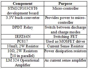
2.1.1 Components used and BMS Master v1.0 PCB:

2.1.2 Limitations:
The designed circuit had the following problems:
Error while current and voltage sensing due to switching.
Improper MOSFET switching.
2.2 Design of BMS Master:
To overcome these issues, a new version was developed. It incorporated the necessary functions of a BMS Master board as well.
Page | 62 Research Publish Journals
Table 2.1: Components used in Charger-Discharger Figure 2.1: Charger-Discharger Circuit
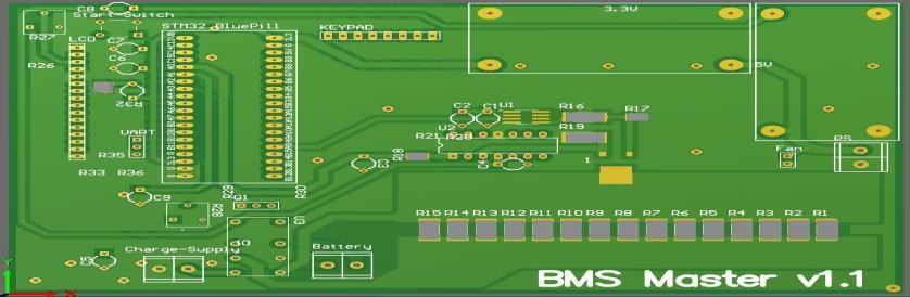
2.2.1 BMS Master v1.1
Figure 2.2: BMS Master v1.1
2.2.2
Modifications:
The switching harmonics which affected current and voltage measurement were eliminated using low pass filters with cut-off frequency as 10 kHz, which is half of the switching frequency. The IRFZ44N was replaced with an IRFR024N MOSFET. It was driven by an IRS2003STRPBF half-bridge driver. This significantly improved the performance.
2.3
Design of BMS Slave:
To understand the basic requirements of a slave board, we reverse engineered the Elithion Lithiumate BMS. After analyzing the boards, we found out it comprises of the following circuit blocks:
Voltage sensing
Temperature sensing

Passive balancing circuit
Isolated communication
PIC micro-controller
2.3.1 BMS Slave v1.0:
Necessary components for isolated communication were not readily available. So we implemented the other four features in our first version of slave board. The circuits were first tested on LTSpice and Proteus. A prototype PCB was designed and manufactured in the labs for preliminary testing. The prototype board had a provision of monitoring and balancing three cells. The circuits were tested multiple times to ensure the design is fail- proof.
2.3.1.1 Components Used and BMS Slave v1.0 PCB:

Table 2.2: Components used in BMS Slave v1.0
2.3.1.2
Limitations:
Figure 2.3: BMS Slave v1.0
The balancing circuit worked perfectly fine, however, at high voltages, the base- emitter voltage exceeded the threshold, causing the transistor to fail. To overcome this, we used an opto-coupler to drive individual transistors with their gatedrain voltage restricted to the maximum cell voltage.
Page | 63 Research
International Journal of Electrical and Electronics Research ISSN 2348-6988 (online) Vol. 8, Issue 3, pp: (61-68), Month: July - September 2020, Available at: www.researchpublish.com
Publish Journals
International Journal of Electrical and Electronics Research ISSN 2348-6988 (online) Vol. 8, Issue 3, pp: (61-68), Month: July - September 2020, Available at: www.researchpublish.com
The above board could monitor only three cells. We designed a new PCB with the ability to monitor up-to 16 cells and got it manufactured from JLC.
2.3.2 BMS Slave v1.1:
2.3.2.1 Components Used and BMS Slave v1.1 PCB:

Table 2.3: Components used in BMS Slave v1.1
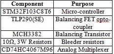
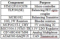
Figure 2.4: BMS Slave v1.1
Instead of using an existing STM32F103C8T6 development board, a minimum system using the same IC was developed. SWD was enabled for programming as well as for debugging.
Additionally, CAN trans receiver was set-up with necessary filters. USB CDC was enabled along with a UART port.
2.3.2.2 Issues encountered:
This being our first experience with STM32 micro-controllers, we were aware of possible issues we might face. However, setting up the micro-controller was extremely difficult. SWD, UART and USB failed to detect the micro-controller on the debugger.
As we had utilized all our micro-controllers, we did not have any other option but to use the development board itself. Another board was developed, with the same architecture, however, used the development board.
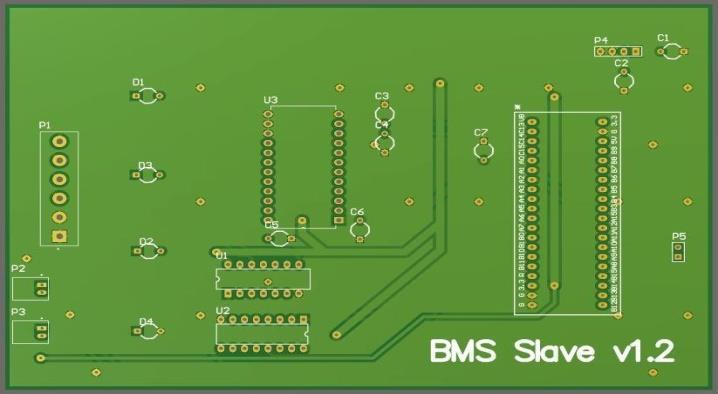
2.3.3 BMS Slave v1.2:
2.3.3.1. Components Used and BMS Slave v1.1 PCB:
Table 2.4: Components used in BMS Slave v1.2
2.3.3.2. Further development:
Figure 2.5: BMS Slave v1.2
Owing to the current scenario, BMS Slave v1.2 could not be tested. However, it definitely provides a good scaled down version of the 16-cell BMS Slave v1.1. Instead of CAN, the board uses an SPI interface to communicate with the BMS Maser.
Implementation of STM32 minimum system is possible, however requires some additional pull-up resistors on SWDIO and SWDCLK. Pulling up BOOT1 pin might help. We could not do the latter due to space constraints.
Research Publish Journals
Page | 64
International Journal of Electrical and Electronics Research ISSN 2348-6988 (online)
Vol. 8, Issue 3, pp: (61-68), Month: July - September 2020, Available at: www.researchpublish.com
3. SYSTEM IMPLEMENTATION
3.1 Development of Battery-Pack:
3.1.1
Cell Selection:
A battery pack is required for testing that the system is working correctly or not. As we mentioned there are various cell chemistries available to choose from to make the battery pack. We had to choose a type that has a Lithium based chemistry, so we decided to use Li-Ion batteries as they widely used in the electronics sector. Even the Li-Ion batteries are available in different form factors but 18650s are the best fit as they have a compact body structure in a cylindrical shape so that they can be stacked in various different ways which makes the battery pack assembly easy for us.
When we were thorough with what type of a cell to select, we had to select which one to use as there are many companies producing this particular type. Due to the availability Samsung’s product line around our location, it was an easy choice for us.
Hence we chose Samsung’s Li-Ion 18650s to be used in our battery pack for testing the BMS system circuit.
3.1.2 Assembly:
The battery pack we were making was for the testing purpose so the configuration we went ahead with 8s2p. This means a pair of cells in parallel was one module and eight such modules connected in series to form a bank of 8s2p.
We used the cell holders for 18650s to mount the cell in a fixed position. First we made eight module of two cells in parallel in which we connected both the cells with an aluminium strip. We heated the aluminium strips and used flux to solder them with the cell ends. After the eight modules were ready in their cell holders we used multistranded wires to provide a series connection. Then we just glued the holders together using a hot glue- gun.
One of the risks was the cells getting damaged while soldering the ends with aluminium strip but we took care that temperature at cell end was below a certain point and the connections were made sure to be proper. With this we completed our DIY test battery pack.
3.2 Cell Characterization:
Cell characterization is the process of identifying the distinguishing parameters, which are unique to a particular cell type and chemistry. They are have high dependencies on external environment, load dynamics and the cell chemistry itself. We used a Samsung ICR 18650-26J 2600mAh Lithium-ion cell for characterization. The following are the important cell parameters required:
3.2.1 State of Charge (SOC):
State-Of-Charge (SOC) determines the energy capacity of battery, i.e. knowing the amount of energy left in battery compared with the energy it had when it was full. SOC estimates whether the cell is charged or discharged and let us know the present state of the battery.
This is estimated by relating the open circuit voltage of the cell to the specific value that is provided by the manufacturer of the cell. Comparing the maximum and minimum voltage value, the present open circuit voltage of the battery gives us the SOC. The open circuit voltage varies with change in temperature, so accordingly after calculating it while considering the temperature variation we can determine the SOC.
3.2.2
Internal Resistance:
Internal resistance is a variable quantity which determines the health of a cell. Temperature changes might cause temporary change in the cell resistance value. Permanent changes in the cell resistance occurs due to internal corrosion which increases gradually as the cell ages. But all these changes are minimal because Li-ion chemistry has new and better electrolyte additives.
3.2.3 State of Health (SOH):
State of Health refers to the overall degradation of a cell. With every charge-discharge cycle, the total capacity of a cell goes on reducing. SOH assists in the calculation of range of a battery pack along with providing a prediction of maintenance or replacement needs.
Page | 65 Research Publish Journals
3.2.4
International Journal of Electrical and Electronics Research ISSN 2348-6988 (online) Vol. 8, Issue 3, pp: (61-68), Month: July - September 2020, Available at: www.researchpublish.com
Cell Characterization using Electronic Load:
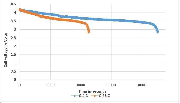
A Li-ion cell was fully charged and allowed to stabilize for one hour. The cell was subjected to constant current discharge of 0.4 C and 0.75 C. The terminal voltage and charge discharged Ah were monitored until the cell reached the lower voltage threshold.
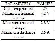
Table 3.1: Cell threshold parameters
3.2.5 Results: The following are the outcomes of the tests performed:
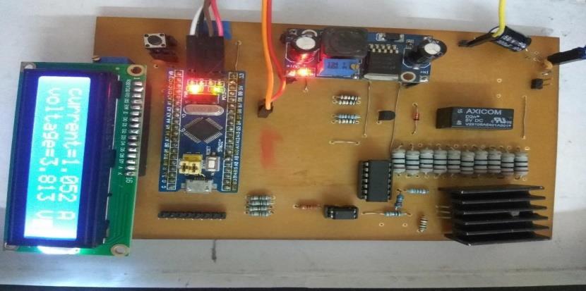
Figure 3.1: Cell under test
Figure 3.2: Discharge curves
Table 3.2: Calculation of Relative Capacities
It is evident from the tests that the capacity of a cell is a function of discharge rate. The total capacity of 2.6 Ah as specified in the datasheet.
3.3 Slave Circuit Design and Testing:
During charging and discharging cycles of batteries, the voltage values for individual cells may vary. This leads to unequal voltage levels in cells all around the battery pack, which may further degrade the battery life. Hence, cell balancing is an important factor that helps us use the battery efficiently.
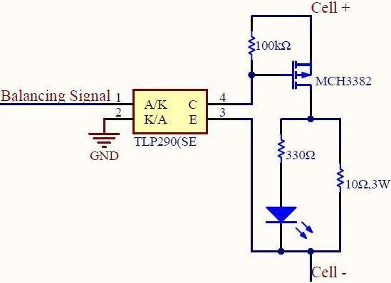
The balancing circuit involves three major components: a 10-ohm bleeder resistor, a P-channel MOSFET and an optocoupler to drive the P-channel MOSFET. The circuit is tested to ensure that the FET is operated within its capabilities. The 100k-ohm pull-up resistor ensures that the FET is not turned on due to noise. When an imbalance is detected, the opto-coupler turns on the FET by pulling the gate low.
Page | 66 Research
Publish Journals
International Journal of Electrical and Electronics Research ISSN 2348-6988 (online) Vol. 8, Issue 3, pp: (61-68), Month: July - September 2020, Available at: www.researchpublish.com
Figure 3.3: Balancing Circuitry
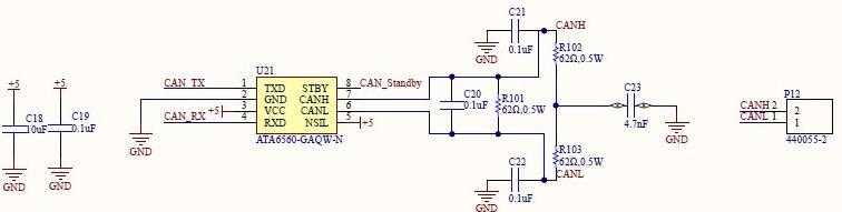
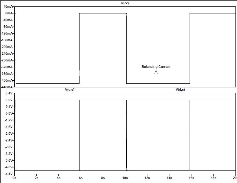
Figure 3.4: LTSpice Simulation Results
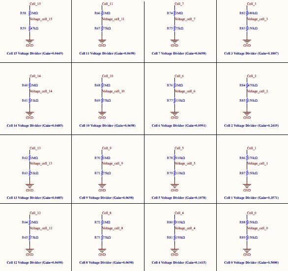
Figure 3.5: CAN Implementation
CAN is the widely used communication protocol, especially in Automobile sector. However, its realization requires some additional measures like adding noise immunity on as well as off the PCB. Use of twisted wires and industrial grade connectors were suggested.
Figure 3.6: Voltage Dividers for Terminal Voltage Sensing
Page | 67 Research Publish Journals
International Journal of Electrical and Electronics Research ISSN 2348-6988 (online) Vol. 8, Issue 3, pp: (61-68), Month: July - September 2020, Available at: www.researchpublish.com
4. CONCLUSION
A Battery Management System (BMS) can be developed with various different configurations. However, a master- slave configuration suits well with 18650 or 21650 cylindrical cells owing to their limited capacity and higher number of cells in a battery pack. A BMS must possess functionality to control charger, contactors, cooling systems and ground isolation protection. CAN or MODBUS work well with master- slave configuration BMS’s and can be easily added into an automobile’s electrical system. Characterizing a cell is an integral part of BMS development. The project involves a PWM based closed loop discharge circuit for this purpose. The test conveys an important result that the capacity of a cell is a function of the discharge rate. This is an important parameter which effects SOC estimation in a dynamic condition like an Electric Vehicle. Additionally, the same discharge circuit can be further modified into a charger circuit by using a half- bridge configuration. The high-side transistor would be operational while charging and the low-side transistor while discharging.
ACKNOWLEDGEMENTS
Authors are greatful to Our Mentor Prof Vivek Nar and Proj Sejal kadam for providing Technical assistance. Their mentoring and total guidance helped us at every stage for this paper.And this paper would not have possible without their great help.We thank our collègues who provided advice and guidance that greatly contributed to the development of the paper. Also the way everyone found our mistakes and corrected it is of great help to us.
REFERENCES
[1] Y. Kim, S. Yun and J. Lee, "SOC estimation and BMS design of Li-ion battery pack for driving," 2017 14th International Conference on Ubiquitous Robots and Ambient Intelligence (URAI), Jeju, 2017, pp. 216- 218.
[2] P. Savanth and Shailesh K.R., "Reduction of parameters in a Lithium ion cell model by experimental validation of relationship between OCV and SOC," 2016 Online International Conference on Green Engineering and Technologies (IC-GET), Coimbatore, 2016, pp. 1-5.
Page | 68 Research Publish Journals