
International Journal of Civil and Structural Engineering Research ISSN 2348-7607 (Online) Vol. 8, Issue 2, pp: (1-10), Month: October 2020 - March 2021, Available at: www.researchpublish.com
Finite Element Analysis of RC Slabs Subjected to Blast Loading
Mennatullah Talaat1, Ebtisam Yehia2, Sherif A. Mazek3, Magdy M. M. Genidi4 , Alaa
G. Sherif5
1Teaching Assistant, Construction and building Department, AASTMT, Cairo, Egypt
2Assistant Prof. of Structural Engineering, Faculty of Engineering at AASTMT, Cairo, Egypt 3Prof. of Civil Engineering, Military Technical College, Cairo, Egypt.
4Assoc. Prof. of Structural Engineering, Faculty of Engineering at Mataria, Helwan University, Cairo, Egypt 5Prof. of R.C Structures, Faculty of Engineering at Mataria, Helwan University, Cairo, Egypt.
Abstract: In this paper, the response of reinforced concrete slabs subjected to blast loading under variable mass of TNT and different reinforcement configuration will be discussed. The study was carried out using the finite element program (ABAQUS) by using 3 different models (concrete slab without reinforcement, concrete slab with single reinforcement and concrete slab with double reinforcement).The plastic behavior of steel reinforced bars and concrete has been incorporated through Johnson-cook model and concrete damage plasticity model respectively. The results obtained from concrete slab models are in terms of Von-Mises stresses, deflection and concrete damage against varying mass of TNT. The results indicate that using double reinforced mesh has great influence on reinforced concrete slabs to withstand blast loads.
Keywords: Blast loading, Reinforced Concrete Slabs, ABAQUS, Stresses, Deformation, Damage.
I. INTRODUCTION
Nowadays, the damage of structures due to explosion has increased as a result of increase in number and intensity of terrorist activities, accidents and explosions so the effect of blast loads on the structure is a serious matter of concern that should be taken into consideration in the design process It is necessary to first quantify the effects of explosions in order to design structures which are able to withstand the blast loads. [11]They reported that the explosive load on buildings can be simplified into triangle impulse pressure in order to make the simulation easier and then a one-way RC slab against the explosive load can be used as an example to be tested by the powerful FEM software- ABAQUS to simulate numerically the behaviors of the slab. The failure modes for the Reinforced concrete slab under the different loads are presented by the comparison of analysis outcomes for the same impulsive but different duration time and peak pressure of explosive loading. [6]They explained the analysis and design of structures subjected to blast loads. They presented a comprehensive overview of the effects of explosion on structures. [7] They proposed an analytical method by which the punching was estimated by comparing the dynamic shear demand and capacity. The approach takes in account the impulsive behavior of the member leading to a higher punching capacity and gives preferable predictions than using existing formulae for punching. The analytical equations were propped by numerical explicit finite element models giving useful information of crack development, deflections and dynamic reactions. [10] They carried out a numerical simulation on reinforced concrete slab against blast loading to demonstrate the accuracy of the finite element based on using ABAQUS. The parameters studied subjected to surface blast were weight of TNT and boundary conditions. Based on the detailed literature survey , it is observed that most studies focused on simple experiments on slabs subjected to blast loads, however numerical investigations on slabs under blast loading has been found limited. Also the response of reinforced concrete slabs against blast loading under varying mass of TNT hasn’t been studied. In the present study, the simulation has been carried out on 3 different models (concrete slab without reinforcement, concrete slab with single reinforcement and concrete slab with double reinforcement) against blast loading through the finite element program (ABAQUS) under varying mass of TNT. The plastic behavior of steel reinforced bars and concrete has been incorporated through Johnsoncook model and concrete damage plasticity model respectively.
Page | 1 Research Publish Journals
International Journal of Civil and Structural Engineering Research ISSN 2348-7607 (Online) Vol. 8, Issue 2, pp: (1-10), Month: October 2020 - March 2021, Available at: www.researchpublish.com
II. CONSTITUTIVE MODELLING
The plastic behavior of concrete has been defined through concrete damage plasticity model and the model included compressive and tensile behavior. The elastic and plastic behavior of steel reinforcement bars have been defined using Johnson-cook model includes the effect of state of stress, temperature and strain rate. The units used in ABAQUS [1] are Length (m), mass (Kg), Pressure (Pa) and time (seconds).
A. Damage Plasticity Model For Concrete
In finite element modelling, the plastic behavior of concrete was defined by using concrete damage plasticity model (CDP) providing a general capability for modelling concrete and other quasi-brittle materials.
The plastic-damage model was formed of plasticity theory in which a plastic damage variable 'K' was defined which increases if plastic deformation takes place .Moreover, the plastic damage variable is limited to a maximum value and the attainment of this value at a point of the solid represents total damage, which can be interpreted as the formation of a macroscopic crack.
The variable 'K' is non-dimensional and its maximum value is one. The concrete damaged plasticity model is a continuum, plasticity based, damage model for concrete. The model supposed that the two main failure mechanisms are compressive crushing and tensile cracking of the concrete material.
The evolution of the yield surface was controlled by two hardening variables which are linked to failure mechanisms under compression and tension loading, namely and are compressive and tensile equivalent plastic strains, respectively. The damage variables from zero to one, where zero act as the undamaged material and one act as the total loss of strength. The stress strain relations under uniaxial compression and tension loading are given by the following equations where is the initial (undamaged) modulus of elasticity of the material: ) ( ) and ) ( )
Where and are tension damage variables and compression damage variables, respectively [8]. The concrete damaged plasticity model parameters such as tension and compression damage variables are shown in Table 2 and 3.
The ratio between initial equi-biaxial compressive yield stress to initial uniaxial compressive yield stress .i.e. was considered as 1.16 [4, 8]. The compressive strength of concrete was considered 20 MPa and passion ratio of the concrete was assumed equal to 0.18. The parameters for CDP model other than damage variables are shown in Table 1
Table 1: Concrete damaged plasticity (CDP) model values for concrete Parameter value Mass Density (ρ ) (Kg/ ) 2400 Young’s Modulus (E) (Pa) 24× Poisson’s Ratio 0.18 Dilation Angle 30 Eccentricity 1 1.16 K 0.666 Viscosity parameter 0.1
Table 2: Compression damage values for CDP Yield Stress (Pa) Inelastic Strain Damage Parameter 20× 0 0 15× 0.0011 0.2 12× 0.004 0.24
Page | 2 Research Publish Journals
International Journal of Civil and Structural Engineering Research ISSN 2348-7607 (Online) Vol. 8, Issue 2, pp: (1-10), Month: October 2020 - March 2021, Available at: www.researchpublish.com
Table 3: Tension damage values for CDP
Yield Stress (Pa) Cracking Strain Damage Parameter
3.3× 0 0 3.2× 0.003 0.15 3.1× 0.005 0.21 3 × 0.007 0.28 2.95× 0.01 0.3
B. Johnson Cook Model For Reinforcement
The flow and fracture behavior of projectile and target material was predicted employing the Johnson cook elastoviscoplastic material model [5] available in ABAQUS finite element code[1]. The material model was based on the vonMises yield criterion and associated flow rules. It contained the effect of linear thermo-elasticity, yielding, plastic flow, isotropic strain hardening, strain rate hardening, softening due to damage and adiabatic heating. [5] extended the failure criterion proposed by [2] by banding together the effect of strain path, strain rate and temperature in the fracture strain expression and stress triaxiality. The fracture criterion was based on the damage evolution when the damage parameter exceeds one, the damage of the material occurred. The strain at failure was subordinated on a non-dimensional plastic strain rate, a dimensionless pressure-deviatoric stress ratio, (between the mean stress and the equivalent von-Mises stress) and the non-dimensional temperature.
The stress-strain relationship no longer efficiently represents the material behavior when material damage occurred, [1] The usage of stress-strain relationship beyond ultimate stress introduces a strong mesh dependency based on strain localization. Hillerborg's fracture energy criterion had been applied to minimize mesh dependency by considering stressdisplacement response after the damage initiation. The steel section was assigned Fe250 and the ultimate tensile strength was 250MPa which was nearly equivalent to the ultimate tensile strength proposed by [3].The material properties of steel bars have been shown in Table 4 and 5.
Table 4: Material model values for steel bars
Parameter value Mass Density (ρ ) (Kg/ ) 7850
Young’s Modulus (E) (Pa) 203× Poisson’s Ratio 0.33
Table 5: Johnson Cook Damage model values for steel bars
Parameter value
Yield stress constant (A) (Pa) 304.33× Yield stress constant (B) (Pa) 422.007× Strain hardening constant (n) 0.345 Thermal softening constant (m) 0.87
Fraction Strain Constant
d1 0.1152 d2 1.0116 d3 -1.7684 d4 -0.05279 d5 0.5262
Melting Temperature 1800 Transition Temperature 293 Viscous effect ( C ) 0.0156
Page | 3 Research Publish Journals
International Journal of Civil and Structural Engineering Research ISSN 2348-7607 (Online) Vol. 8, Issue 2, pp: (1-10), Month: October 2020 - March 2021, Available at: www.researchpublish.com
III. VERIFICATION MODEL
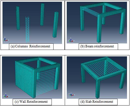
In order to verify the used model, results are compared to the investigation carried out by [9]. The numerical investigation was made on reinforced concrete structures against blast loading through finite element code ABAQUS/CAE. The size of building was considered 3×3×3m and whereas the cross section of beam and column was 0.3m, arbitrary. The thickness of roof Slab was 0.12 m, whereas the four reinforced concrete wall on each face thickness was 0.2m. The plastic behavior of concrete and steel reinforced bars has been defined through concrete damage plasticity model and Johnson-cook model respectively. The main reinforcement for beam and column was 4 bars of 12mm diameter. The stirrups were 8 mm diameter and spaced each 200mm. The steel reinforcement of concrete wall of all four sides was 10mm diameter having spacing of 180mm on both longitudinal and transverse direction of single mat. The Slab reinforcement was 8 mm diameter spaced each 225mm on both directions.as shown in fig.1 (a,b,c,d).
Figure
1: Details of Monolithic RC building used for verification
(a)Stresses of Concrete compared with [9] (b)Stresses of Steel compared with [9]
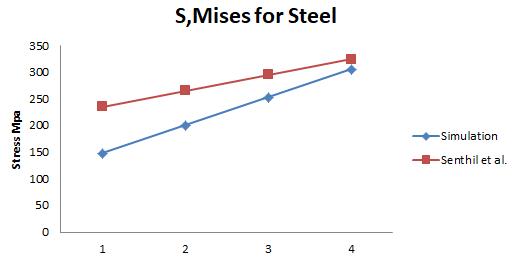
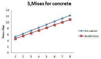
Figure 2: Results compared with [9].
The results of the simulation were compared to [9]. The responses of structural elements were studied in terms of vonMises stresses, deflection and compression and tension damage of concrete. The results obtained from the simulation using ABAQUS/Explicit was in agreement to the model made by [9].as shown in fig.2 (a,b).
Page | 4 Research Publish Journals
International Journal of Civil and Structural Engineering Research ISSN 2348-7607 (Online) Vol. 8, Issue 2, pp: (1-10), Month: October 2020 - March 2021, Available at: www.researchpublish.com
IV. FINITE ELEMENT MODELLING OF SLABS
The finite element models were performed using ABAQUS/CAE. The first model was concrete slab without reinforcement. The dimension of slab was 1×1m and the thickness of slab was 100 mm as shown in fig.3(a). The second model was concrete slab with single reinforcement mesh having same concrete dimensions as the first model. The Slab reinforcement was 8 mm diameter spaced each 200mm on both directions and the cover is 20 mm as shown in fig.3(b). The third model was concrete slab with double reinforcement mesh having same concrete dimensions as the first model. The Slab reinforcement was 8 mm diameter spaced each 200mm on both directions top and bottom and the cover is 20 mm as shown in fig.3(c).

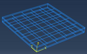
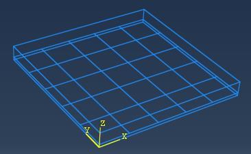
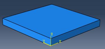
(a)First Model (concrete Slab without Reinforcement)
(b)Second Model (concrete Slab with Single Reinforcement)
Figure 3: Different FE Slab Models.
(c)Third Model (concrete Slab with Double Reinforcement)
The geometry of the concrete was modeled as solid deformable element and steel reinforcement was modeled as wire deformable element. The concrete Slab was meshed using structural elements of 8 noded hexahedral linear brick element and steel reinforcement was meshed with linear truss element .The mesh size was 20 mm for both concrete and steel. The blast origin was kept 1 m from slab center. The analysis was classified into 20 frames within a time frame of 0.08 second.
The interaction between concrete and steel was modeled using constraint embedded region option available in ABAQUS/CAE. The concrete was selected as host region and the steel as embedded region .The blast load was defined using interaction module available in ABAQUS. The surface blast load was formed using CONWEP definition and the surface blast was allocated with the help of two reference point which was assigned based on standoff distance from point of response .The boundary condition is pinned surrounding the slab. The simulations were carried out against different charges of TNT 3,5,10 Kg. with fixed standoff distance 1m.
V. RESULTS AND DISCUSSION
The behavior of reinforced concrete slabs in terms of Von-Mises stresses, deflection and concrete damage against varying mass of TNT is discussed in this section.
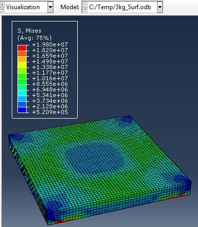
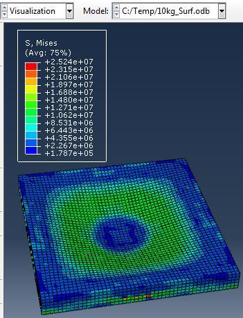
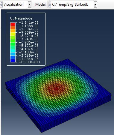
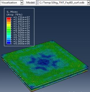
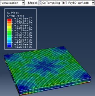
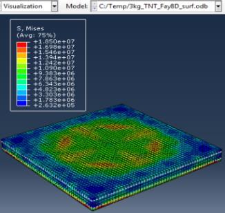
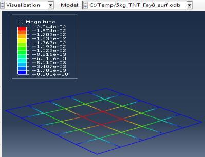
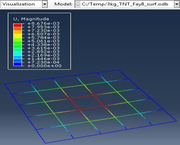
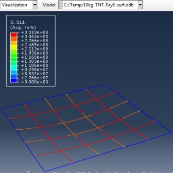
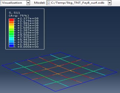
The simulations were carried out for the first model (concrete slab without reinforcement) against varying mass of TNT (3, 5, 10 kg) at constant standoff distance 1m.
Type (a) 3kg TNT
(c) 10kg TNT Stresses on Concrete
(b) 5kg TNT
Page | 5 Research Publish Journals
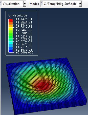
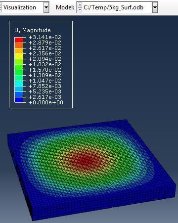
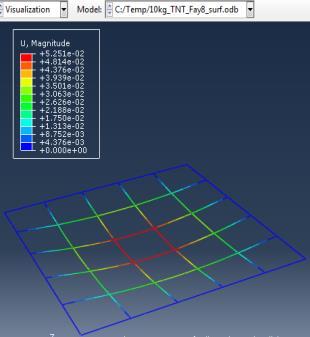
Deflection of concrete
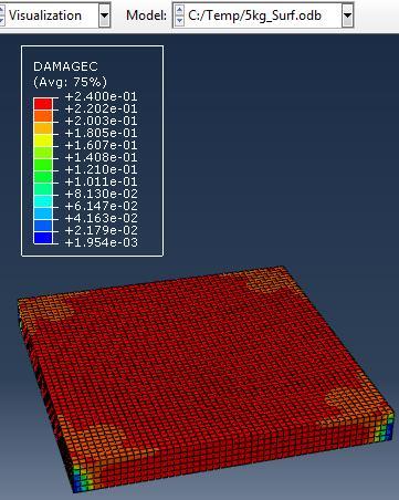
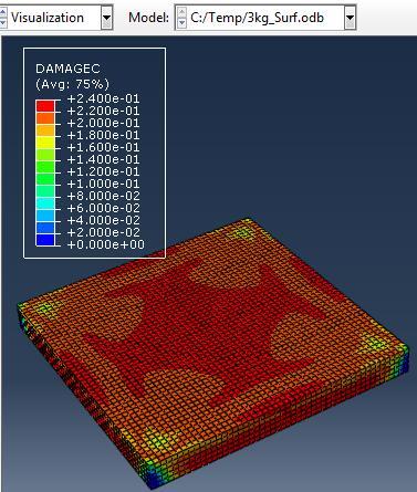
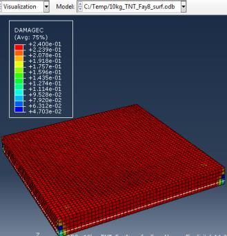
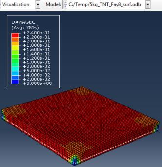
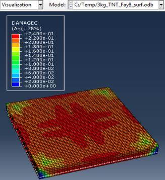
Damage of concrete
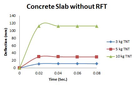
The maximum Von-Mises stresses (S, Mises) of concrete slab against blast load of 3,5,10 Kg mass TNT was 19.8, 22.82 and 25.24 Mpa respectively. The maximum deflection (U,magnitude) of concrete slab against blast load of 3,5,10 Kg mass TNT was 12.4, 31.4 and 114.7 mm respectively. The maximum compression damage (Damagec) of concrete slab against blast load of 3,5,10 Kg mass TNT was 0.24 for all charges.as shown in fig.4 (a,b,c).
The simulations were carried out for the second model (concrete slab with single reinforcement) against varying mass of TNT (3, 5, 10 kg) at constant standoff distance 1m.


Type (a) 3kg TNT (b) 5kg TNT (c) 10kg TNT
Stresses on Concrete
Deflection of concrete
Vol.
Issue
www.researchpublish.com Page | 6 Research Publish Journals
International Journal of Civil and Structural Engineering Research ISSN 2348-7607 (Online)
8,
2, pp: (1-10), Month: October 2020 - March 2021, Available at:
Figure 4: Results of First Model (concrete slab without Rft) with varying mass of TNT
Stresses on steel Deflection of steel Damage of concrete
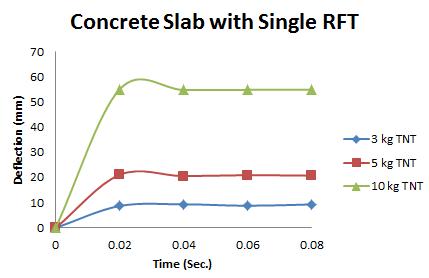
Figure 5: Results of Second Model (concrete slab with single Rft) against varying mass of TNT
The maximum Von-Mises stresses (S, Mises) of concrete against blast load of 3,5,10 Kg mass TNT was 15.52, 16.51 and 17.46 Mpa respectively and the maximum Von-Mises stresses (S, Mises) of steel against blast load of 3,5,10 Kg mass TNT was 59.87, 237.7 and 331.9 Mpa respectively .The maximum deflection (U,magnitude) of concrete slab against blast load of 3,5,10 Kg mass TNT was 9.5, 22.13 and 57.5 mm respectively and the maximum deflection (U,magnitude) of steel against blast load of 3,5,10 Kg mass TNT was 8.67, 20.44 and 52.5 mm respectively. The maximum compression damage (DamageC) of concrete slab against blast load of 3,5,10 Kg mass TNT was 0.24 for all charges. As shown in fig.5 (a,b,c).
The simulations were carried out for the third model (concrete slab with double reinforcement) against varying mass of TNT (3,5,10 kg) at constant standoff distance 1m.
Type (a) 3kg TNT (b) 5kg TNT (c) 10kg TNT
Stresses on Concrete
Page | 7 Research Publish Journals
International Journal of Civil and Structural Engineering Research ISSN 2348-7607 (Online) Vol. 8, Issue 2, pp: (1-10), Month: October 2020 - March 2021, Available at: www.researchpublish.com
Deflection of concrete Stresses on steel Deflection of steel Damage of concrete
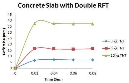
Figure 6: Results of the third Model (concrete slab with double Rft) with varying mass of TNT

The maximum Von-Mises stresses (S, Mises) of concrete against blast load of 3,5,10 Kg mass TNT was 18.5, 18.19 and 17.31 Mpa respectively and the maximum Von-Mises stresses (S, Mises) of steel against blast load of 3,5,10 Kg mass TNT was 50.3, 164.8 and 313.7 Mpa respectively . The maximum deflection (U,magnitude) of concrete slab against blast load of 3,5,10 Kg mass TNT was 7.39, 16.07 and 37.9 mm respectively and the maximum deflection (U,magnitude) of steel against blast load of 3,5,10 Kg mass TNT was 6.91, 15.11 and 36.06 mm respectively. The maximum compression damage (DamageC) of concrete slab against blast load of 3,5,10 Kg mass TNT was 0.24 for all charges. As shown in fig.6 (a,b,c).
Page | 8 Research Publish Journals
International Journal of Civil and Structural Engineering Research ISSN 2348-7607 (Online) Vol. 8, Issue 2, pp: (1-10), Month: October 2020 - March 2021, Available at: www.researchpublish.com
International Journal of Civil and Structural Engineering Research ISSN 2348-7607 (Online) Vol. 8, Issue 2, pp: (1-10), Month: October 2020 - March 2021, Available at: www.researchpublish.com
Figure 7: Response of First Model under varying mass
of
TNT Figure 8: Response of Second Model under varying mass of TNT
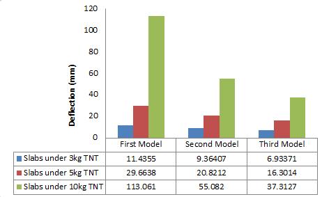
The relation between the deflection and time for the first model (concrete slab without Rft) under different charges of TNT is shown in fig.7. The relation between the deflection and time for the Second model (concrete slab with single Rft) under different charges of TNT is shown in fig.8. The relation between the deflection and time for the Third model (concrete slab with double Rft) under different charges of TNT is shown in fig.9. It was detected that the deflection decreases by 23%,30%,50%from concrete slab without reinforcement model to concrete slab with single reinforcement against 3,5,10kg TNT, respectively. In addition to, the deflection decreases by 22%,27%,36% from concrete slab with single reinforcement model to concrete slab with double reinforcement against 3,5,10kg TNT, respectively. As shown in fig.10.
It was detected that the stresses of concrete decreases by 22%,28%,30%from concrete slab without reinforcement model to concrete slab with single reinforcement against 3,5,10kg TNT, respectively. Also, the stresses of concrete increase by 16% while the stresses of steel decrease by the same percentage from concrete slab with single reinforcement model to concrete slab with double reinforcement against 3kg TNT charge. In addition to, the stresses of concrete increase by 9% while the stresses of steel decrease by 30% from concrete slab with single reinforcement model to concrete slab with double reinforcement against 5kg TNT charge and the stresses of concrete decrease by 1% however the stresses of steel decrease by 5% from concrete slab with single reinforcement model to concrete slab with double reinforcement against 10kg TNT charge.
VI. CONCLUSION
The current study addresses the finite element investigation on the behavior of reinforced concrete slab against blast load. The numerical simulations were carried out using ABAQUS/Explicit finite element model to predict the response of slab and results are compared with the experimental available in literature. The simulation has been carried out on 3 different
Page | 9 Research Publish Journals
Figure 9: Response of Third Model under varying mass of TNT
Figure 10: Deflection of Different F.E slab Models under varying mass of TNT
International Journal of Civil and Structural Engineering Research ISSN 2348-7607 (Online) Vol. 8, Issue 2, pp: (1-10), Month: October 2020 - March 2021, Available at: www.researchpublish.com
models (concrete slab without reinforcement, concrete slab with single reinforcement and concrete slab with double reinforcement) against blast loading under varying mass of TNT. The results obtained from different models were in terms of Von-Mises stresses, deflection and concrete damage against varying mass of TNT. The following conclusions are drawn:
It was concluded that using double layers of Rft leads to decrease of deflection against different mass of TNT.
It was concluded that the existence of compression steel resulted in redistribution of stresses in both concrete and steel Rft.
REFERENCES
[1] Abaqus, V. (2014). 6.14 Documentation. Dassault Systemes Simulia Corporation, 651, 6-2.
[2] Hancock, J. W., & Mackenzie, A. C. (1976). On the mechanisms of ductile failure in high-strength steels subjected to multi-axial stress-states. Journal of the Mechanics and Physics of Solids, 24(2–3). https://doi.org/10.1016/00225096(76)90024-7
[3] Iqbal, M. A., Senthil, K., Bhargava, P., & Gupta, N. K. (2015). The characterization and ballistic evaluation of mild steel. International Journal of Impact Engineering, 78. https://doi.org/10.1016/j.ijimpeng.2014.12.006
[4] Iqbal, M. A., Bhargava, P., Rai, S., & Sadique, M. R. (2012). Response of nuclear containment structure to aircraft crash. Conference Proceedings of the Society for Experimental Mechanics Series, 6, 525–535. https://doi.org/ 10.1007/978-1-4614-2419-2_54
[5] Johnson, G. R., & Cook, W. H. (1985). Fracture characteristics of three metals subjected to various strains, strain rates, temperatures and pressures. Engineering Fracture Mechanics, 21(1). https://doi.org/10.1016/0013-7944(85) 90052-9
[6] Ngo, T., Mendis, P., Gupta, A., & Ramsay, J. (2007). Blast loading and blast effects on structures - An overview. Electronic Journal of Structural Engineering, 7.
[7] Sagaseta, J., Olmati, P., Micallef, K., & Cormie, D. (2017). Punching shear failure in blast-loaded RC slabs and panels. Engineering Structures, 147. https://doi.org/10.1016/j.engstruct.2017.04.051
[8] Senthil, K., Rupali, S., & Satyanarayanan, K. S. (2017). Experiments on ductile and non-ductile reinforced concrete frames under static and cyclic loading. Journal of Coupled Systems and Multiscale Dynamics, 5(1), 38-50.
[9] Senthil, K., Rupali, S., & Kaur, N. (2018). The Performance of Monolithic Reinforced Concrete Structure Includes Slab, Beam and Column against Blast Load. In JOURNAL OF MATERIALS AND ENGINEERING STRUCTURES (Vol. 5).
[10] Senthil, K., Singhala, A., & Shailjab, B. (2019). Damage mechanism and stress response of reinforced concrete slab under blast loading. Coupled Systems Mechanics, 8(4). https://doi.org/10.12989/csm.2019.8.4.315
[11] Yan, S., Zhang, L., & Wang, D. (2005). Failure mode analysis for RC slab under explosive loads. Shenyang Jianzhu Daxue Xuebao (Ziran Kexue Ban)/Journal of Shenyang Jianzhu University (Natural Science), 21(3).
Page | 10 Research Publish
Journals