
International Journal of Civil and Structural Engineering Research ISSN 2348-7607 (Online) Vol. 9, Issue 1, pp: (21-29), Month: April 2021 - September 2021, Available at: www.researchpublish.com
PERFORMANCE BASED DESIGN OFTALL BUILDINGS WITH RESPECT TO HORIZONTALEFFECTS
AnupamaKamani1 , Antonio Capsoni2
1 M.Sc. Graduate, Politecnico di Milano, Milan, Italy
2 Professor, Department of Architecture, Construction Engineering and Built Environment, Politecnico di Milano, Milan, Italy
Abstract: When high rise buildings exposed to high winds are located in low-to-moderate seismic areas, such as Mumbai, wind forces can dominate over seismic demand. Current code specifications cope with these two sets of actions individually, largely relying on the dominant action. A new design approach, based on structural performance, is hence suggested and desirable when facing the risk involved with both hazards.
In recent years, there has been a revived and growing interest in reconsidering and updating the standard specifications of the codes, introducing new analytical methods that are performance based. Adapting emerging methods, such as performance based design (PBD), will reliably forecast the behavior of the structure with an higher degree of reliability, risk assessment, safety and optimization.
The present work aims, first, to conduct a preliminary analysis to describe the dominant action between the wind and the earthquake, and then to find the required, relevant, ductility demand. Further, by using a FEM code (Midas Gen), the ductility from the actual structure is evaluated and compared to the preliminary study and, finally, the saving in terms of weight of reinforcement between the ductility detailing required for code standards and PBD is assessed.
Keywords: High wind, Low to moderate seismic force, Dominant action, Performance based design, Conceptual PBD, Ductility
I. INTRODUCTION
High rise buildings have received a renewed interest in many growing metropolis around the world, where land is scarce, as per their economics, sustainability and other benefits [1].
Tall structures are often associated with lateral loads, basically wind and earthquakes. In areas that are prone to experience both these hazards, structures are finally designed for the more demanding among the two loading conditions. In this approach the belief is that the standard assures probability of exceedance for the considered limit states that are essentially identical to the risks inherent in standard provisions for regions where only wind or earthquakes occur. But this belief is, in general unwarranted. The structures in regions with significant wind and seismic hazards can have risk of exceeding of limit states that can be up to twice as high as corresponding risks implicit in the provisions for regions where only one of these hazards dominates [12].
Generally, several favourable features of wind design are unfavourable for earthquake design and vice versa. Heavy and solid structures characterized by higher stiffness properties resist wind action better, while attract greater seismic loading. On the contrary, light and more flexible constructions, able to adequately dissipate energy by developing plastic hinges and diffused cracks, show a better response to earthquake actions, while are more sensitive to wind forces and vibrations [17]. If the lack of consideration of multi hazard design in regions with high probabilities of both events could result in high casualties and economic losses [18].
Page | 21 Research Publish Journals
International Journal of Civil and Structural Engineering Research ISSN 2348-7607 (Online) Vol. 9, Issue 1, pp: (21-29), Month: April 2021 - September 2021, Available at: www.researchpublish.com
When wind is governing over earthquake, then how the ductility demand and hierarchy criteria should be dealt with?
Indian standards (IS) set forth the mandatory ductile detailing in zones III, IV and V for seismic design. Adopting the mandatory ductile detailing according to IS 13920:2016 even for moderately seismic regions where the longitudinal rebars are larger and defined by the wind, is uneconomical and contradictory.
In this scenario, as the code does not provide us the economical solution, the alternative technique needs to be developed based on performances. Performance based design (PBD) is a goal-oriented approach to design, focused on performance related factors such as safety, energy use, cost, comfort criteria, etc.
Hence, the issue of tall buildings under horizontal effects due to high wind and low-to-moderate seismicity is addressed hereby, aiming to set the basis for the development and adoption of future building code provisions governing the design of tall buildings facing multi-hazard. This methodology allows for design flexibility and offers design opportunities to enhance the building performance and encourage innovation.
II. FRAMEWORK AND METHODOLOGY
A. Framework
The case study is a structure in Mumbai, India, a region of high wind and moderate seismic intensity (zone III), according to IS 875:2015 - Part 3 and IS 1893:2016 - Part 1, respectively. Providing mandatory ductile detailing according to IS 13920:2016 for moderate-to-high seismic intensity zones, when the longitudinal rebars are larger and defined by the wind, reveals uneconomical. Since safety and cost are the most important factors in the construction of buildings, it is necessary to construct them as much economically as possible under code-prescribed reliable safety constraints
The aim of this study is to determine the amount of transverse reinforcement, which is really required for the structure, i.e. without adopting the prescriptive approach of IS 13920:2016.
If , then if the response reduction factor „R’ (or Behavioural factor q in EN 1998-1) should tend to 1, while if η >> 1, then the maximum R (or q) for the relevant structure can be adopted. The current maximum R‟ (or q’) adopted for the structure is the ratio seismic base shear over wind base shear.
Eq. (1)
According to the “equal-displacement rule” (Newmark and Hall [19]), for tall structures with time periods T >> 1s the Response reduction factor is very close to the overall displacement ductility of the structure i.e., R ~ ��. Now, �� denotes the maximum ductility required by the structure in order the seismic forces equate wind forces for the specific height of the structure chosen. This �� is then compared to the maximum value �� provided by IS 1893:2016 for the structure under study.
B. Methodology
The study is conducted in two phases: a (1) Preliminary Analysis is followed by a (2) Response Spectrum Analysis. The Preliminary Analysis is performed in accordance with the Indian Standards to assess the dominant action for the structure and the ductility required for tall structures located in high wind and low to moderate seismic zones. By considering various response reduction factors (i.e., R = 1...5) and one specified high wind speed (i.e., 44 m/s), seismic and wind base shear forces are computed for a Reinforced Concrete case study structure with different heights, up to 250 m, and a fixed base of dimension 49 x 40 m with an equivalent unit floor weight of 15.5 ton/m2. Earthquake and wind induced base shear actions are calculated and the results correlated to determine the critical height (Hcrit). This parameter Hcrit is the structural height for which wind loads exceed seismic actions. If the structure is dominated by wind, seismic effects and related ductility characteristics are neglected. If the structure is dominated by earthquake, we must consider the ductility requirements even though the structure is in the low seismic region. Therefore, it is possible to decide whether wind or earthquake is the dominant force for the given structure.
The Response Spectrum Analysis is then performed to determine the ductility required for the structure. The reference 70 stories, 210 m high, reinforced concrete building is modelled, analysed and designed by using the finite element program Midas Gen, and studied considering the major problem for wind dominant structures. The dual frame structure is first
Page | 22 Research Publish Journals
International Journal of Civil and Structural Engineering Research ISSN 2348-7607 (Online) Vol. 9, Issue 1, pp: (21-29), Month: April 2021 - September 2021, Available at: www.researchpublish.com
elastically designed to withstand high winds in accordance with IS 875:2015 Part 3, and then seismic analysis is conducted using the equivalent static method and response spectrum method according to IS 1893:2016 part 1.
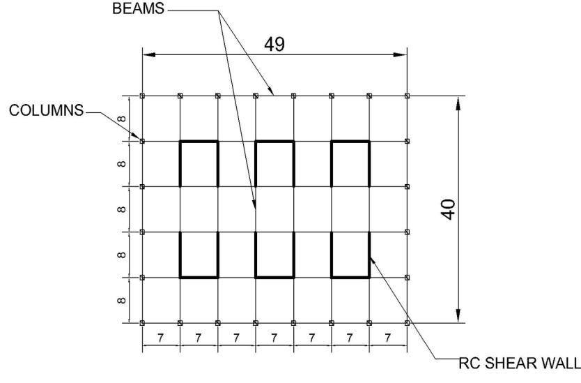
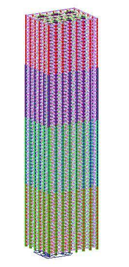
The structure's plan and elevation are shown in Figure 1.
Figure 1: Elevation and plan of the case study
III. RESULTS AND DISCUSSION
The results of the study on the dominant action of wind and earthquake, along with the ductility required for the structure, percentage of reinforcement saved, and weight of steel saved, are discussed further below.
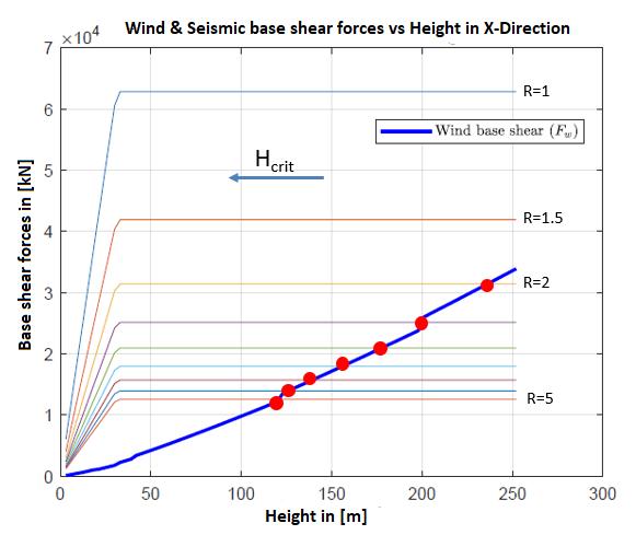
Keeping the base dimensions and basic wind speed constant, the seismic induced base shear and critical height decrease with each increment of the response reduction factor in both the X and Y-direction as shown in the figure 2
Figure 2: Wind & Seismic base shear forces vs Height in X-Direction
Page | 23 Research Publish Journals
International Journal of Civil and Structural Engineering Research ISSN 2348-7607 (Online) Vol. 9, Issue 1, pp: (21-29), Month: April 2021 - September 2021, Available at: www.researchpublish.com
Figure 3: Wind & Seismic base shear forces vs Height in X-Direction
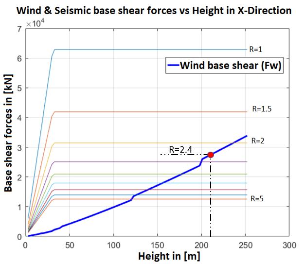
The maximum response reduction factor or ductility value attained corresponding to 210 m height is 2.40 in the Xdirection and 1.72 in the Y-direction, as shown in the figure 4 & 5. Wind is the dominant action above the point represented in graphs below, while seismic is the dominant action below that point.
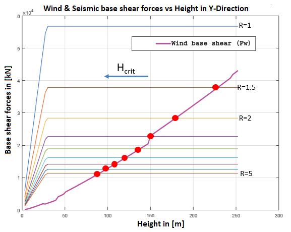
Figure 4: Intersection of Wind & Seismic base shear forces vs Height in X-Direction
Page | 24 Research Publish Journals
International Journal of Civil and Structural Engineering Research ISSN 2348-7607 (Online) Vol. 9, Issue 1, pp: (21-29), Month: April 2021 - September 2021, Available at: www.researchpublish.com
Figure 5: Intersection of Wind & Seismic base shear forces vs Height in Y-Direction
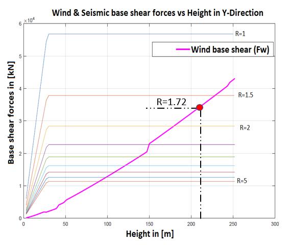
The Response Spectrum Analysis results are now detailed and commented. The values of base shear from wind and seismic actions, as well as the related ductility needed for the structure, are presented in the table 1. The structure's ductility is 2.38 and 1.72 in the X and Y directions, respectively.
Table 1: Ductility results from the Modal analysis X Y
Wind (kN) 27262.03 34113.07 Seismic (kN) 64915.61 58658.58 R’ 2.38 1.72
The ductility needed for the structure based on the Preliminary and the Response Spectrum Analyses are almost identical The maximum of the two ductility values from both the X and Y-directions has been considered, which is R'=2.4. As a result, R'=2.4 is chosen as the ductility demand for the structure and it is designed accordingly.
The potential regions for plastic hinge formulation should have significant rotational capabilities to provide the required overall ductility of the structure, which is done by providing adequate curvature ductility in all critical regions of primary seismic elements (beams, columns, and shear walls) Since there are no specifications in Indian standards, for finding the local ductility requirements for R=5 and R=2.4 and related design specifications are tuned according to EN 1998-1 (i.e., DCM). Complying to IS and European standards, For R=5, it was determined that the transverse reinforcement required is greater according to IS, implying that the Eurocode provides the most economical design.
In the beams, the volume of stirrups according to Eurocode is = 0.8*volume of stirrups (according to IS).
In the columns, the volume of stirrups according to IS are equivalent to Eurocode.
In the walls, the volume of stirrups according to Eurocode is = 0.6*volume of stirrups (according to IS).
Comparing the IS and EN standards, the normalization constant has been derived. Through normalization constant the adoptability of EN formula to comply with R = 2.4 is feasible.
According to EN 1998-1 clause 5.4.3.2.2, a value of local curvature ductility factor �� should be provided in the critical zone of the primary seismic elements (beams, columns, and shear walls) in accordance with paragraph 5.2.3.4 (3).
Page | 25 Research Publish Journals
International Journal of Civil and Structural Engineering Research ISSN 2348-7607 (Online) Vol. 9, Issue 1, pp: (21-29), Month: April 2021 - September 2021, Available at: www.researchpublish.com
Local ductility is considered satisfied in beams according to clause 5.4.3.1.2 (3) if the compression zone reinforcement is not less than half of the tension zone reinforcement, in addition to any compression reinforcement required for the ULS verification of the beam in the seismic design condition and the reinforcement ratio in tension does not exceed the maximum.
In the columns the local ductility deemed to be satisfied according to the clause 5.4.3.2.2 (8) if ��
Eq. (2)
Local ductility is assumed to be satisfied in the shear walls if clause 5.4.3.4.2 (4) is met. ��
Eq. (3)
Where, is the mechanical volumetric ratio of confining hoops within the critical regions are found according to R=5 and R’=2.4 according to IS and EN, respectively. The other terms in Eq. (3) are defined in EN 1998-1, clause 5.4.3.2.2 (8).
IS 16700:2017 also allows for the use of performance based design in buildings that are not covered by the standard. Likewise, clause C1.1.1 of the Proposed Draft Provisions and Commentary on Ductile Detailing of RC Structures Subjected to Seismic Forces [20] shows some flexibility that is, desirable to have the option for zone III to provide lower level of ductility. With all the above mentioned adaptability, we can include EN requirements into our study.
The local ductile detailing and dimensioning regulations are based on EN 1998-1 Medium class ductility for R'=2.4, whereas the detailing rules for R=5 are based on Indian standards are validated for the structure. Further calculations were performed in Excel for both R'=2.4 and R=5, and the results were compared.
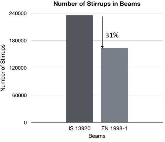
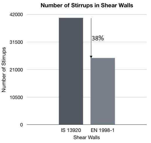
The amount of reinforcement saved in terms of percentage and weight has been determined for beams, columns, and shear walls for both R=5 and R'=2.4 and compared as shown in the figure 6,7 & 8.
As compared to R =5, the observed results indicate that there is a reduction of approximately 31 percent of transverse steel in the beam and a reduction of 20 percent in the column. In the case of shear walls, there is a considerable reduction in the transverse steel percentage as compared to beams and columns, which is 38 percent.
Page | 26 Research Publish Journals
Figure 6: Number of stirrups obtained in beams according to IS 13920 and EN 1998-1
International Journal of Civil and Structural Engineering Research ISSN 2348-7607 (Online) Vol. 9, Issue 1, pp: (21-29), Month: April 2021 - September 2021, Available at: www.researchpublish.com
Figure 7: Number of stirrups obtained in columns according to IS 13920 and EN 1998-1
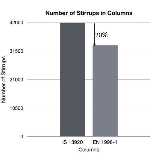
Figure 8: Number of stirrups obtained in shear walls according to IS 13920 and EN 1998-1
The table 2 shows the weight of the reinforcement that may be saved in beams, columns, and shear walls for the structure in consideration.
Table 2: Weight of the reinforcement saved in beams, columns, and shear walls
Elements Weight of the Reinforcement (Kg)
Beams 78102 Columns 22072 Shear Walls 155375 Total 255549
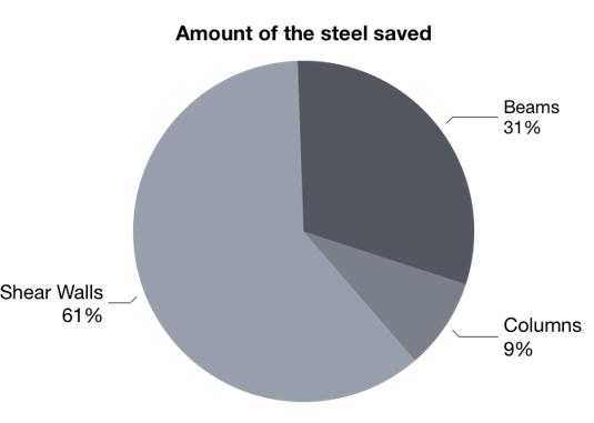
The shear walls saved the highest reinforcement (61%) in the overall percentage of reinforcement saved, followed by beams and columns (31% and 9%, respectively).
Page | 27 Research Publish Journals
International Journal of Civil and Structural Engineering Research ISSN 2348-7607 (Online) Vol. 9, Issue 1, pp: (21-29), Month: April 2021 - September 2021, Available at: www.researchpublish.com
Figure 9: Overall reinforcement percentage saved for beams, columns, and shear walls
IV. CONCLUSION
When the actual ductility demand required by a structure to be governed by the seismic response (e.g., R’= 2.4) is less than the ductility demand specified in the code (e.g., R = 5), the adoption of the prescriptive detailing provided for moderate to high intensity seismic zones is lacking of a rationale behind and uneconomical. The observed results indicate that by providing ductile reinforcement according to the current ductility demand, the amount of reinforcement decreases of approximately 30% of transverse steel in the beam and a decrease 20% in the column. When compared to beams and columns, shear walls have a higher percentage of steel reduction, which is 38%. The total weight of steel that can be saved for the analysed structure is around 280 tons. Along with the cost and material, considering R’= 2.4 will save a lot of time because it will take longer to assemble the additional steel according to Indian requirements R = 5. Construction is also more rapid. For tall structures, this method provides the most rational and economical solution.
V. FUTURE STUDY
This work would serve as basis for the economical of tall structures in high wind and low to moderate seismic areas. This is followed by nonlinear analysis, such as nonlinear static and nonlinear dynamic analysis, to determine the structural response beyond the elastic range. Furthermore, the deterioration of strength and stiffness related with inelastic material behaviour and large displacements can be determined. This can also be applied to the design of new structures that do not meet current building code requirements.
REFERENCES
[1] Aly, A. M., & Abburu, S. (2015). On the design of high-rise buildings for multihazard: fundamental differences between wind and earthquake demand. Shock and Vibration, 2015.
[2] Zheng, C., & Lu, M. (2016). Optimized reinforcement detailing design for sustainable construction: Slab case study. Procedia Engineering, 145, 1478-1485.
[3] Rana, E. N., & Rana, S. (2014). Structural forms systems for tall building structures. SSRG International Journal of Civil Engineering, 1(4), 33-35.
[4] Moehle, J. P. (2008, October). Performance-based seismic design of tall buildings in the US. In 14th World Conference on Earthquake Engineering
[5] Miranda, E., & Bertero, V. V. (1994). Evaluation of strength reduction factors for earthquake-resistant design. Earthquake spectra, 10(2), 357-379.
[6] Malekpour, S., & Dashti, F. (2013). Application of the direct displacement based design methodology for different types of RC structural systems. International Journal of Concrete Structures and Materials, 7(2), 135-153.
[7] Li, Y., & Ellingwood, B. R. (2009). Framework for multihazard risk assessment and mitigation for wood-frame residential construction. Journal of structural engineering, 135(2), 159-168.
Page | 28 Research Publish Journals
International Journal of Civil and Structural Engineering Research ISSN 2348-7607 (Online) Vol. 9, Issue 1, pp: (21-29), Month: April 2021 - September 2021, Available at: www.researchpublish.com
[8] Lestuzzi, P., & Badoux, M. (2003, May). An experimental confirmation of the equal displacement rule for RC structural walls. In Proceedings of the fib-Symposium
[9] Laterza, M., D‟Amato, M., P Thanthirige, L., Braga, F., & Gigliotti, R. (2014). Comparisons of codal detailing rules for curvature ductility and numerical investigations. The Open Construction and Building Technology Journal, 8(1).
[10] Gunel, M. H., & Ilgin, H. E. (2007). A proposal for the classification of structural systems of tall buildings. Building and environment, 42(7), 2667-2675.
[11] Calvi, G. M., Priestley, M. J. N., & Kowalsky, M. J. (2007). Displacement based seismic design of structures. In New Zealand Conference on Earthquake Engineering (p. 740). IUSS press.
[12] Duthinh, D., & Simiu, E. (2010). Safety of structures in strong winds and earthquakes: multihazard considerations. Journal of structural engineering, 136(3), 330-333.
[13] Bakens, W., Foliente, G., & Jasuja, M. (2005). Engaging stakeholders in performance-based building: lessons from the Performance-Based Building (PeBBu) Network. Building Research & Information, 33(2), 149-158.
[14] Bruneau, M., Barbato, M., Padgett, J. E., Zaghi, A. E., Mitrani-Reiser, J., & Li, Y. (2017). State of the art of multihazard design. Journal of Structural Engineering, 143(10), 03117002.
[15] Ali, M. M., & Moon, K. S. (2018). Advances in structural systems for tall buildings: emerging developments for contemporary urban giants. Buildings, 8(8), 104.
[16] Chen, E. (2012). Multi-hazard design of mid-to high-rise structures.
[17] ANESI, R. (2019). A synthetic approach to tall building design with respect to horizontal effects.
[18] Chen, E. (2012). Multi-hazard design of mid-to high-rise structures.
[19] Newmark, N. M., & Hall, W. J. (1973, February). Procedures and criteria for earthquake-resistant design. In Selected Papers By Nathan M. Newmark: Civil Engineering Classics (pp. 829-872). ASCE. [6].
[20] Jain, S. K., & Murty, C. V. R. (2005). Proposed draft provisions and commentary on ductile detailing of RC structures subjected to seismic forces. IITK/GSDMA, EQ11-v4 & EQ16-v3 IIT, Kanpur.
[21] Kim, S. (2019). Seismic performance evaluation of high-rise steel buildings dependent on wind exposures. Advances in Mechanical Engineering, 11(3), 1687814019835111.
[22] Thilakarathna, S. N., Anwar, N., Norachan, P., & Naja, F. A. (2018). The effect of wind loads on the seismic performance of tall buildings. Athens Journal of Τechnology & Engineering, 5(3), 251-276.
[23] Potra, F. A., & Simiu, E. (2009). Semi-infinite programming in multi-hazard structural design. Computer Aided Optimum Design in Engineering XI, 106, 13.
Page | 29 Research
Publish Journals