
12 minute read
Design Comment


DESIGN
COMMENT
Michael Paloian, Integrated Design Systems, Inc.
Design Details
How many times have you seen a great concept rendering for a new product and experienced major disappointment when you saw the first production assembly based on that inspirational design? It happens frequently so you shouldn’t feel alone. There is an adage; “The devil’s in the details” which becomes much more significant as one gains experience designing and developing products. When I was much younger, I didn’t pay much attention to this advice and learned that design details is the magic which distinguishes great product design from mediocrity. All visually appealing designs share a few common traits. The number one most significant trait is simplicity. Industrial designers always try to unify many unrelated components, features, and parts into a single overall ...DISTINQUISHES GREAT PRODUCT dominant form which expresses the product’s function. This can be a very DESIGN FROM MEDIOCRITY. challenging task, especially when a product is comprised of many parts and distinctly different components. The challenge lies in the creative expression of the product based near perfect alignment to one another. Parts can’t be molded on an overall shape which defines its function based on an with poor witness lines, rough textures, or pins holes in the appearance which brands the company’s identity. surface. These are examples of design details. Part quality is
After an overall simple form has been created, it will remain dependent on the designer as well as the mold maker, molder somewhat boring because of its lack of details. A few great and resin supplier. All these stakeholders must work together as examples are flat screen TVs, cell phones, and computers. All a unified team with a common vision. The designer is a critical these products are essentially flat rectangular forms. They would participant in this process. He or she must motivate the team to all be indistinguishable from one another without their specific attain the highest levels of design excellence without impacting details. The same holds true for the same product manufactured production efficiency or increasing part cost. This requires a keen by different companies. Differentiating one flat screen TV from understanding of the process, tooling methods, and materials, another is much more difficult than distinguishing one X-ray which must be accommodated in all the design details. Examples machine from another because the state of the art and number might include specifying machined tools with an etched surface of parts. As products become simpler, your eye focuses on texture or the specific split line for parting the mold. Another smaller details, which would typically go unnoticed in a more might include the details for a joint between two parts based on complicated assembly. reasonable clearances and required radii along edges.
Rotational molding is expanding into markets where Although this brief editorial only scratched the surface of appearance and quality are critical to a product’s market design details, I hope it made an impact on you. The next time appeal. Since many of these products are expensive, consumers you develop a product, you’ll hopefully realize all the time, expect their purchase to be of high quality, highly reliable, and cost and energy invested in design goes into part detailing. exceptional performance. The covers and overall structure The concept is only 15-20% of the overall product development must be molded with excellent surface finish, precision fits, and or success in the market.
The Use of Virtual Reality in the Development of a New Rotational Moulding Factory
Karem Akoul, Peter Ross, Brian Allen and David Seall CP Cases, London; Mark Kearns and Dr. Peter Martin, Queen’s University, Belfast
CP Cases, based in London, England is a vibrant, fast growing company that designs and manufactures high-performance protective cases for the storage and transport of high-value equipment for the media, entertainment and commercial industry. The company has over 45 years of experience in the design and production of cases and containers in plastics, welded aluminium, specialist rugged textiles and foam engineering. For the past 18 months CP Cases has been collaborating with the Polymer Processing Research Centre, School of Mechanical & Aerospace Engineering, Queen’s University, Belfast (QUB) as part of a 30-month UK Government (Innovate UK) sponsored Knowledge Transfer Partnership project, known as KTP. The project is specifically aimed at introducing and embedding the rotational moulding process into CP Cases production capabilities. The rapidly changing market demand has driven the project team to consider data acquisition in the early stages of planning.
This article describes aspects of the project where the use of Virtual Reality (VR) techniques has been used to benefit and optimise the new rotomoulding factory set up, layout and design.
Industry 4.0 and Virtual Reality
Data acquisition, ubiquitous connectivity and real-time communication are changing how manufacturing companies function and operate. Is it a revolution or just the common-sense strategic deployment of new technology? There is now a growing understanding that elements of what we call “Industry 4.0” can be deployed at a relatively low cost and deliver immediate benefits. Industry 4.0 technologies and their increased use of digital and analytics are already improving manufacturing productivity, efficiency, and effectiveness. Digital advances and better human-machine interfaces are enhancing problem solving, operator training, and overall production performance. Lower automation costs are fundamentally changing discussions about when and how to use automation in manufacturing. There is growing consensus that the core concept, which hinges around the deployment of automation technologies and smart use of data, is critical to the future of manufacturing operations, large and small. Industrial production was transformed by steam power in the nineteenth century, electricity in the early twentieth century, and automation in the 1970s. Today, manufacturing is experiencing a fourth wave of technological advancement; the rise of new digital industrial technologies that are collectively known as Industry 4.0.
Factory layout planning is a long-standing area in production engineering that sees great potentials of VR integration. It is getting wider attention in both research and practice as the virtual environment allows designers and planners to test out “what if” scenarios with relative ease.
Benefits of Factory Layout Planning
One of the main benefits of building a 3D Model of a proposed new factory and using VR to visualize it is overcoming the distances between the project’s stakeholders. The richness and flexibility provided by a virtual model allows a ‘common view’ and better understanding for all of the planning team which improves and accelerates the decision-making processes. The decision making is also promoted by the ease of getting opinions and ideas from all levels of engineering and management by the simple platform that the VR layout provides.
Another main benefit of Virtual Layout Planning is that it increases the amount of knowledge and understanding for cross functional teams at early stages of the project. 2D layouts could
(a)

(b)

Figure 1: Cost of Change diagram with Classic (a) and Automated (b) Design processes
sometimes be sufficient to evaluate some quantitative measures, such as footprint, travel distance and product flow. However, they are often only understood by ‘experts’. 3D representation on the other hand and virtual visualisation helped bridge the gap between areas of expertise. In addition to the quantitative measures, virtual layout plan allows assessing some qualitative measures prior to execution such as factory safety, ergonomics and operator preferences.
In any design process, the designers have the largest freedom of choice at the very early stages whilst the cost of change is still negligible. However, the knowledge and experience the designer has is relatively low at this stage. Virtual planning boosts the level of knowledge at the planning stage (see Figure 1). CAD model, allows for running mini Six Sigma® and continuous improvement projects, and gives the chance to access its feasibility and efficiency prior to execution.
Virtual Reality in Rotational Moulding
The first step in planning for turning an empty building into a rotational moulding plant is determining the position of the machine. The ease of moving the machine in the virtual model is very efficient in determining the optimum position and gives the planning team a

Having a live and continuously updated realistic appreciation of the actual size of equipment. It would be very costly and physically difficult to change the position of the machine after installation which is further discussed in the next section.
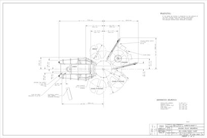
The carrousel machine being considered had limited layout drawings. Therefore, it was very necessary to create models that could be easily integrated with the factory layout and viewed with VR to get a clearer appreciation of the actual footprint and size of the machine.
Viewing the machine, positioned in the right place, together with utilities and ancillary equipment greatly assisted the 3390 planning and design teams, particularly 2560 3500
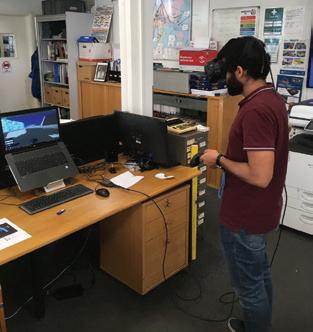
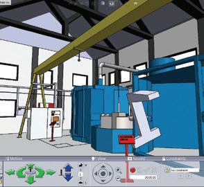
Figure 2: Demonstration of the Use of VR headset to navigate the Factory 3D Model
11000
9175
7300
6700 with spotting some problems that have 2465 3000
a high chance of occurring and avoid 3140
them at an early stage. An example here was related is the positioning of the Gas meter and making sure it is in a safe and accessible position in 4300
case of emergency. 2125
Integrating the 3D Models of the factory, machine and crane 0
was also important to verify the exact position and angle of 0 1875 3800 5800 7800 9650 11500 13325 15150 17275 19400 21175 22950 24975 27000 27734 28625 30700
the crane that makes perfectly aligning with the 2 servicing
Revision
Revision Table Description Date Approved
6942.7 4602 500 1000 8958.6
18°
72° 72°
72°
8204 72° 90°
18°
72°
Notes:
1) The precooling Station shall be Perpendicular to the roller shutter door. 2) The line connecting the centerlines of the two servicing stations shall be parrelel to the roller shutter door. 3) Both The oven and the cooler are tilted by 18 to the roller shutter door.
Project
Unit 6 Rotomoulding
Drg. No.
Machine Position
Date
24/03/2020
Drawn By
KA
Revision
A
CP Cases Ltd.
Scale Sheet No. Worton Hall Industrial Estate, Worton Road, 1:100 If in doubt ASK 1 of 1 Tel: Isleworth, Middlesex, TW7 6ER, UK. +44 (0) 20 8568 1881 Fax: +44 (0) 20 8568 1141 Dimensions In Millimeters. Email: info@cpcases.com Website: www.cpcases.comDo Not Scale. Third Angle Projection. Copyright CP Cases Ltd. This drawing is the property of CP Cases Ltd & the information on it is confidential. It is not to be used for any other purpose without the prior written consent of CP Cases Ltd.
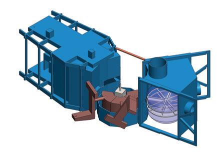
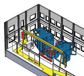
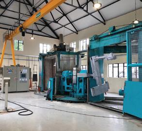
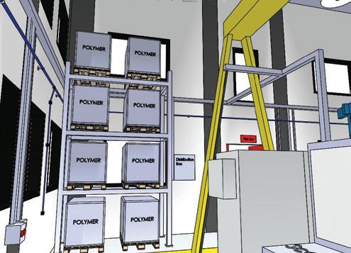
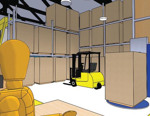
Figure 4: Virtual Factory Layout of CP Cases Rotomoulding Facility
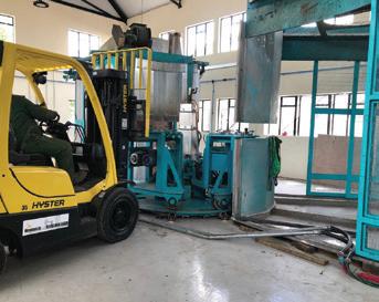
stations. Other issues such as the obstruction of the pathway of the forklift and inaccessibility of the critical positions of the machine during maintenance, where also considered, evaluated and avoided at this early stage.
The screenshots in Figure 4 show different parts of the factory where the use of VR helped take a quick and firm decision from all the stakeholders.
Financial Analysis
Despite all the aforementioned benefits of using VR in factory layout planning, some still doubt the return on investment of using such a system, because the capital cost and modelling time required. The main reason for these doubts is that the estimated cost saving of making the change using VR during planning is always intangible. However, if we were to evaluate the feasibility of the system, we can evaluate repositioning of the machine as a case study.
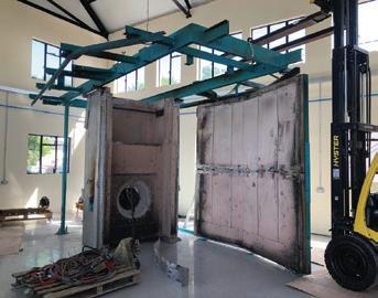
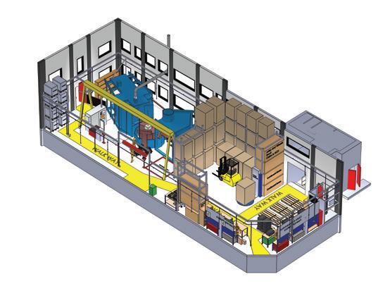
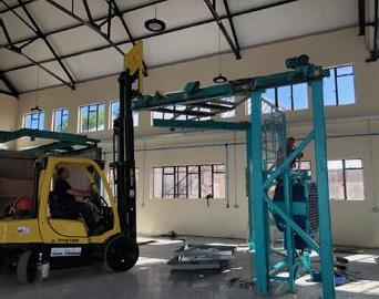
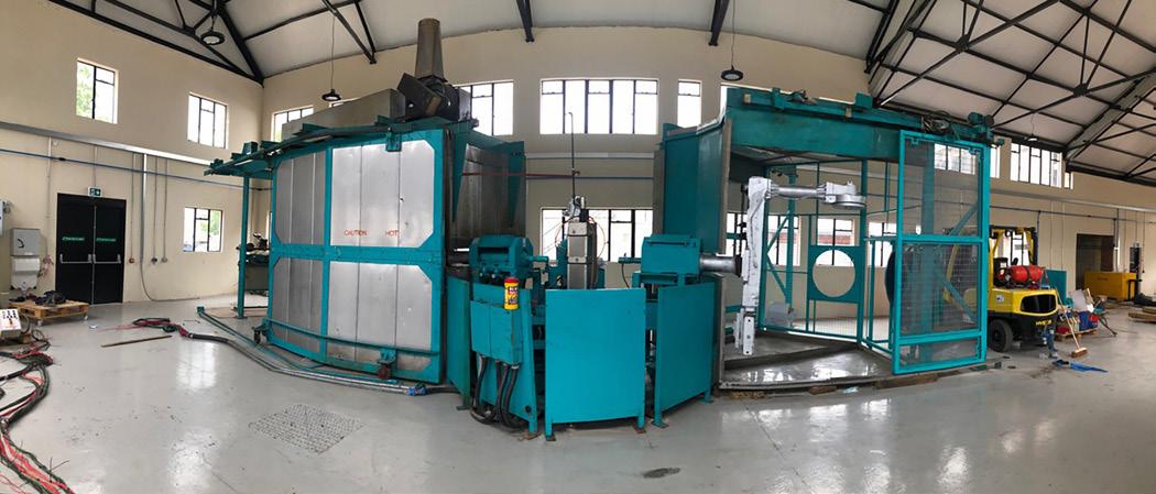
Figure 6: Safe operating height virtual assessment
Firstly, the virtual planning approach used requires a desktop and a SolidWorks license, both already present and available in the design department. In addition, an HTC Vive VR headset was purchased for this purpose at $650. This project required 4 months for planning, which included 4 weeks of modelling at a cost of $5000. Therefore, the total cost of the VR analysis was approximately $5650 (not including the computer hardware and CAD software). For every design change such as repositioning the machine, the team spent about half a day to discuss, model and evaluate the change. This resulted in an additional cost per iteration of approximately $300.
If the repositioning was carried out after the machine installation and during the testing, that would require at least 1 working week of physical reconstruction, with a cost of at least $12,000, which is 40 times the cost of change during the early stages.
If the repositioning was carried out after factory commissioning and start of production, that would add the cost of stopping production for 1 week, in addition to the cost of moving the machine, which would yield a total cost of $20,000, which is 65 times the cost of the virtual change.
So, generally speaking, the financial gain of using VR in virtual layout planning is dependent on the complexity of the project, the cost of the physical change and the expertise and knowledge of the planning team.
Future Work
When the project is successfully executed and the production starts at the new factory, the use of CAD and VR will still continue to support and optimize production; those activities would include: • Design of cooling jigs and frames and testing the operators’ ergonomics and preferences before manufacturing. • The mass properties of CAD software could be used to design self-balancing arms without the continuous need of manual
Figure 7: Raw material storage virtual assessment
arm balancing.
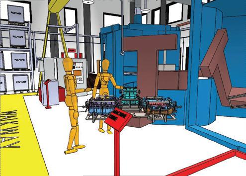
Figure 8: Finishing and Assembly line virtual assessment

Figure 9: Finished product storage virtual assessment
FEA analysis is currently and will be used to check the frames and arm strength and make sure they will support the tools. The design and development team can assist the production team with some CFD analysis to optimize the heating and cooling processes.


