2020-2023
Portfolio. Selected Work I Rucha A Valimbe

2020-2023
Project Location: Eastern Gateway, Manchester
Client: Manchester City Council
Project brief: Propose low- carbon to zero carbon solutions for the regeneration of Eastern Gateway, as a consultant for Manchester City Council.
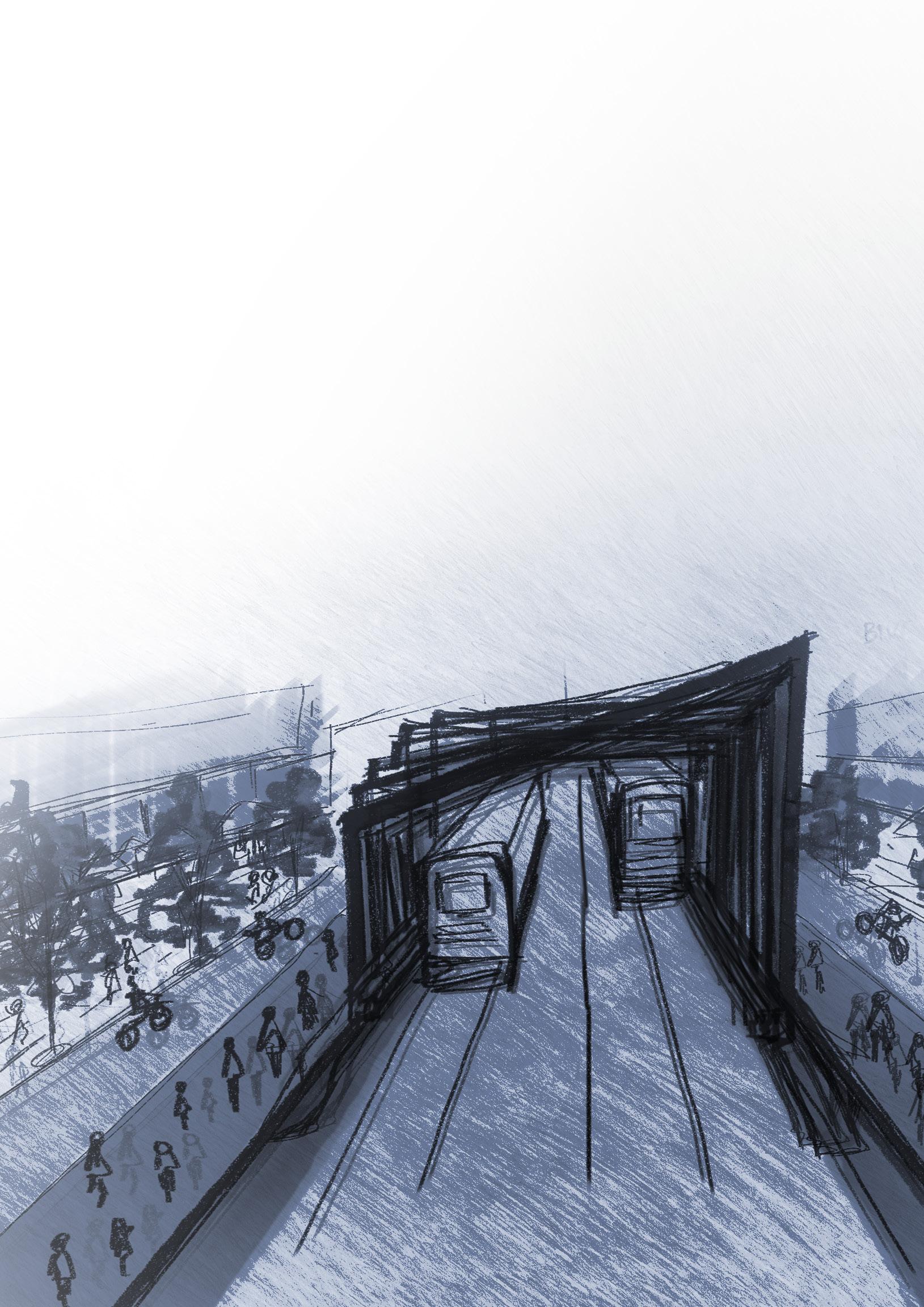
Our Vision: Our site is based in East Manchester, which has, in the recent years seen an increase in the use of private cars as primary modes of transport to pursue daily activities. This has caused exponential environmental harm. As a response, we have applied urban design principles such as Transit oriented development and 15-minute city, to achieve generative urban patterns, through a computational design process.
Project Software:


Our Computational Tool Generating urban patterns with an aim of lowering travel times to local amenities by controlling the street network and plot sizes, in order to achieve a zerocarbon city.


I along with my project partner, created a computational tool using Rhino and Grasshopper. To generate the Street network we utilised the method of Parcellation. The site was divided into blocks of 400x400m inspired by the concept of Superblocks.
For allocating land uses, we created a tool to place the transit oriented clusters over the existing tram lines on the site. We then scripted an iterative loop to allocate specific land usesCommercial, Retail, Sports/ Recreation and Education within the mixed use zones. Following this step, we created typologies to be placed on the generated plots.


Once we generated twelve distinct iterations with the help of our computational tool, I created a User Interaction Tool using Unity.
1. Street Network Generation
2. Land Use Allocation


The road network was designed based on the concept of superblocks. The urban plan was divided into regions, which was then parcellated into 400 x 400 m blocks, and then further divided into smaller plots. This image zooms into a 400x400m block.

1. Roads that lie surrounding the blocks are designed to accommodate residents’ vehicles, urban services and emergency vehicles.
2. Roads lying within the blocks would be accessed by pedestrians and bicycles.
3. Tram line running centrally located within the block. the road is designed to include tram tracks, bicycle paths and pedestrian walkways.
WALKABILITY SCORE
3.63

CO2 EMISSIONS DUE TO TRAVEL (gCO2/yr)
3,751,400
Embodied CO2 emissions: Residential
1. Buildings: 28,994,000 kgCO2
2. Detached houses: 1,422,500,000 kgCO2
(For all buildings within the sector)
Embodied CO2 emissions: Commercial
17,618,000,000 kgCO2
(For all buildings within the sector)
1. 1. 2.
Embodied CO2 emissions: Retail
600,170,000 kgCO2
(For all buildings within the sector)
Embodied CO2 emissions: Sports, Rec
835,250,000 kgCO2
(For all buildings within the sector)
Embodied CO2 emissions: Education
346,400,000 kgCO2
(For all buildings within the sector)

Project Location:
Manchester

Client: MMU Estates
Project brief: Adaptive Re-Use of Righton building (Grade II Listed*) to create makerspaces and learning commons.
Our Vision:
A scheme incorporating makerspaces and learning commons to initiate collaboration between the existing fashion department within Righton building and the MMU Digital Arts department. Our aim is to equip students for the ongoing digital transformation of the fashion industry.
Project Software:


*Building must be more than 30 years old before its listed as Grade II. Buildings are important due to technological innovation, or illustrating particular aspects of social or economic history, have external visual quality. Listed elements in Righton building that we retained:
 1. Primary structure, decorated columns and beams
2. Art Nouveau character of the interiors and exterior facade
3. Raised lettering on the frontal arched parapet “A.D. RIGHTON 1905”.
1. Primary structure, decorated columns and beams
2. Art Nouveau character of the interiors and exterior facade
3. Raised lettering on the frontal arched parapet “A.D. RIGHTON 1905”.
Massing Diagram:
I created a massing model on Rhinoceros 3D & Revit, and edited the same with Adobe Suite to highlight the programme distribution in our building.


Construction Sequence:
I created diagrams by exporting layers from the 3D model created. These were then edited in Photoshop to visualise the construction sequence of the project.
A. Demolish existing cores, service stairs, internal walls
E. GFRC structural floor slab built over the new cores introduced.
B. Existing listed structure and facade elements to be re-used
F. Glu-laminated timber structural frames attached to the floor slab.
C. Laying out new pile foundations
G. Envelope layers installed over the glulam structural frames attached to the concrete floor slab.
D. Building new cores to support the intervention.
H. Interior walls and finishings to be installed.

2mm anodized sheet steel gutter
Detail Drawings: Based on research and discussions with Studio tutors, I created drawings to highlight the construction details for the project. These were done using AutoCAD.
Structural strategy:
The new structure connects to the existing Righton building through two cores, designed to be centrally located within the building. I created a model in Rhinoceros 3D to visualise our new structure.
I created the diagram shown on the far right to highlight our envelope strategy. This was created by developing an exploded model in Rhinoceros 3D.
3mm Metal flashing
LED Strip lighting
Steel angle
DETAIL 01: Roof and exterior wall connection
Drawn at Scale 1:5
Secondary structure 150mm
Ceiling Vents
Aluminium Frame
Triple Glazing
Suspended ceiling ties
• Thermowood timber cladding 20mm
Timber battens 100x50mm
• Rigid Insulation 120mm
• Wooden sheathing
Glulam Structural frame 1200x240mm
• CLT Structural frame
• Wooden Sheathing 20mm
• Rigid Insulation 120mm
• Acoustic Insulation 25mm
• 50mm air barrier within 170x50mm vertical timber battens
Horizontal timber battens 50x50mm
• Thermowood timber cladding 20mm
Ceiling LED Lights
Thermowood cladding 20mm
• Horizontal timber battens 130x50mm
• Vertical timber battens 100x50mm
Acoustic insulation 25mm
• Rigid insulation 95mm
• GFRC Structural floor slab
• Floor screed 75mm
• Carpet 10mm (events space)
Plasterboard Ceiling 20mm
DETAIL 02: Floor and exterior wall connection
Drawn at Scale 1:5
Flashing lapped over waterproof membrane
Triple Glazing
• 300mm wide gravel bed
• 3mm retention trim
• Green roof system soil 100mm
Damp proof membrane
• Rigid insulation 100mm
• Existing floor slab (concrete) 180mm
• Existing Beam
50mm adjustable height pavers
Water reservoir 50mm
DETAIL 03: Balcony & exterior wall connection
Drawn at Scale 1:5
Timber Roof Cladding
Vertical, horizontal timber battens
Timber Board
Rigid Insulation
Glu laminated timber

Metal flashing
CLT structural panel
Wood sheathing board
Insulation + air gap within timber battens


Horizontal timber battens
Timber cladding
Glazing
Thermowood facade
Glu-laminated timber structural frames GFRC Floor Slab
Carpet floor finish for events space
Thermowood

Concrete floor slab

Concrete pile foundation
Pile cap: 1000 x 800 mm
Diameter: 800mm
Structural Core
cladding (envelope) Adding new structure to existing Righton buildingTravel distance: In compliance with Approved document B, maximum travel distance (where travel is possible in more than one direction) in the events space is considered to be 32m. The maximum travel distance in multiple directions in other assembly and places of recreation is considered to be 45m in our design, in compliance with Part B.
Escape routes and exits: According to approved document B, the minimum width of escape routes required to accommodate 220 people (approx. no. of people on events floor) is 1050mm. The building is designed to incorporate five exits on the ground floor, two of which are 1050mm in width and fire rated.
N
Ground floor Plan

Lifts for vertical circulation
Toilets
PART M
Lift cars exceeding as per 1400mm), of people providing Toilets are access with M as shown.
M - Access to and Use of Buildings
are designed to be 1760 x 2100mm, exceeding the minimum required dimensions the approved document M (1100 x 1400mm), to accommodate higher number people during fashion events, while also providing wheelchair accessibility.


are designed to incorporate disabled with compliance to approved document shown.

SSH Design, Dubai
Location: Sharjah, UAE
Client:
Eagle Hills Properties, Shurooq
Project Scope:
• Concept Enhancement
• Detailed Masterplan design: Land Use, Plot guidelines, Phasing strategy, Building and site sections/ elevations
Programme:
The masterplan consists of 28 plots with 3 star and 4 star hotel buildings, commercial and residential buildings, an events space facing the waterfront and a souk. The masterplan is designed to create zones such as the glade, civic quarter, the village, urban quarter and waterfront, each one with its own distinct feature/ programme.

Project Software:

AutoCAD SketchUp Illustrator InDesign


I was involved in creating a programme distribution plan as shown on the right.
3D Model:
I created a SketchUp massing model that helped the team to visualise the masterplan and define the building heights, zones and high moments.
Section Drawings:
I created section drawings to showcase streetscape within the masterplan. These drawings were aligned with the drawings received from the transportation consultants assigned to the project.
Drawing is the intellectual property/copyright of SSH Design, Dubai. Work prepared during internship and included to demonstrate capability.
AutoCAD SketchUp Illustrator

Under the guidance of a Lead Architect at the firm, I created document control sheets to include the plot regulations and guidelines for each plot within the masterplan.
As part of the same, I was responsible for exporting views from the SketchUp model to showcase the building massing, envelope, open spaces, building setback within the plot boundary.

I also created plans and sections as shown on the right, to showcase the building heights, setback, active edges, building and landscape extents, parkings and pedestrian access within the plot boundary.
Drawing


SSH Design, Dubai
As part of this project, I was responsible for creating concept diagrams for client presentations. The diagrams below show our promenade/ podium strategy. I created these using Illustrator.


Full Podium
Expensive to build, disconnects levels
Project Location: Ras Al Khaimah, UAE
Project Stage: Pre-concept design

Programme: The project execution will be split into 3 phases:
Phase 1: 4* Hotel, F&B Retail Complex, Beach Villas, detached Villas, Entertainment Zone, Beach Facilities and Landscape.
Phase 2: Branded Serviced Apartments, semi detached Villas and Residential Buildings.
Phase 3: Branded Serviced Apartments, semi detached Villas and Residential Buildings.
Project Software:
Half Podium
Expensive to build, disconnects levels
Minimum Built Road Level 446 car park spaces at road level/ 792 car park spaces on beach level
Outdoor 26,855m2 = 34.5%
Podium 16,187m2 = 20.8% Site coverage = 55.3%
Podium Parking = 25,237m2 = 32.4% Building = 10,740m2 = 13.8%
InDesign Illustrator Model making
I created a massing model of the masterplan that helped the design team to develop our concept. I was responsible for updating the model as and when changes were introduced in the design.
SSH Design, Dubai
Project Location: Dubai, UAE
Client: Emaar Properties
Project Stage: Phase 1 & 2: Construction
Stage
Phase 3: Tender Stage Phase 4 & 5: Not started
Programme:
Forty eight residential buildings to be built in five phases and covering a total GFA of approximately 592,000 sqm. The buildings are distributed in clusters. Every cluster comprises of around 300 apartments each with one, two, three and four bedroom apartment types.
Project Software:

As part of the project I was assigned to create two material sample boards to be sent to the building under construction. To create these I was required to meet with material suppliers and collect samples, referring to a material specifications sheet developed by the team. The material boards were successfully delivered to the site.

 Penthouse Elegant
Apartments Modern Option A
Revit AutoCAD Microsoft Office
Penthouse Elegant
Apartments Modern Option A
Revit AutoCAD Microsoft Office


I worked on client comments for one, two and three bedroom apartments with guidance of Architects and Senior Architects at the firm. This involved arranging floor tiling layouts, furniture, sizes of fixtures and drain positions according to client requirements and building regulations.
- I also created two internal elevations each for the two types of two bedroom apartments of the scheme.
1- Do not scale from this drawing. Dimensions are in millimeter unless otherwise stated.
2- This drawing must be read in conjunction with all other relevant drawings.
3- Contractor must report any discrepancies prior to execution of any works.
4- All dimensions must be verified on site prior to order or manufacture of materials or production of site drawings.
5- All shop drawings to be submitted to the architect / interior designer for comment prior to fabrication.
6- Samples must be submitted to interior designer for comment prior to manufacture.
7- Drawings to be read in conjunction with FF&E , Finishes & Sanitary schedules.
8- Refer to details drawings for further floor, wall , ceiling and door information.
9- Samples of all visible M&E fixtures to be submitted to interior designer for comments.
10- Refer to lighting information by services engineer and lighting consultant for setting out and specification of non decorative lighting . All samples to be submitted to interior designer for comment.
11- Operator and MEP consultant to determine specification of all audiovisual fittings within the ceiling. Location to be determined by operator , AV, MEP.
12- All structural requirements relating to interior design elements are to be confirmed by the structural engineer.
13- Refer to acoustic consultant documentation for further information with regards to acoustics.
14- For wall types,Facade windows and doors refer to architectural drawings package.
15- For balcony Floor drain refer to ID 200 series.
designer for comment prior to
6- Samples must be submitted to interior designer for comment prior to manufacture.
7- Drawings to be read in conjunction with FF&E , Finishes & Sanitary schedules.
8- Refer to details drawings for further floor, wall , ceiling and door information.
9- Samples of all visible M&E fixtures to be submitted to interior designer for comments.
10- Refer to lighting information by services engineer and lighting consultant for setting out and specification of non decorative lighting . All samples to be submitted to interior designer for comment.
11- Operator and MEP consultant to determine specification of all audiovisual fittings within the ceiling. Location to be determined by operator , AV, MEP.
12- All structural requirements relating to interior design elements are to be confirmed by the structural engineer.
13- Refer to acoustic consultant documentation for further information with regards to acoustics.
14- For wall types,Facade windows and doors refer to architectural drawings package.
15- For balcony Floor drain refer to ID 200 series.
Drawing is the intellectual property/copyright of SSH Design, Dubai. Work prepared during internship and included to demonstrate capability.
Revit