20 minute read
A practical design approach for an improved resin-anchored tendon

from Saimm 202001 jan
by SAIMM

B.R. Crompton 1 and J. Sheppard 1
Advertisement
Affiliation: 1 New Concept Mining, South Africa.
Correspondence to: B.R. Crompton
Email: brendanc@newconceptmining. com
Dates: Received: 25 Jul. 2019 Revised: 14 Aug. 2019 Accepted: 30 Aug. 2019 Published: January 2020
Synopsis The use of resin-grouted tendons is a common ground support practice in the mining industry, and various tendon designs are available. The support strength of a resin-grouted tendon is often constrained by the resin annulus between the tendon and the borehole. Effective mixing of the resin is typically achieved by ensuring the resin annulus does not exceed a specified maximum limit. Therefore, in some cases, the diameter of the tendon is dictated by the maximum allowable resin annulus and minimum diameter borehole that can be drilled and not by the support design requirements. Tendons with mastic resin capsules are prone to ‘gloving’ by the capsule packaging, thereby debonding the tendon from the borehole, and compromising the mixing of the resin surrounding the tendon. This paper documents a practical investigation into the effectiveness of typical resin tendon designs in large annulus installations, and the development of an improved tendon design for such cases.
Keywords resin, rockbolt, annulus, mixing, voids, design.
How to cite: Crompton, B.R. and Sheppard, J. A practical design approach for an improved resin-anchored tendon. The Southern African Insitute of Mining and Metallurgy
DOI ID: http://dx.doi.org/10.17159/2411- 9717/845/2020
This paper was first presented at the Deep Mining 2019 Conference, 24–25 June 2019 Misty Hills Conference Centre, Muldersdrift, Johannesburg, South Africa.
Introduction Various designs of tendons and resin compositions are available for ground support in mining operations. In order to optimize the support design for safety and value, it is important to assess the resin and tendon as a system and not as separate elements. This paper presents a practical investigation of the effectiveness of various resin-rockbolt systems and the design of a tendon to optimize the mixing of resin during installation and maximize the strength of the installed ground support system.
This research was focused on resin bolt applications in hard rock mines with airleg rock drills, where a combination of larger support hole diameter and inconsistent resin mixing adversely affects the installation quality of resin rockbolts. The occurrence of ‘gloving’ in mechanized and soft rock applications has been well documented (Campbell, Mould, and MacGregor, 2004; Craig, 2012). The findings are therefore relevant to resin bolting in general.
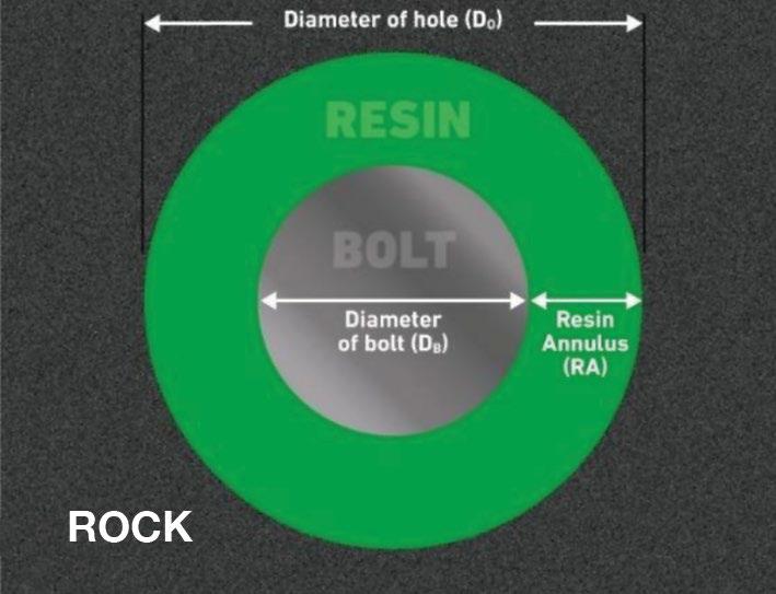
Resin annulus The thickness of the resin surrounding the installed tendon (see Figure 1) is a critical determinant of the support capacity of the rockbolt, as the mixing and resultant strength of the installed resin bolt is dependent on adherence to the resin annulus limits as specified by resin manufacturers (Ferreira, 2012).
Industry testing in soft rock applications has indicated that the optimal annulus range to maximize the bond strength of conventional ribbed bolts lies between 2.5 mm and 4.5 mm, as illustrated in Figure 2 (Canbulat et al., 2015; Mark et al., 2003). Laboratory testing using internally threaded pipes, which approximate hard rock applications, has confirmed that the optimal annulus for resin bolting is approximately 24 mm (Snyman, Ferreira, and O’Connor, 2011).
South African hard rock mines commonly use 34 mm diameter drill bits with pneumatic rock drills when drilling support holes. Measurement of 37 holes found that the drilled hole diameters varied from 32 mm to 37 mm (see Figure 3; Crompton, 2007). Although the average support hole diameter measured was 35 mm, 30% of the measurements exceeded 36 mm. Factors such as age and wear of the drill bit, adherence to discard criteria, condition of the rock drill, and the quality of the compressed air supply all impact on the hole diameter.
Given the recommended resin annulus range of 2 mm to 4 mm for resin bolting in both soft and hard rock applications, Table I indicates the mismatch between common diameters of rockbolts and the range of support hole diameters.
Figure 1—Definition of resin annulus
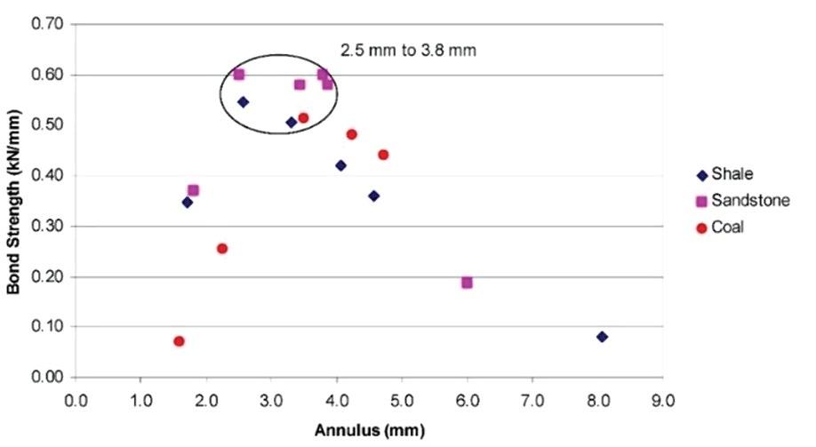
Figure 2—Effect of annulus on bond strength (Snyman, Ferreira, and O’Connor, 2011)
To alleviate the restrictions imposed by the resin annulus, a number of tendon designs are available with altered geometry in the anchoring portion of the tendon. This is typically achieved by the use of paddles or by increasing the diameter of the bolt.
Gloving Gloving occurs when the plastic cartridge of the resin capsule partially or completely encases a length of the tendon during installation. Gloving is typically accompanied by poor mixing of the resin surrounding the rockbolt. Gloving is a problem common to all resin and bolt manufacturers, and occurs in all rock types, and can happen whether the resin bolt is installed with hand-held or mechanized equipment (Campbell, Mould, and MacGregor, 2004). Despite continued research into improving the effectiveness of resin bolting systems, gloving continues to be a widespread occurrence in industry (Purcel et al., 2016). Figure 4 shows an extreme example of gloving from dynamic laboratory testing of a resin rockbolt conducted by the authors when testing a 2.4 m sample of a common paddle-type tendon with a 45° cropped tip installed in a steel pipe.
The prevalence of gloving in resin bolt installations poses a risk in terms of the immediate support capacity of the installed rockbolts as well as the long-term corrosion protection of the steel tendons.
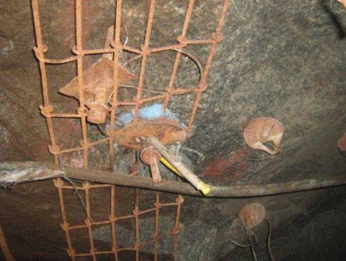
Corrosion protection Corrosion of steel rockbolts can be problematic given the potential long-term exposure to corrosive conditions in some installations (Aziz et al., 2013). This is particularly noticeable in certain shafts where accelerated corrosion is evident on all steel products in use (see Figure 5).
Resin bolts can offer excellent protection from corrosion if the tendon is fully encapsulated by the cured resin. However, when the resin is compromised with voids, poor mixing, eccentric bolt
Figure 3—Support hole diameters with 34 mm diameter bit in hard rock (Crompton, (2007)
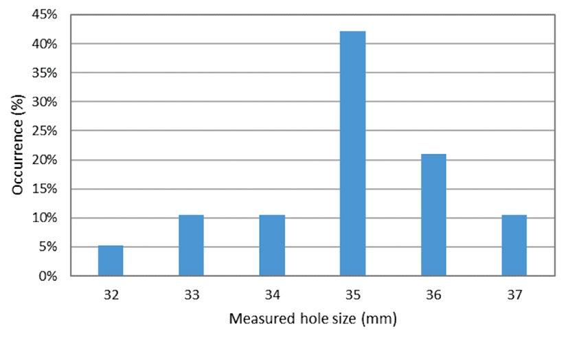
Table I Applicability of ribbed bolts in different diameter holes
Bar Ø (mm) Hole diameter (mm) 32 34 36 38
18 7 8 9 10
20 6 7 8 9
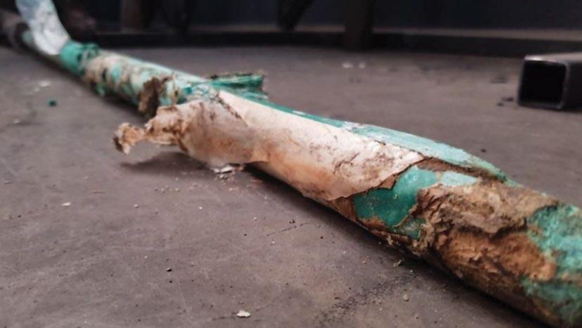
Figure 4—Gloving of common resin bolt geometry
position, or cracks, the tendon can be exposed to groundwater and other corrosive media. Contact between steel and certain rock types may also result in galvanic corrosion of the steel (Chandra and Daemen, 2009). Correctly installed resin can create a barrier between the tendon and surrounding rock, preventing this, provided that the resin completely surrounds the tendon.
This paper describes the practical approach taken to further investigate the acknowledged constraints for resin bolting applications and the development of a new resin bolt design to compensate for these.
Laboratory investigations To better understand the effect of different resin bolt designs on the quality of installed ground support, four key aspects of the performance of several tendon designs were investigated in the laboratory. Testing required the installation of a large number of resin bolt samples. In order to eliminate variability arising from inconsistencies in the installations, all samples tested were installed using an automated bolt installation machine (Figure 6). This maintained consistency during installation by automating installation factors such as rotation speed, feed speed, mixing time, and hold time.
Findings from the laboratory testing are discussed in more detail below. Centralization of resin bolts Centralization of a resin bolt in a support hole encourages consistent mixing of resin during installation, the even distribution of stress from the tendon into the resin annulus under tensile loading, and maximizes the corrosion protection ability of the resin by fully encapsulating the tendon. In order to assess the centralization of available bolt designs, 20 mm diameter paddled bolts were manufactured with 45° cropped tips and also with split tips (Figure 7), and installed into steel pipes internally threaded with a resin annulus of 9 mm.
Once the resin had cured sufficiently, samples were sliced at 50 mm intervals along their length so that the cross-section of the rockbolt and resin could be investigated. This helped determine the degree of eccentricity for both tip designs. The tests found that neither the 45° cropped tip nor the split design ensured centralization of the rockbolts during installation. Figure 8 shows the 50 mm segments cut from the distal 300 mm, the critical anchoring zone, of the resin bolts. The eccentric location of each rockbolt is sufficient to allow the bolts to contact the test pipes (and therefore the borehole walls underground) which is not desirable for corrosion protection.
Closer analysis of the test samples showed how the eccentric location of tendons within a larger diameter borehole increases the likelihood of gloving, voids, and unmixed resin (Figure 9). The large annulus to one side of the offset tendon provides a space for the resin capsule to move into without being fully shredded and mixed by the tendon.
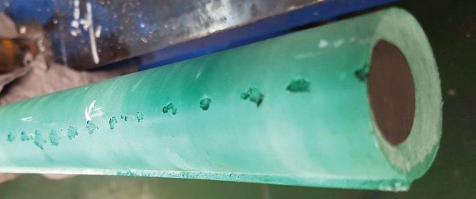
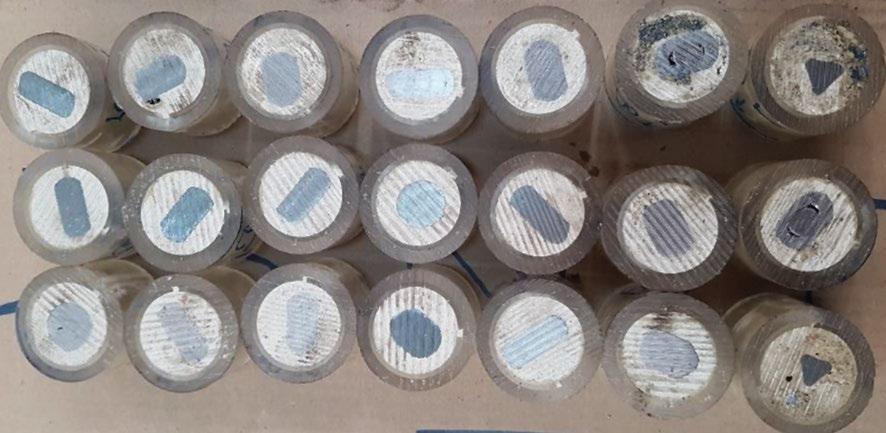
Testing was then conducted on round and ribbed bar designs by installing samples into transparent tubes with an internal diameter of 35 mm. The transparent tubes allowed observation of the tendon and resin during the installation and mixing process. After installation, the samples were removed from the tubes (Figure 10) so that the installed resin bolts could be assessed for centralization, quality of mixing, gloving, and voids. Immediately noticeable were the eccentric location of each sample and a line of voids along the resin/interface on the side where the tendon contacted the tube wall. These voids resulted in an inconsistent coating of the rockbolt by the resin, with the steel being exposed in several places along the length of the sample.
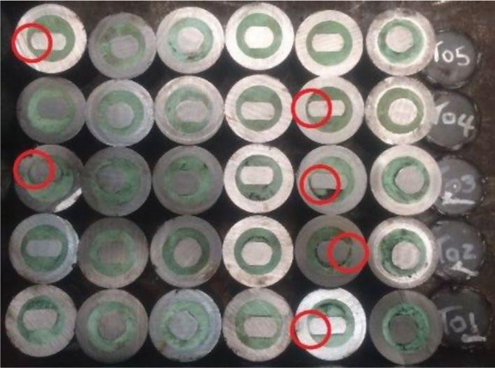
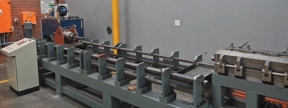
Figure 8—Eccentricity of 20 mm diameter paddled bar with 45° tip
Figure 6—Automated bolt installation machine
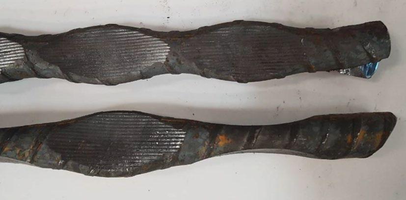

Figure 9—Poor resin mixing due to eccentric bolt location
In practice it is almost impossible to obtain a concentric alignment of the tendon and the borehole during installation. The effect is that while the tendon is rotating around its axis (shown in red in Figure 11) it is also rotating around the axis of the borehole (shown in blue in Figure 11). During installation, the tendon constantly rotates around the perimeter of the borehole and scrapes resin off this surface.
The still frame from an installation video seen in Figure 12 illustrates this phenomenon, with the ribs of the tendon visible as a line of black marks along the length of the borehole.
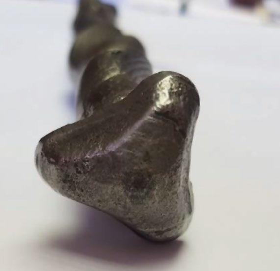
Sample tendons were manufactured with a 32 mm tri-lobe tip on the distal end of the tendon (Figure 13). The design is intended to optimize centralization of a resin bolt in boreholes with a diameter range of 32 mm to 38 mm. Samples were again installed into simulated boreholes with an internal diameter of 38 mm and then sliced into segments for analysis.
The tri-lobe tip design markedly improved both the centralization of the installed tendons and quality of the resin mixing.
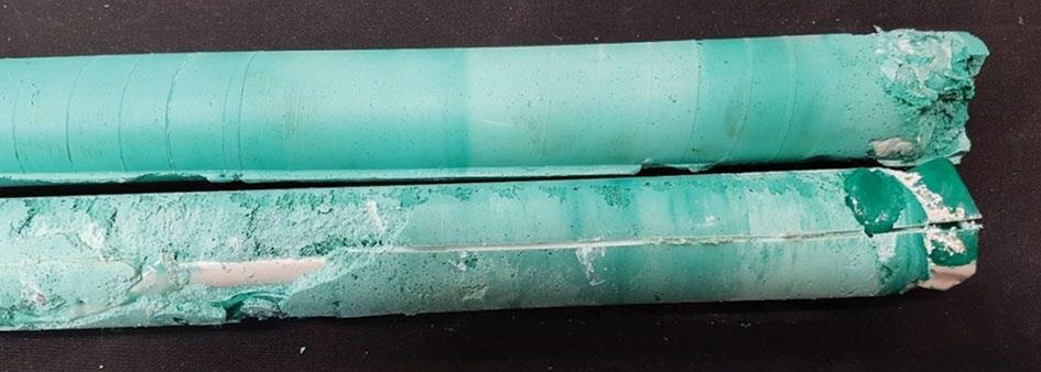
Figure 14 provides a comparison between the tendon with a tri-lobe tip (upper row of segments) and a 45° cropped tip (lower row). Gloving and mixing Gloving was prevalent in the tendons with the 45° tip, with unmixed resin being noted along the entire length of the tendons. In several instances, the tendon was fully sleeved at points along the length of the anchoring zone, completely debonding the tendon from the resin in this critical region of the installed resin bolt (Figure 15).
By comparison, the tri-lobe tip design was found to pull almost all the capsule packaging to the distal end of the hole. This is done by the packaging wrapping around the very tip of the bolt as it shreds the capsule.
Figure 16 illustrates this with a side-by-side comparison of two identical tendons, with the top tendon having a tri-lobe tip and the bottom tendon a 45° tip. The tendon with the tri-lobe tip has well mixed resin along the entire length of the resin bolt with the capsule packaging wrapped up at the distal end of the bolt. Conversely, the bottom tendon with the 45˚ tip has poorly mixed resin along its length, unmixed catalyst visible, with gloving visible and unmixed resin at the distal end of the bolt.
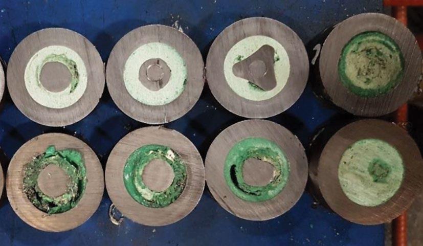
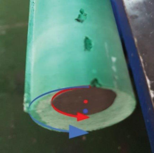
Figure 11—Eccentric location of 20 mm diameter ribbed bolt in 35 mm tube
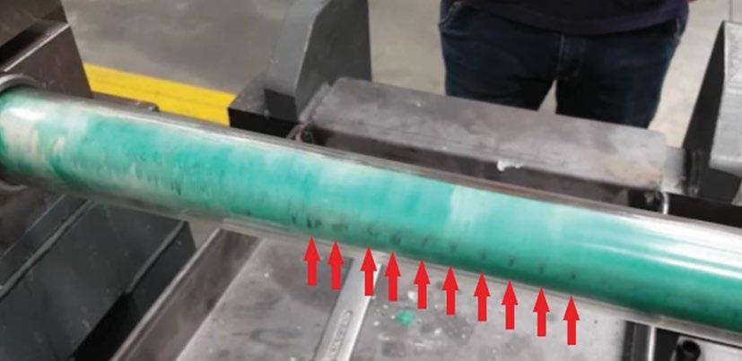
Figure 12—Scraping of resin from internal surface of the borehole
VOLUME 120 Figure 14—Resin mixing of tri-lobe tip (upper row) compared to 45° tip
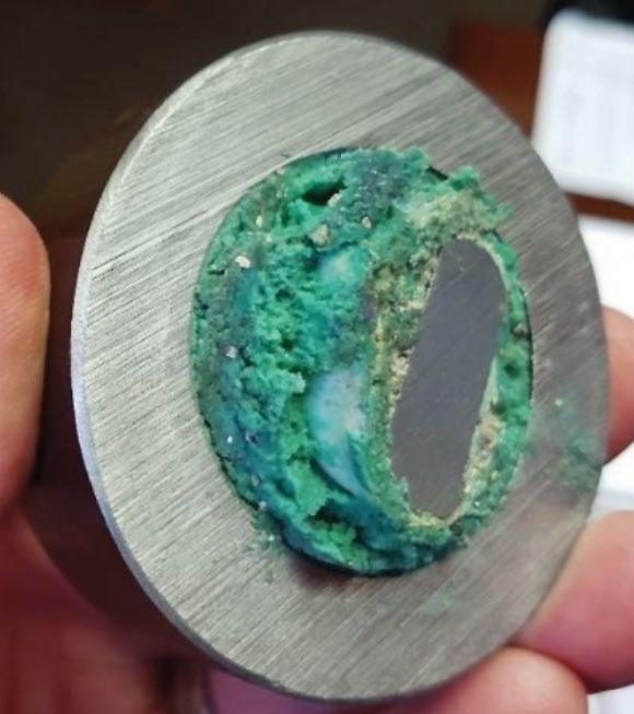
Figure 15—Gloving of test sample with 45° tip
Voids in resin To assess the efficiency with which different tendon geometries mix resin, split paddle and flat paddle designs were tested. As anticipated, both designs improve the mixing of the resin; however, both exhibited voiding around the paddled sections of the tendons (Figure 17). These voids result from curing resin being unable to flow and fill in around the rotating paddles faces during mixing. Although acceptable load capacity was still achieved when pull-testing these samples, the presence of voids may compromise the corrosion protection of the resin bolt.
To overcome the problem of voids arising from pure rotation of the resin during mixing, a design was then tested with the paddles on the bolt twisted on the bolt axis. During mixing the rotating paddles act like an auger (Figure 18), pumping the resin towards the distal end of the borehole and preventing the formation of voids behind the rotating paddles, as can be seen in Figure 19. Load testing Laboratory short encapsulation pull tests At each stage of testing, short encapsulation pull tests (SEPTs)
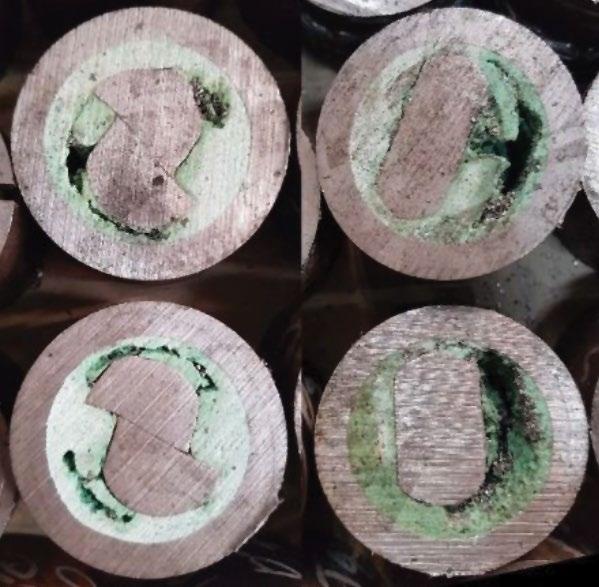
Figure 17—Voiding around flat and split paddle designs
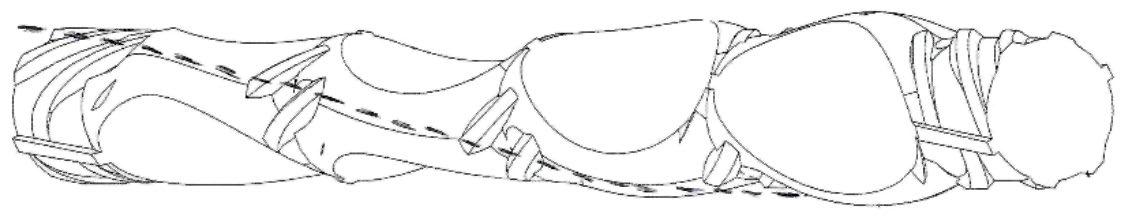
Figure 18—Voiding around flat and split paddle designs Figure 19—Good resin fill with augured paddle desig
were conducted in the laboratory to quantify the change in the bond strength arising from each design iteration, thus allowing the performance of the rockbolt to be incrementally improved with each modification. All tests were conducted in 38 mm diameter boreholes with an embedment length of 250 mm, including the tip of the tendon.
As illustrated by the performance envelopes (Figure 20), the tendon design developed through the iterative development and testing appears to provide a more consistent and stiffer anchorage at 100 kN through a combination of improved resin mixing and the tri-lobe tip compared to a conventional ribbed bar with cropped tip.
External third-party short encapsulation testing was conducted on the 20 mm diameter configuration of the tendon design with four different resins installed into 38 mm boreholes. Ten HelixBolt samples were tested with each resin and the results show that the tendon design provides similar support capacity with all four resins up to 110 kN. Performance remained consistent for three of the resins to 180 kN (Bierman, 2018). Figure 21 is an overlay of the performance envelopes for the tendon with the four different resin types.
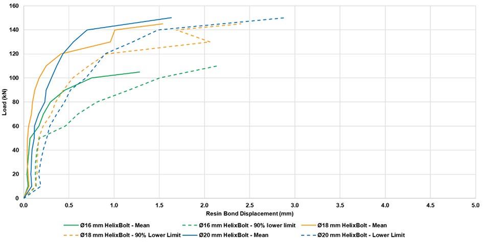
A higher resin bond stiffness is desirable in rockbolting as this prevents the opening of joints or fractures in the rock mass (Pariseau, 2007). Laboratory testing of 16, 18, and 20 mm diameter variants of the design showed that the stiffness of the resin-anchored rockbolt installed in a 38 mm hole is similar for all diameters when loaded up to 140 kN (Figure 22). The 16 mm bolt exhibited the lowest stiffness, as expected; however, the 18 mm bolts appeared to be slightly stiffer than the 20 mm bolts. This discrepancy is believed to be a result of test variability rather than bolt performance
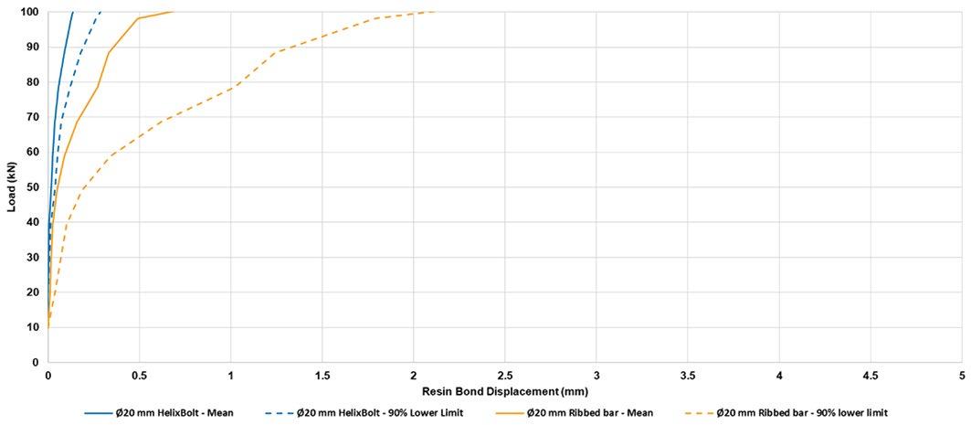
Figure 21—Laboratory SEPT results for 20 mm diameter HelixBolt with different resins in 38 mm boreholes

Figure 22—Laboratory SEPT results for different diameter HelixBolts in 38 mm holes
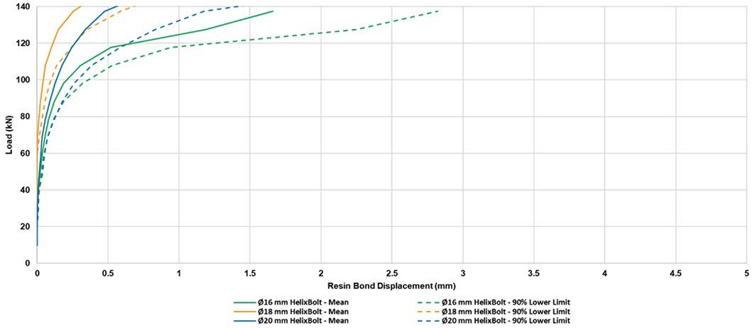
The authors attribute the consistent resin bond stiffness to the consistent geometry of the tri-lobe tip for all bolt diameters. Underground short encapsulation pull tests Subsequent to laboratory testing, underground short encapsulation testing was conducted to corroborate the laboratory results. These tests comprised five 16 mm, five 18 mm, and three 20 mm diameter samples. The rockbolts were installed into holes that ranged in measured diameter from 34.4 to 35.2 mm using a pneumatic rock drill mounted on an airleg to insert the bolts and mix the resin. The underground test results were corrected to account for stretch in the unbonded length of steel under load, and the performance envelopes derived from the results are presented in Figure 23. Note that these underground tests were terminated when the test loads reached 110 kN for the 16 mm rockbolts, 140 kN for the 18 bolts, and at 150 kN for the 20 mm bolts (Janse van Vuuren, 2017).
Comparison of the laboratory and underground SEPT results (Figure 22 and Figure 23) shows that the laboratory tests yielded higher load capacity with less deflection than the underground
tests. This is due to better control and repeatability of installation and testing parameters in the laboratory compared to testing underground.
Conclusions The aim of this research was to investigate the effect on the bond strength of different tendon designs for rockbolts anchored in larger diameter boreholes with resin capsules. Benchmark testing was conducted to confirm the behaviour during installation and resultant support capacity of conventionally used resin-anchored rockbolts in large resin annulus installations. Incremental testing and modification of different tendon geometries was conducted to document what improvements to installation reliability and quality could be achieved.
Laboratory testing found that the geometry at the tip of the rockbolt should be close to, or larger than, the diameter of the resin capsule being used with the rockbolt to effectively shred the capsule packaging and reduce the risk of gloving of the installed rockbolt.
Figure 23—Normalized underground SEPT results for different diameter HelixBolts
Centralization of the rockbolt during the mixing of the resin capsule was found to be key to improving the quality of resin mixing. Non-centred rockbolts were more prone to gloving and poor mixing due to the eccentric rotation in the support hole. Rockbolts with paddle-type tendons were found to result in the best quality resin mix (once centralized). However, deformations in a rockbolt’s cross-section create voids in the resin as the mixed resin is unable to flow in behind the paddles during rotation of the bar. These voids reduce the load-bearing capacity of the installed rockbolt and expose the steel to water and corrosive constituents in the host rock.
The addition of an auger, or helix, feature in the area of the rockbolt mixing the resin induces axial flow of the resin along the length of the rockbolt during rotation. This pushes the resin to the top of the hole, where anchoring is critical, and fills the voids created by the mixing geometry on the rockbolt.
The research led to a design that improved resin mixing, reduced the instance of gloving in applications with large resin annuli up to 11 mm (16 mm diameter bolt in 38 mm hole) and minimized voids in the resin annulus.
Laboratory and underground test results confirm that the derived rockbolt design can be installed in a resin bolting application with an 11 mm annulus and, with a 250 mm bond length, achieved loads in excess of 160 kN with an 16 mm diameter bolt, 170 kN with an 18 mm bolt, and 190 kN with a 20 mm bolt.
References
Aziz, N., Cr i , P., Nem ik, J., and H i, F.I. 2013. Rock bolt corrosion – an experimental study. Proceedings of the Coal Operators, Conference 2013. University of Wollongong, Australia. pp. 144–151.
Bierm n, R. 2018. Results of laboratory testing and underground testing of NCM HelixBolt for Impala Platinum (March 2018). Groundwork Consulting (Pty), Johannesburg, South Africa. 12 pp.
C m e , R., Mou d, R., and M Gre or, S. 2004. Investigation into the extent and mechanisms of gloving and un-mixed resin in fully encapsulated roof bolts. Proceedings of Coal 2004: Coal Operators' Conference. Aziz, N. (ed.). University of Wollongong and Australasian Institute of Mining and Metallurgy. pp. 203–214.
C n u t, I., Wi kin on, A., Proh k , G., Mni i, M., and Sin h, N. 2005. An
investigation into the support systems in South African collieries. Report no. CR231/0205/SIM302. Safety in Mines Research Advisory Committee, Johannesburg, South Africa.
Ch ndr , D. and D emen, J.J. 2009. Corrosion research on rock bolts and steel sets for sub-surface reinforcement of the Yucca Mountain repository. Report no. TR-06-
001. University of Reno, Reno, NV.
Cr i , P. 2012. Addressing resin loss and gloving issues at a mine with coal roof. Proceedings of the 12th Coal Operators’ Conference. University of Wollongong and Australasian Institute of Mining and Metallurgy. pp. 120–128
Crom ton, B. 2007. Hole survey exercise. Report no. 20070207BC. New Concept
Mining, Johannesburg, South Africa.
Ferreir , P. 2012. A perspective on underground support technologies in Southern
African platinum mines to reduce safety risks and enhance productivity. Proceedings of the Fifth International Platinum Conference: ‘A catalyst for change’, Sun City, South Africa, 17–21 September 2012. Southern African Institute of Mining and Metallurgy, Johannesburg. pp. 445–481.
J n e v n Vuuren, J. 2017. Phase 2 evaluation on resin rock support tendon performance. Report no. NCM 1708-826. Saxum Mining, Johannesburg, South Africa. 23 pp
M rk, C., Com ton, C.S., Do in r, D.R., and O er, D.C. 2003. Field performance
testing of fully grouted roof bolts. Proceedings of the 2003 SME Annual Meeting, Cincinnati. Society for Mining, Metallurgy and Exploration, Littleton, CO. pp 1–8.
P ri e u, W.G. 2007. Design Analysis in Rock Mechanics. Taylor & Francis, London.
Pur e , J., V nderm t, D., C n, M., and Cr i , P. 2016. Practical investigations into
resin anchored roof bolting parameters. Proceedings of the 16th Coal Operators' Conference. Naj Aziz, N. and Kininmonth, B. (eds.). University of Wollongong. pp. 53–63.
Sn m n, W., Ferreir , P.H., and O’Connor, D. 2011. The new generation polyester
resin capsule support for rock bolt solutions to the mining industry. Proceedings of the 6th Southern African Base Metals Conference, Phalaborwa, South Africa. Southern African Institute of Mining and Metallurgy, Johannesburg. pp. 259–272. u
A practical design approach for an improved resin-anchored tendon ACIM’s Hydraulic Fracturing Systems lead the way in the mining industry worldwide. Proudly Australian owned manufacturing company which specialise in all aspects of Hydraulic Fracturing Equipment. Systems supplied as a turnkey operation including onsite training and production support. Our systems are available in Electric 1000V, 690V, 400V or Diesel and can be customised. Our expertise in fracturing, bore hole slotting, proppant injection, gas drainage, infrastructure protection, seismicity mitigation and mining efficiency ensures client satisfaction. ACIM pride themselves in continuous development of all associated tooling to accommodate differing client needs. Our inflatable packers are of superior quality reaching the highest pressure and repetition on the market. ACIM are now conducting onsite trials for hydraulic Fracturing. u Underground or surface preconditioning. u Seismicity u Caveability For enquiries please call +61 3 9543 4470. Sales@acim.com.au www. aciminflatablepackers.com
D39 MDX BOLT PIONEERING SOLUTIONS
Designed and developed in Australia for underground hard rock mines.
The D39 Mechanical Dynamic Extra (MDX Bolt) has unparalleled “extra expansion” for extremely effective anchorage using the unique wedge design that is able to expand up to 47 mm.
The MDX Bolt is particularly suitable for seismic rock conditions with a yielding design capable of high dynamic loads establishing itselft as the benchmark in seismic ground support stability.

With a quick and simple “one pass” installation, no resin or grout, the D39 is the quickest solution to underground stability.
Also available are the 47mm MD and MDX Bolt.