ACADEMIC
& PERSONAL
Across Glacial Landscapes
Switzerland’s glaciers are rapidly receding, and forecasts suggest they will pass into history by the end of the century. This project proposes an intervention through which the ongoing process of glaciological research is enabled and performed at the architectural scale.
Cinematic Projections
Situated on a congested intersection in the heart of Mexico City, This proposal adopts a particular architectural language to create a collection of indoor and outdoor cinema spaces whilst integrating the site’s original use as a major advertising location. Through the intertwining of these two closely related functions, the site becomes a series of cinematic concourses for pedestrians.
3 Sam Martin - Architecture Portfolio


ACROSS GLACIAL LANDSCAPES

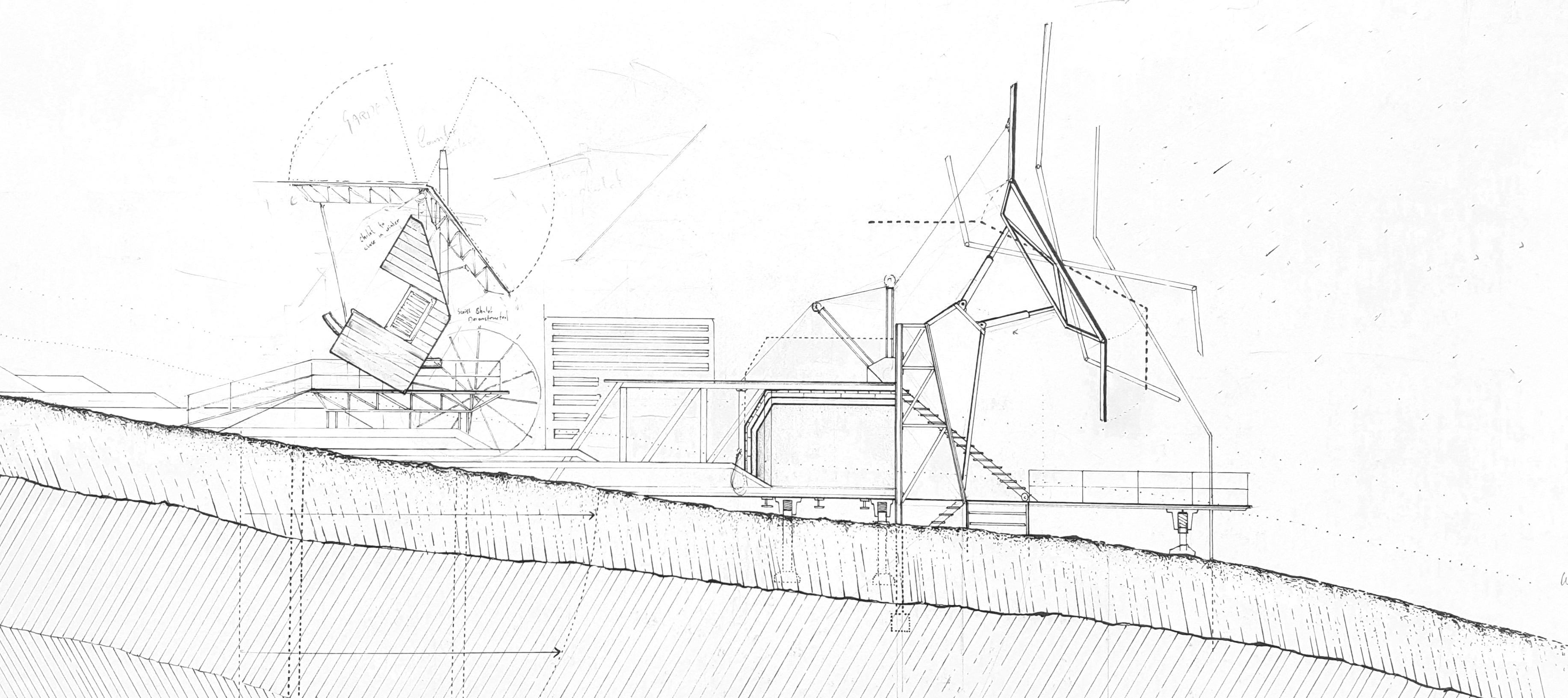
LANDSCAPE IN FLUX: PERFORMATIVE ELEMENTS
Fragments of pastiche Swiss architectural elements form a series of inhabitable spaces upon the melting glacier.
4 Sam Martin - Architecture Portfolio
01


ACROSS GLACIAL LANDSCAPES
HIKER’S CABIN: REASSEMBLY VIA MELTWATER
Kinetic architectural elements interact with the melting glacial landscape, creating a performance in sync with the seasonal accumulation and subsequent melting cycle. Inhabitable spaces are deformed to create an alternative spatial experience.
5 Sam Martin - Architecture Portfolio
01

ACROSS GLACIAL LANDSCAPES
SEASONAL SHIFTS
During winter months, the hanging structure is largely empty whilst continuing to act as a thorough-fare to the glacial museum.


6 Sam Martin - Architecture Portfolio
01

Research in Repose: Exhibition Space


ACROSS GLACIAL LANDSCAPES
RESEARCH MODULES
Research modules, whilst serving a largely technical purpose during the research season, can be deconstructed out of season to form glacial exhibition spaces.
7 Sam Martin - Architecture Portfolio
Research Capsule
01


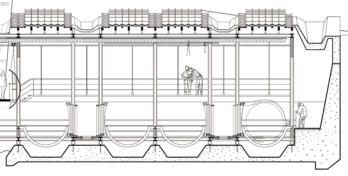

ACROSS GLACIAL LANDSCAPES
GLACIAL EXHIBITION SPACE
Celebrating the interaction between glacial research and tourism, the land-based architecture acts as a depository for the glacial research facility. The space provides accomodation for researchers, storage facility for inactive research modules, as well as the core exhibition and lecture spaces for the display of glacial research.
8 Sam Martin - Architecture Portfolio
Exposing the Capsule Hangar The capsule hangar the workings of which are visible to the public ice core archive and exhibition space partially covered by a perfomative roof; a saw-tooth profile roof is permeated by concrete snowmelt troughs and gulleys. The captured meltwater is used to lift To Research Facility Section Cut Line Snow-melt Troughs Shifting Roofscape Spatial Qualities The shifting of the roofscape reveals the internal spaces to the warming sun. The roofscape responds to the accumulation of meltwater; tiles shift upwards to expose the hangar and archival space to the warming Alpine sun. Concrete troughs accumulate snow, the melting of which collected via gulleys.
Research Module Depot
01

ACROSS GLACIAL LANDSCAPES
COMBINED PLAN
The cables supporting the tensile structure are anchored into the bedrock via a concrete splay chamber, around which the permanent inhabitable accomodation, research and exhibition spaces are nested.
9 Sam Martin - Architecture Portfolio
01

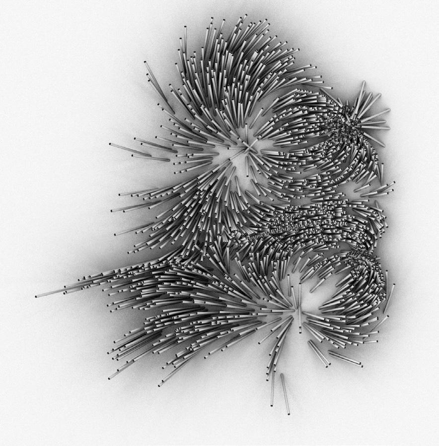


CINEMATIC PROJECTIONS
MATERIAL TESTING - LIGHT-EMITTING CONCRETE
In considering a unique articulation for cinematic and auditorium spaces for this highly congested site, material experimentation was combined with computational processes to create particular viewing angles through optical fibre-embedded concrete.
10 Sam Martin - Architecture Portfolio
02


CINEMATIC PROJECTIONS
AUDITORIUM SPACES
Acting partly as acoustic regulation, the “scaled” surfaces become a playful way to conceal projection rooms and viewing notches within the auditorium spaces.

11 Sam Martin - Architecture Portfolio
02


12 Sam Martin - Architecture Portfolio
Upper (First) Level
Lower (Ground) Level
02 CINEMATIC PROJECTIONS GA DRAWINGS & PHYSICAL MODEL
Elevation (Physical Model)

13 Sam Martin - Architecture Portfolio Vulcan Wharf • Residential, mixed-use Maggie’s Centre • Cultural Fairway • Residential WORK IN PRACTICE Sturry Street • Residential


WORK IN PRACTICE


A mixed-use scheme on a former industrial site in Stratford, London. The drawings here include elevation studies exploring materiality and form, as well as a rendered plan drawing showing ground floor layouts in relation to the public realm. The CGIs were produced externally, but in close collaboration with myself and the wider design team.
RIBA Stages 1-3
Project Duration 12 months
Location Stratford, London

14 Sam Martin - Architecture Portfolio
Category Mixed-Use
02
* CGI’s produced externally
VULCAN WHARF

WORK IN PRACTICE VULCAN WHARF
Early stage technical drawings illustrating critical spatial relationships between fenestration, FFL’s, colonnades and balconies on the eastern elevation.
15 Sam Martin - Architecture Portfolio 02

WORK IN PRACTICE
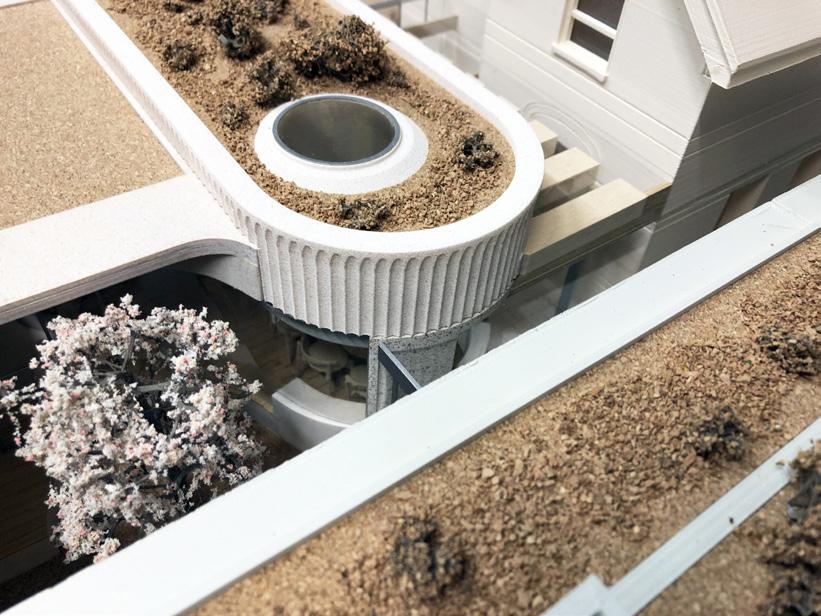
MAGGIE’S CENTRE
This is a proposed extension to an existing Maggie’s centre in Cheltenham. My involvement was assisting with the early stages of the design upto planning permission, producing drawings, visualizations, maintaining 3D & 2D drawing information and working closely with external model makers.


* Model produced externally
Category Cultural
RIBA Stages 1-3
Project Duration 6 months
Location Cheltenham
16 Sam Martin - Architecture Portfolio
02


* CGI’s produced externally
WORK IN PRACTICE
FAIRWAY HOMESTEAD
A residential project featuring a variety of tenure types, this project explored interspersing denser typologies around more intimate, “homestead” typology whereby private houses face onto a communal garden. My contribution spanned across documentation, drawing and visualization.
Category Residential
RIBA Stages 1-3
Project Duration 6 months
Location London

17 Sam Martin - Architecture Portfolio
02


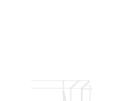
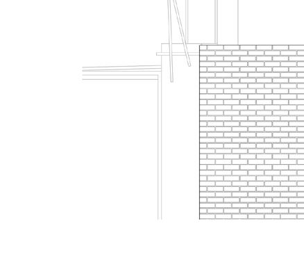


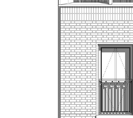


Sturry Street was a small scheme providing 7 apartments between two blocks in a conservation area. My involvement took the project through RIBA stages 3 and 4, and involved producing a fully cooridnation technical drawing package.
18 Sam Martin - Architecture Portfolio
+5.800 m AOD 00 +8.950 m AOD 01 +12.100 m AOD 02 +16.190 m AOD Sturry Villa Ridge +14.285 m AOD Sturry Villa Eaves 212100 3 212100 212101 Glass-reinforced concrete cladding units Pr_25_71_14_35 Cast stone masonry units Pr_20_93_52_13 Window Surround Cast stone sills Pr_20_93_52_12 Window Sills Clay bricks Pr_20_93_52_15 A_Brick_FlemishProjectingHeaderBond Cast stone coping units Pr_25_93_50_14 Concrete interlocking tiles Pr_25_93_72_17 uPVC Pr_65_50_35_92 COLUMN Cast stone masonry units Pr_20_93_52_13 CT02 External window systems Ss_25_30_95_26 AOV Glass-reinforced concrete (GRC) door canopies Pr_25_93_52_34 Door assembly systems Ss_25_30_20_22 COMMUNAL ENTRANCES External window systems Ss_25_30_95_26 Masonry wall leaf systems Ss_25_13_50_51 EW-A08 Balustrade and guarding systems Ss_25_60_05_05 Garden Railings Balustrade and guarding systems Ss_25_60_05_05 Balcony Railings Balustrade and guarding systems Ss_25_60_05_05 Juliet Window Balcony Construction joint sealants Pr_30_31_76_16 4940 2035 4940 Interlocking tile roofing systems Project: Client: Location Title: Current Revision Issue Date: Scale: Drawing Number: Notes Do not scale drawings. All dimensions should be checked on site. Errors to be reported to architect. To be read in conjunction with all relevant architects services and engineers drawings. Contractors, sub-contractors and suppliers must verify any critical dimensions on site prior to fabrication of any building element. Any discrepancies are to be reported o the architect. This drawing should be read in conjunction with all relevant specifications, engineers nd specialists consultants information. Any discrepancies must be reported prior to installation. Revision Project Suitability Originator Volume Level Type Role Reference Revision Date Description Issued Checked MW BIM Suitability Codes: A1, A2, An, etc. –Approved and accepted as Stage Complete, B1, B2, Bn, etc. –Partially signed-off, CR –As Construction Record documentation, S0 -Initial status WIP, S1 -Suitable for Coordination, S2 -Suitable for Information, S3 -Suitable for Review Comment, S4 -Suitable for Stage Approval, S6 –Suitable for PIM Authorisation (Information Exchanges 1-3), S7 –Suitable for AIM Authorisation (Information Exchange 6) Metropolitan Workshop 14-16 Cowcross Street London EC1M 6DG +44 (0) 20 7566 0450 www.metwork.co.uk Fire Safety Design No information in this drawing/specification should be interpreted as design related to fire safety or fire performance. As required by the Professional Indemnity market we exclude any liability whatsoever for the fire safety of buildings, products, materials or systems and assume these will be by others such as Fire Engineer and Specialist Contractor Design Disclaimers CDP Drawing Disclaimer This Design Drawing [when read with the Architectural Specification] indicates the visual intent with which the contractor must comply when undertaking the Detailed Design. The Contractor retains full responsibility for completing the Detailed Design and execution of the works [and for meeting the specified performance criteria]. 23 Aug 2021 1 50 @ A1 102000 D1 STST A DR A1 MET XX 1825 -Sturry Street 16 Sturry Street, London, E14 6DB Sturry St Villa Proposed Elevations Steadberry Restorations STAGE 4 P6 1 . Proposed Elevation -Front(East) Elevation . 1 : 50 2 . Proposed Elevation -Rear (West) Elevation . 1 : 50 P109 Mar 2021Draft issue for consultants SMRH P219 Mar 2021Stage Issue SMRH P318 June 2021Issue for Information SMRH P416 July 2021Issue for Information SMLD P513 Aug 2021Stage Issue SMLD P623 Aug 2021Stage 4 updates SMLD +12.100 +15.025 +17.000 +5.800 m AOD 00 +8.950 m AOD 01 +12.100 m AOD 02 +15.025 m AOD Plimsoll Cl Eaves +17.000 m AOD Plimsoll Cl Ridge 212200 Masonry wall leaf systems Ss_25_13_50_51 EW-B01 Interlocking tile roofing systems Ss_30_40_95_40 Natural smoke and heat exhaust ventilators Pr_70_65_04_56 Cast stone coping units Pr_25_93_50_14 Canopy systems Ss_25_50_45_10 Masonry wall leaf systems Ss_25_13_50_51 EW-B04 Masonry wall leaf systems Ss_25_13_50_51 EW-B03 Masonry wall leaf systems Ss_25_13_50_51 EW-B02 Balustrade and guarding systems Ss_25_60_05_05 Balcony Railings Balustrade and guarding systems Ss_25_60_05_05 Balcony Railings Masonry wall leaf systems Ss_25_13_50_51 EW-B06 Glass-reinforced concrete cladding units Pr_25_71_14_35 Balustrade and guarding systems Ss_25_60_05_05 Garden Railings 5278 Notes Do not scale drawings. All dimensions should be checked on site. Errors to be reported to architect. To be read in conjunction with all relevant architects services and engineers drawings. Contractors, sub-contractors and suppliers must verify any critical dimensions on site prior to fabrication of any building element. Any discrepancies are to be reported the architect. This drawing should be read in conjunction with all relevant specifications, engineers nd specialists consultants information. Any discrepancies must be reported prior to installation. Revision Date Description Issued Checked MW BIM Fire Safety Design No information in this drawing/specification should be interpreted as design related to fire safety or fire performance. As required by the Professional Indemnity market we exclude any liability whatsoever for the fire safety of buildings, products, materials or systems and assume these will be by others such as a Fire Engineer and Specialist Contractor Design Disclaimers CDP Drawing Disclaimer This Design Drawing [when read with the Architectural Specification] indicates the visual intent with which the contractor must comply when undertaking the Detailed Design. The Contractor retains full responsibility for completing the Detailed Design and execution of the works [and for meeting the specified performance criteria]. 1 . Proposed Elevation -Front (West) Elevation . 1 : 50 P109 Mar 2021Draft issue for consultants SMRH P219 Mar 2021Stage Issue SMRH P318 June 2021Issue for Information SMRH P416 July 2021Issue for Information SMLD P513 Aug 2021Stage Issue SMLD P623 Aug 2021Stage updates SMLD Category Residential RIBA Stages 3, 4 Project Duration 8 months Location Poplar London WORK IN PRACTICE 02 STURRY STREET
Po
Po
Pe
Vapou
See roof detail sheet 241000 for head condition
P
Cast
Externa
FLAT FLAT
Plas
03
TECHNICAL STUDIES
This page illustrates a few simple construction details that I produced whilst in practice. In particular, GRC & Precast window details for the former project, Sturry Street. Also shown are simple wall details which I contributed towards, in order to illustrator the various brick coursings and wall buildups.
19 Sam Martin - Architecture Portfolio layers 15mm Glasroc F Firecase Gyproc FireStrip Gyproc sealant for optimum sound insulation Partitions to be installed to manufacturer's specifications and details. Eg: refer to British Gypsum GypWall Classic : TY-701-Z1L1-06 minutes fire rating Partitions to be installed to manufacturer's specifications and details. Eg: refer to British Gypsum GypWall Classic : TY-701-Z1L1-01 Gyproc sealant for optimum sound insulation Gyproc jointing material bulk where gaps exceed 5mm 19x94mm MDF skirting +8.950 m AOD 01 H COMMUNAL STAIR Duplex (Lower Floor) GF Flat ? Concrete floor or roof deck systems Ss_30_12_85_18 FLOORS_TYPICAL Gypsum board suspended ceiling systems Ss_30_25_10_35 Partitions to be installed to manufacturer's specifications and details. Eg: refer to British Gypsum GypWall Quiet IWL TY-707Z2L2-06 60minutes Fire Rating Partition base to be installed to manufacturer's specifications and details. Eg: refer to British Gypsum GypWall Quiet IWL TY-707Z2L2-01 Annotation generally as on Detail 2 FLAT 25 25 min. F F FLAT Communal Riser Partition abutments to be installed to manufacturer's specifications and details. Eg: refer to British Gypsum GypWall Quiet IWL TY-707-Z2L2-01 Shear wall lining - Residential - x1 layer of drylining with a minimum 25mm cavity illed with mineral wool 50 +8.950 m AOD 01 H x 2 layers 15mm Glasroc F Firecase Gyproc FireStrip Gyproc sealant for optimum sound insulation Partitions to be installed to manufacturer's specifications and details. Eg: refer to British Gypsum GypWall Quiet IWL TY-707Z2L2-06 60minutes Fire Rating Stone mineral wool 33kg/m minimum density Gypsum board suspended ceiling systems Ss_30_25_10_35 Concrete floor or roof deck systems Ss_30_12_85_18 FLOORS_TYPICAL 290 45 +5.800 m AOD 00
Concrete floor or roof deck systems Ss_30_12_85_18 FLOORS_GROUND-SLAB ? Partition base to be installed to manufacturer's specifications and details. Eg: refer to British Gypsum GypWall Quiet IWL TY-707Z2L2-01 Project: Client: Location Title: Current Revision Issue Date: Scale: Drawing Number: Notes Do not scale drawings. All dimensions should be checked on site. Errors to be reported to architect. To be read in conjunction with all relevant architects services and engineers drawings. Contractors, sub-contractors and suppliers must verify any critical dimensions on site prior to fabrication of any building element. Any discrepancies are to be reported o the architect. This drawing should be read in conjunction with all relevant specifications, engineers nd specialists consultants information. Any discrepancies must be reported prior to installation. Revision Project Suitability Originator Volume Level Type Role Reference MW BIM Suitability Codes: A1, A2, An, etc. –Approved and accepted as Stage Complete, B1, B2, Bn, etc. –Partially signed-off, CR –As Construction Record documentation, S0 -Initial status or WIP, S1 -Suitable for Coordination, S2 -Suitable for Information, S3 -Suitable for Review & Comment, S4 -Suitable for Stage Approval, S6 –Suitable for PIM Authorisation (Information Exchanges 1-3), S7 –Suitable for AIM Authorisation (Information Exchange 6) Metropolitan Workshop 14-16 Cowcross Street London EC1M 6DG +44 (0) 20 7566 0450 www.metwork.co.uk Fire Safety Design No information in this drawing/specification should be interpreted as design related to fire safety or fire performance. As required by the Professional Indemnity market we exclude any liability whatsoever for the fire safety of buildings, products, materials or systems and assume these will be by others such as Fire Engineer and Specialist Contractor Design Disclaimers CDP Drawing Disclaimer This Design Drawing [when read with the Architectural Specification] indicates the visual intent with which the contractor must comply when undertaking the Detailed Design. The Contractor retains full responsibility for completing the Detailed Design and execution of the works [and for meeting the specified performance criteria]. 23 Aug 2021 1 5 @ A1 322003 D1 STST A DR ZZ MET XX 1825 -Sturry Street 16 Sturry Street, London, E14 6DB Internal Details Steadberry Restorations STAGE 4 02 Wall Head and Base Detail 1 5 3 . Typical Separating Wall/Floor Junction Junction 1 5 8 . Party Wall -Shear Wall Junction -Plan Detail 1 5 2 . 322_Section_Party Wall Deflection Head 1 5 5 . Party Wall -Ground Floor Detail 80 u e e Balc n F x ng De ail hung w ndow suppo brack P s on o SO abe anc pend ng J tt Bal o y ng e a 3 0 2 5 10 0 1 0 15 0 Externa w ndow sys ems Ss 25_30_95_26 Plas cs sheets Pr 25_57_65_60 Vapour pe meab e shee s Pr_25_57_10_94 16 5 10 SO +8 950 m AOD 01 P as cs cav y c osers P _35_90_50_64 Ex e na w ndow sys ems Ss 25_30_95_26 103 70 150 10 100 26 30 Plast cs shee s P 25_57_65_60 Vapour pe meab e sheets P _25_57_10_94 Po yp opy ene PP damp-proo courses and cav y ays P _25 57_21_64 Cas s one sills Pr 20_93_52_12 W ndow Sills W ndow s ll boards P _35_90_28_95 Seconda y s ee wo k des gn o sub con ac or s des gn P ast cs cav y c osers P _35_90_50_64 Par y F oo Ho zonta Cav y Barr er ays gn and cav y t ays ca on SO o bri s tt ng ou 1 0 Plas cs shee s Pr 25_57_65_60
permeab e shee s P _25_57_10_94
yp opy ene PP) damp-proo courses and cav y ays P _25 57_21_64
stone masonry un s P _20_93_52_13 W ndow Surround 30 25 100 10 150 50 103
o nt p as cs weep ho es P _35_90_50_62
as cs cav ty c osers P _35_90_50_64
na w ndow sys ems Ss 25_30_95_26
n e s to S uc ura Eng neer s spec ca on Vapou permeab e shee s P _25_57_10_94 O 1 0 W ndow s ll boa ds Pr_35_90_28_95 Plas cs sheets Pr 25_57_65_60 Po yp opy ene PP damp-proo cou ses and cav y t ays P _25 57_21_64 P as cs cav ty c osers P _35_90_50_64 30 25 100 10 150 50 103 45 Vapour pe meab e sheets P _25_57_10_94 Exte na w ndow sys ems Ss 25_30_95_26 Secondary s ee work des gn to sub cont acto s des gn 10 P as cs cav y c ose s Pr_35_90_50_64 Vapour pe meab e sheets Pr_25_57_10_94 Plas cs sheets Pr 25_57_65_60 15 0 1 0 10 0 2 5 3 0 SO 8 Juliet Balcony Cill 1 : 5
Cas
Perpend
P
Exte
L
1 : 5
6 . Typical W indow Head 50mm Cavity
1 : 5
5 . Typical W indow Cill 50mm Cavity
80 u e e Bal n F ng De ail hun w ndow suppo brack P s on SO abe anc pend ng tt Bal o y ng e 3 0 2 5 10 0 1 0 15 0 Externa w ndow sys ems Ss 25_30_95_26 Plas cs shee s Pr 25_57_65_60 Vapour pe meab e shee s Pr_25_57_10_94 16 5 10 SO +8 950 m AOD 01 P as cs cav y c osers P _35_90_50_64 Ex e na w ndow systems Ss 25_30_95_26 103 70 150 10 100 26 30 Plast cs shee s P 25_57_65_60 Vapour pe meab e sheets P _25_57_10_94 Po yp opy ene PP) damp-p oo courses and cav y rays P _25 57_21_64 Cas s one sills Pr 20_93_52_12 W ndow Sills W ndow s ll boards P _35_90_28_95 Secondary s ee wo k des gn o sub con rac or s des gn P ast cs cav ty c osers P _35_90_50_64 Par y F oo Ho zonta Cav y Barr er rays gn cav y ays f cat on SO T bri k e ng ou 1 0 Plas cs shee s Pr 25_57_65_60
pe meab e shee s Pr_25_57_10_94
Vapour
ypropy ene (PP damp-proof cou ses and cav y rays Pr_25 57_21_64
stone mason y un s Pr_20_93_52_13 W ndow Surround 30 25 100 10 150 50 103
pend o nt p as cs weep ho es Pr_35_90_50_62
as cs cav y c ose s Pr_35_90_50_64
w ndow sys ems Ss 25_30_95_26
nte s o S ruc u
Eng neer s spec f ca on
pe meab
shee s Pr_25_57_10_94
1 0 W ndow s ll boards P _35_90_28_95
L
a
Vapour
e
SO
cs shee s Pr 25_57_65_60 Po ypropy ene (PP damp-proof cou ses and cav y rays Pr_25 57_21_64 as cs cav y c ose s Pr_35_90_50_64 30 25 100 10 150 50 103 45 Vapou pe meab e shee s Pr_25_57_10_94 Externa w ndow sys ems Ss 25_30_95_26 Seconda y stee work des gn o sub con rac o s des gn 10 P as cs cav y c ose s Pr_35_90_50_64 Vapou permeab e sheets Pr_25_57_10_94 Plas cs shee s Pr 25_57_65_60 15 0 1 0 10 0 2 5 3 0 SO 8 Juliet Balcony Cill 1 : 5 6 . Typical W indow Head 50mm Cavity 1 : 5 5 . Typical W indow Cill 50mm Cavity 1 : 5
241000 for head condition SO 10 80 235 Plastics cavity closers Pr_35_90_50_64 Cast stone sills Pr_20_93_52_12 Window Sills Cast stone sills Pr_20_93_52_12 Window Sills 30 25 100 10 150 70 103 External window systems Ss_25_30_95_26 Vapour permeable sheets Pr_25_57_10_94 Plastics sheets Pr_25_57_65_60 10 SO Vapour permeable sheets Pr_25_57_10_94 Plastics sheets Pr_25_57_65_60 Plastics sheets Pr_25_57_65_60 45 103 70 150 10 100 25 30 Cast stone sills Pr_20_93_52_12 Window Sills Plastics cavity closers Pr_35_90_50_64 Polypropylene (PP) damp-proof courses and cavity trays Pr_25_57_21_64 Window sill boards Pr_35_90_28_95 External window systems Ss_25_30_95_26 Cast stone sills Pr_20_93_52_12 Window Sills Secondary steelwork design to sub contractor's design SO 10 Pr_25_57_06_56 (150mm) Plastics cavity closers Pr_35_90_50_64 225 10 Lintels to Structural Engineer's specification Cast stone sills Pr_20_93_52_12 Window Sills External window systems Ss_25_30_95_26 Pistol Brick SO To brick setting out 10 Plastics sheets Pr_25_57_65_60 SO 10 Window sill boards Pr_35_90_28_95 Plastics sheets Pr_25_57_65_60 30 25 100 10 150 50 103 45 Secondary 10 SO 203 80 Notes Do not scale drawings. All dimensions should be checked on site. Errors to be reported to architect. To be read in conjunction with all relevant architects services and engineers drawings. Contractors, sub-contractors and suppliers must verify any critical dimensions on site prior to fabrication of any building element. Any discrepancies are to be reported o the architect. This drawing should be read in conjunction with all relevant specifications, engineers nd specialists consultants information. Any discrepancies must be reported prior to installation. Revision Date Description Issued Checked MW BIM Suitability Codes: A1, A2, An, etc. –Approved and accepted as Stage Complete, Fire Safety Design No information in this drawing/specification should be interpreted as design related to fire safety or fire performance. As required by the Professional Indemnity market we exclude any liability whatsoever for the fire safety of buildings, products, materials or systems and assume these will be by others such as a Fire Engineer and Specialist Contractor Design Disclaimers CDP Drawing Disclaimer This Design Drawing [when read with the Architectural Specification] indicates the visual intent with which the contractor must comply when undertaking the Detailed Design. The Contractor retains full responsibility for completing the Detailed Design and execution of the works [and for meeting the specified performance criteria]. 1 . Typical Window Jamb 70mm Cavity . 1 : 5 2 . Typical Window Cill 70mm Cavity . 1 : 5 3 . Typical Window Head 70mm Cavity . 1 : 5 6 . Typical Window Head 50mm Cavity . 1 : 5 5 . Typical Window Cill 50mm Cavity . 1 : 5 4 . Typical Window Jamb 50mm Cavity . 1 : 5 0125 June 2021Issue for Information ADLD 0213 Aug 2021Stage 4 Issue SMLD 0323 Aug 2021Stage 4 updates SMLD 4 External wall sheathing systems Ss_25_25_95_28 Light steel wall framing systems Ss_25_10_32_45 Gypsum plasterboards Pr_25_71_52_38 Mineral wool slab insulation Pr_25_57_06_56 (150mm) Clay bricks Pr_20_93_52_15 A_Brick_StretcherBond Masonry wall leaf systems Ss_25_13_50_51 EW-A01 103 50 150 10 100 25 30 Gypsum board wall lining systems Ss_25_25_45_35 Plastics sheets Pr_25_57_65_60 Vapour permeable sheets Pr_25_57_10_94 +8.950 m AOD 01 I Masonry wall leaf systems Ss_25_13_50_51 EW-A02 Mineral wool slab insulation Pr_25_57_06_56 (150mm) Clay bricks Pr_20_93_52_15 A_Brick_FlemishProjectingHeaderBond Light steel wall framing systems Ss_25_10_32_45 External wall sheathing systems Ss_25_25_95_28 20 103 50 150 10 100 25 30 Gypsum board wall lining systems Ss_25_25_45_35 Gypsum plasterboards Pr_25_71_52_38 Plastics sheets Pr_25_57_65_60 Vapour permeable sheets Pr_25_57_10_94 20 103 70 150 10 Notes Do not scale drawings. All dimensions should be checked on site. Errors to be reported to architect. To be read in conjunction with all relevant architects services and engineers drawings. Contractors, sub-contractors and suppliers must verify any critical dimensions on site prior to fabrication of any building element. Any discrepancies are to be reported the architect. This drawing should be read in conjunction with all relevant specifications, engineers nd specialists consultants information. Any discrepancies must be reported prior to installation. Revision Date Description Issued Checked Fire Safety Design No information in this drawing/specification should be interpreted as design related to fire safety or fire performance. As required by the Professional Indemnity market we exclude any liability whatsoever for the fire safety of buildings, products, materials or systems and assume these will be by others such as a Fire Engineer and Specialist Contractor Design Disclaimers CDP Drawing Disclaimer This Design Drawing [when read with the Architectural Specification] indicates the visual intent with which the contractor must comply when undertaking the Detailed Design. The Contractor retains full responsibility for completing the Detailed Design and execution of the works [and for meeting the specified performance criteria]. 1 . EW-A01 . 1 : 10 2 . EW-A02 . 1 : 10 3 . EW-A03 . 0104 June 2021Issue for Information SMRH 0213 Aug 2021Stage 4 Issue SMLD 0323 Aug 2021Stage 4 updates SMLD REFER TO SHEET 211204
See roof detail sheet
03
TECHNICAL STUDIES
Further details including a study of the balcony terrace, which uses solid precast columns and capping stones, as well as GRC columns which conceal structural loadbearing columns within. On the right, a parapet condition draining onto a flat roof.
20 Sam Martin - Architecture Portfolio
7 7 71 100 150 143 E E 7 7 143 COLUMN Cast stone masonry units Pr_20_93_52_13 CT01 Cast stone coping units Pr_25_93_50_14 F F 7 Portland Concrete +12.100 m AOD 02 +14.285 m AOD Sturry Villa Eaves 70 55 Clay bricks Pr_20_93_52_15 A_Brick_SoldierBond 665 Refer to Detail 1/241000 for typical parapet details - this drawing is indicate stonework intent only +12.100 m AOD 02 +14.285 m AOD Sturry Villa Eaves 50 55 665 Clay bricks Pr_20_93_52_15 A_Brick_SoldierBond 100 50 Refer to Detail 1/241000 for typical parapet details - this drawing is indicate stonework intent only 100 150 50 Project: Client: Location Title: Current Revision Issue Date: Scale: Drawing Number: Notes Do not scale drawings. All dimensions should be checked on site. Errors to be reported to architect. To be read in conjunction with all relevant architects services and engineers drawings. Contractors, sub-contractors and suppliers must verify any critical dimensions on site prior to fabrication of any building element. Any discrepancies are to be reported the architect. This drawing should be read in conjunction with all relevant specifications, engineers nd specialists consultants information. Any discrepancies must be reported prior to installation. Revision Project Suitability Originator Volume Level Type Role Reference Revision Date Description Issued Checked MW BIM Suitability Codes: A1, A2, An, etc. –Approved and accepted as Stage Complete, B1, B2, Bn, etc. –Partially signed-off, CR –As Construction Record documentation, S0 -Initial status or WIP, S1 -Suitable for Coordination, S2 -Suitable for Information, S3 -Suitable for Review & Comment, S4 -Suitable for Stage Approval, S6 –Suitable for PIM Authorisation (Information Exchanges 1-3), S7 –Suitable for AIM Authorisation (Information Exchange 6) Metropolitan Workshop 14-16 Cowcross Street London EC1M 6DG +44 (0) 20 7566 0450 www.metwork.co.uk Fire Safety Design No information in this drawing/specification should be interpreted as design related to fire safety or fire performance. As required by the Professional Indemnity market we exclude any liability whatsoever for the fire safety of buildings, products, materials or systems and assume these will be by others such as Fire Engineer and Specialist Contractor Design Disclaimers CDP Drawing Disclaimer This Design Drawing [when read with the Architectural Specification] indicates the visual intent with which the contractor must comply when undertaking the Detailed Design. The Contractor retains full responsibility for completing the Detailed Design and execution of the works [and for meeting the specified performance criteria]. 23 Aug 2021 1 5 @ A1 212102 D1 STST A DR A1 MET ZZ 1825 -Sturry Street 16 Sturry Street, London, E14 6DB Wall Details -Balcony -A1 Steadberry Restorations STAGE 4 03 4 . A1 -Balcony Plan 02 . 1 : 5 3 . A1 -Balcony Plan -01 . 1 : 5 5 . A1 -Balcony Plan -03 . 1 : 5 2 . A1 -Balcony Section 02 . 1 : 5 1 . A1 -Balcony Section 01 1 : 5 0118 June 2021Issue for Information SMRH 0213 Aug 2021Stage Issue SMLD 0323 Aug 2021Stage updates SMLD 7 7 71 100 150 Portland Concrete 143 E E 7 7 143 COLUMN Cast stone masonry units Pr_20_93_52_13 CT01 Cast stone coping units Pr_25_93_50_14 F F 7 Portland Concrete +12.100 m AOD 02 +14.285 m AOD Sturry Villa Eaves 70 55 Clay bricks Pr_20_93_52_15 A_Brick_SoldierBond 665 Refer to Detail 1/241000 for typical parapet details - this drawing is indicate stonework intent only 50 55 Clay bricks Pr_20_93_52_15 A_Brick_SoldierBond 100 150 50 Project: Client: Location Title: Current Revision Issue Date: Scale: Drawing Number: Notes Do not scale drawings. All dimensions should be checked on site. Errors to be reported to architect. To be read in conjunction with all relevant architects services and engineers drawings. Contractors, sub-contractors and suppliers must verify any critical dimensions on site prior to fabrication of any building element. Any discrepancies are to be reported o the architect. This drawing should be read in conjunction with all relevant specifications, engineers nd specialists consultants information. Any discrepancies must be reported prior to installation. Revision Project Suitability Originator Volume Level Type Role Reference MW BIM Suitability Codes: A1, A2, An, etc. –Approved and accepted as Stage Complete, B1, B2, Bn, etc. –Partially signed-off, CR –As Construction Record documentation, S0 -Initial status or WIP, S1 -Suitable for Coordination, S2 -Suitable for Information, S3 -Suitable for Review Comment, S4 -Suitable for Stage Approval, S6 –Suitable for PIM Authorisation (Information Exchanges 1-3), S7 –Suitable for AIM Authorisation (Information Exchange 6) Metropolitan Workshop 14-16 Cowcross Street London EC1M 6DG +44 (0) 20 7566 0450 www.metwork.co.uk Fire Safety Design No information in this drawing/specification should be interpreted as design related to fire safety or fire performance. As required by the Professional Indemnity market we exclude any liability whatsoever for the fire safety of buildings, products, materials or systems and assume these will be by others such as a Fire Engineer and Specialist Contractor Design Disclaimers CDP Drawing Disclaimer This Design Drawing [when read with the Architectural Specification] indicates the visual intent with which the contractor must comply when undertaking the Detailed Design. The Contractor retains full responsibility for completing the Detailed Design and execution of the works [and for meeting the specified performance criteria]. 23 Aug 2021 1 5 @ A1 212102 D1 STST A DR A1 MET ZZ 1825 -Sturry Street 16 Sturry Street, London, E14 6DB Wall Details -Balcony -A1 Steadberry Restorations STAGE 4 03 4 . A1 -Balcony Plan 02 . 1 : 5 3 . A1 -Balcony Plan -01 . 1 : 5 5 . A1 -Balcony Plan -03 . 1 : 5 2 . A1 -Balcony Section 02 . 1 : 5 Section 01 . 1 : 5 +15.025 m AOD Plimsoll Cl Eaves 1 Minimum Finished Fall of 1:80 towards rainwater outlet Radmat Eshaflex 370 FireSafe Cap Sheet Radmat Vidatop Selfadhered base layer on a plywood substrate Fixings and Flashings to manufacturer's details Plastics cavity closers Pr_35_90_50_64 Party Floor Horizontal Cavity Barrier Pr_25_57_08_75 Reinforced bitumen roofing sheets Flat board roof deck systems Ss_30_40_10_30 ROOF_STURRY-VILLA 150 50 Cast stone coping units Pr_25_93_50_14 Polypropylene (PP) damp-proof courses and cavity trays Pr_25_57_21_64 Minimum Finished Fall of 1:80 towards rainwater outlet nom high point of falls Notes Do not scale drawings. All dimensions should be checked on site. Errors to be reported to architect. To be read in conjunction with all relevant architects services and engineers drawings. Contractors, sub-contractors and suppliers must Revision Date Description Issued Checked Fire Safety Design No information in this drawing/specification as design related to fire safety the Professional Indemnity market whatsoever for the fire safety systems and assume these Disclaimers 1 . 241-B1-Roof-01-Parapet-Flat Roof . 1 : 5 2 . 241-B1-Roof-02-Plimsoll 0116 July 2021Issue for Information ADLD 0213 Aug 2021Stage 4 Issue SMLD 0320 Aug 2021Stage 4 updates SMLD 0423 Aug 2021Stage 4 updates SMLD
 Sam Martin
Architecture Portfolio
MArch Bartlett Application


 Sam Martin
Architecture Portfolio
MArch Bartlett Application


