My name is Selina Almadanat and I am a recently graduated Architectural Studies student from the University of Toronto (UofT). I am a Canadian with Jordanian and Lebanese roots, and am currenly living in Toronto, Ontario. I graduated from UofT with High Distinction, where I completed an Honours Bachelor of Arts in Architectural Studies, with a specialization in Technology of Architecture, Landscape, and Urbanism. Additionally, I completed a Certification in Sustainability of the Built Environment.
As an architectural designer and environmentalist, I believe that a focus on people and local culture is the key to truly creating beautiful and sustainable designs. Learning from existing environments and social contexts is crucial to creating meaningful and lasting architecture. This philosophy guided my Undergraduate Thesis titled, “Lessons from the Vernacular: Integrating Levantine Vernacular Architecture for the Sustainable Reconstruction of Beirut.”
Having recently graduated, I am eager to continue growing professionally and personally, I have a strong desire to explore new ideas, techniques, and learn from others’ experiences.. Alongside architecture, I am passionate about digital fabrication, woodworking, music, and making and designing things through all mediums.

Curriculum Vitae 2024
EDUCATION
University of Toronto 2020-2024
HBA Architecural Studies
Specialist in Technology of Architecture, Landscape, and Urbanism
Cerificate in Sustainability of the Built Environment
Graduated with High Distinction (3.95 CGPA)
Daniels FacultyAcademic MeritAward (June 2024)
James and Hilda WarwickAward (June 2024)
GEMS International School Al Khail 2014-2020
International Baccalaureate Diploma Programme (IBDP)
Predicted 44 points, achieved 39
Student Body President
Academic Honours
SeniorAcademic Excellence in Physics, Chemistry, Mathematics, Global Politics
WORK EXPERIENCE
CNC Lab Technologist
Setup and review RhinoCAM and 3D model files from students for CNC milling submissions
Schedule prepared files and work with students to run CNC file submissions
Set up and run the CNC Milling machine
Design Research Intern at gh3* Architects
2023-2024
Completed research focusing on how a site-condition-specific approach can influence the plant species integrated within the project
Developed a botanical knowledge base on Tableau Public with different characteristics to be applied to the process of selecting plants and designing a landscape
Fabrication Team Member: Aeolian Soundscape Project
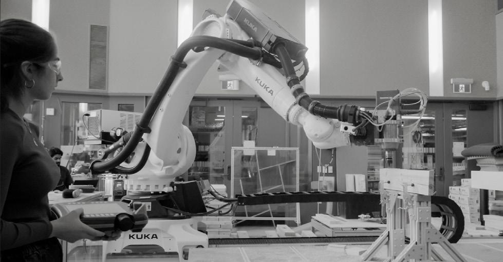
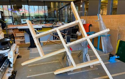
Conducted timber Fabrication in the Daniels robotic Fabrication Lab
6-Axis milling using KUKA Robot Arm
Treating and Finishing wood beams, followed by Pre-Assembly of the structure at Daniels
Onsite Assembly at Trillium Park at Ontario Place
SKILLS
FABRICATION
3D Printing
CNC Milling
Wood Working
AutoCAD Enscape Microsoft Office
Blender
4-axis Milling
2023
2023
Precedent:
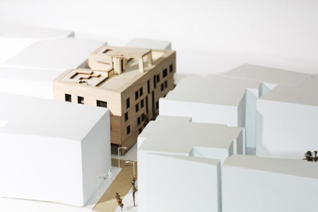
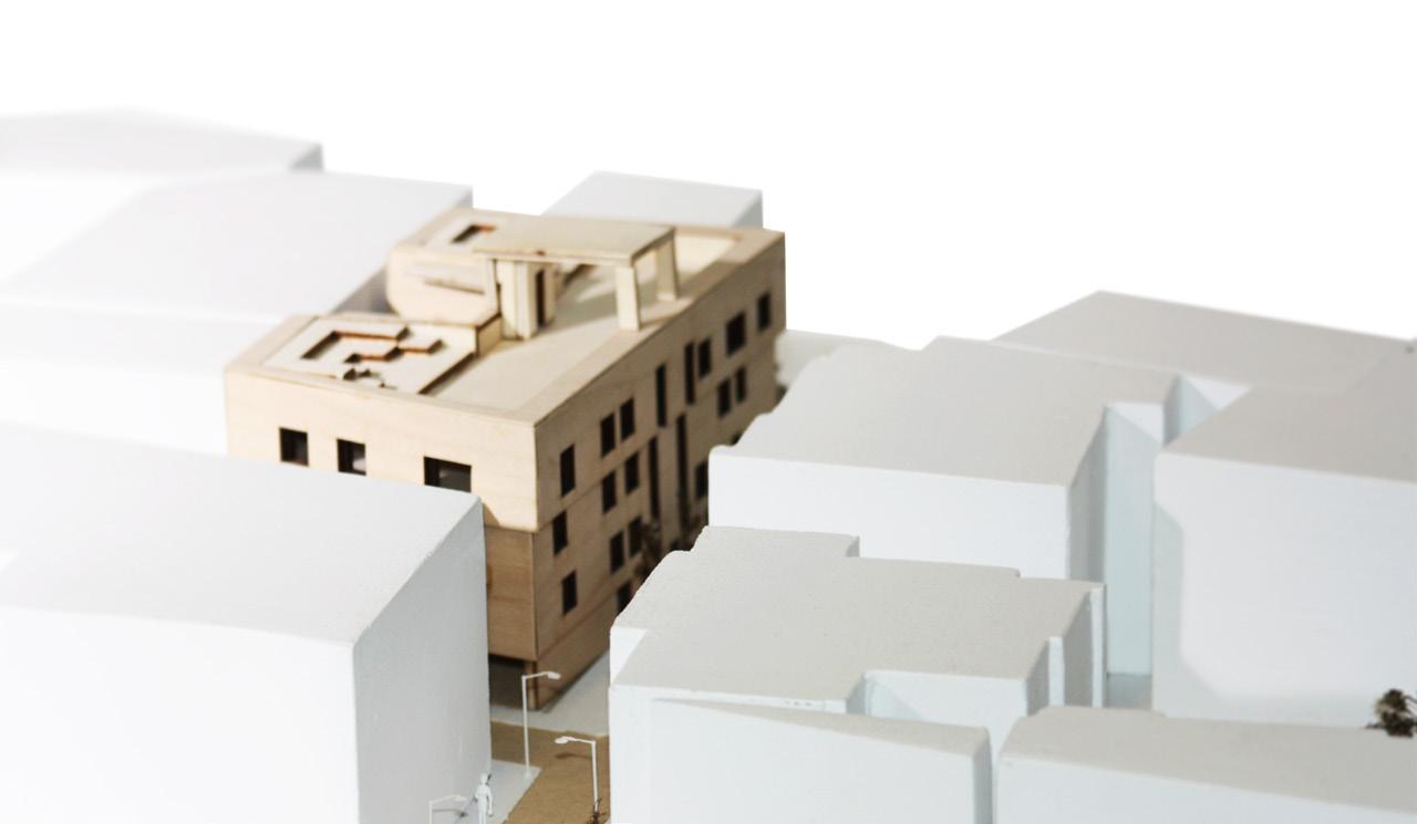
Lessons from the Vernacular: Residential Complex
Year 2023
Location Gemmayzeh, Beirut, Lebanon
The aftermath of the Beirut Port explosion (2020) intensified issues regarding energy usage and gentrification, along with destruction of the city’s heritage spaces. Despite the devastation, there lies an opportunity to reconsider the standard of building through the integration of Levantine vernacular architecture within present-day construction. This offers an environmentally and socially sustainable approach to reconstructing Beirut’s neighborhoods while conserving the city’s heritage.
Based off research on vernacular Levantine construction and design, 3 key strategies were formulated to integrate vernacular techniques into modern construction. This strategy of building has the opportunity to extend beyond the realm of post-disaster building and the four proposed strategies may be utilized to serve future construction projects. The developed strategies were realized through the design of a residential complex in Beirut, acting as a model for future construction in the country.
This design acts as a proof of concept for the argument that modern methods of design should learn from vernacular strategies of building. Proof of value in these vernacular techniques may encourage investigations into the vernacular architecture of other regions, inspiring more sustainable and culturally relevant forms of building.
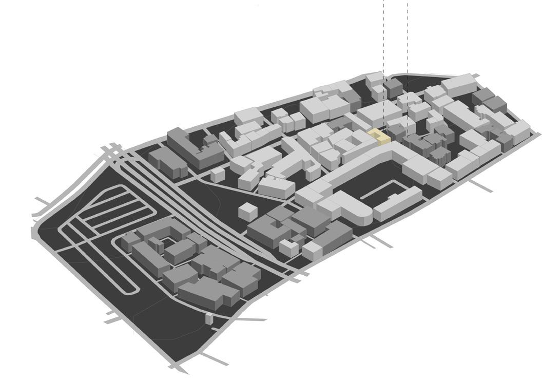
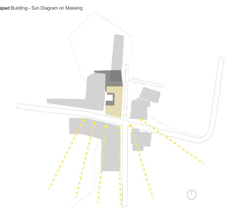
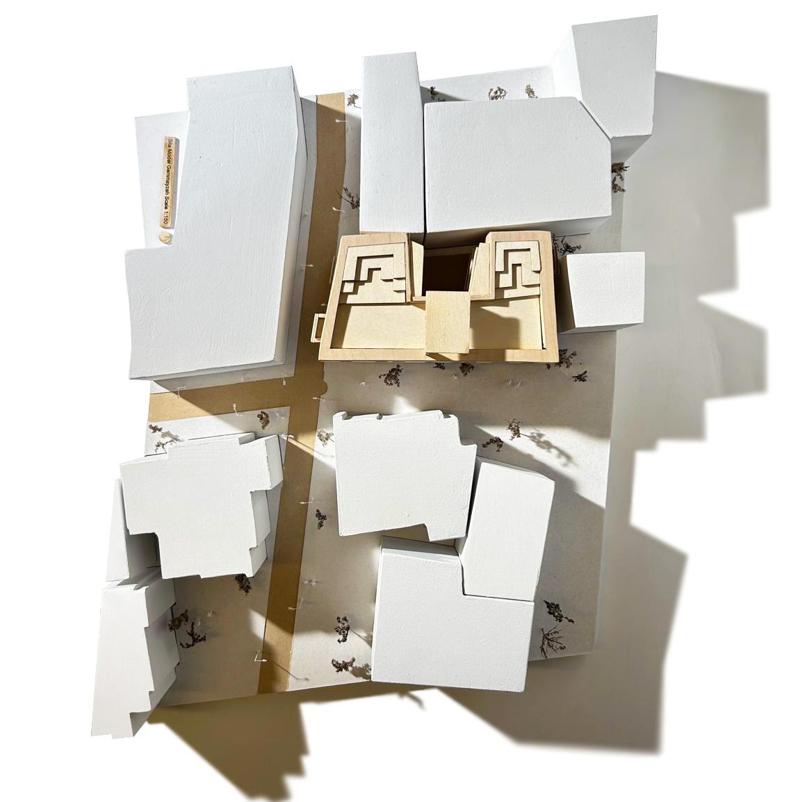
The Gemmayzeh neighbourhood is 600m away from the site of the blast. There are many heritage buildings, so severe damage to the homes would be harder and more expensive to repair.
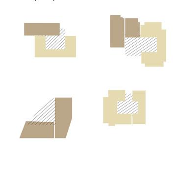

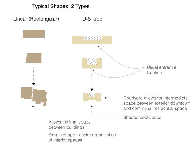
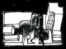
LEFT: Site form analysis, and selected building analysis. As a proposed model for rebuilding, the complex was designed to fit the plot of a pre-existing site
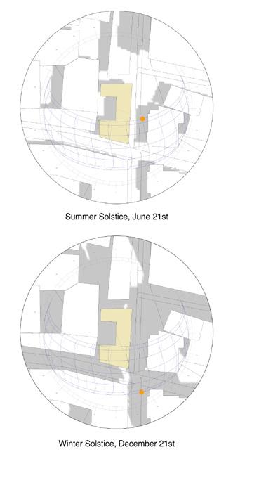
RIGHT TOP: Sun and shadow analysis of the selected building’s site
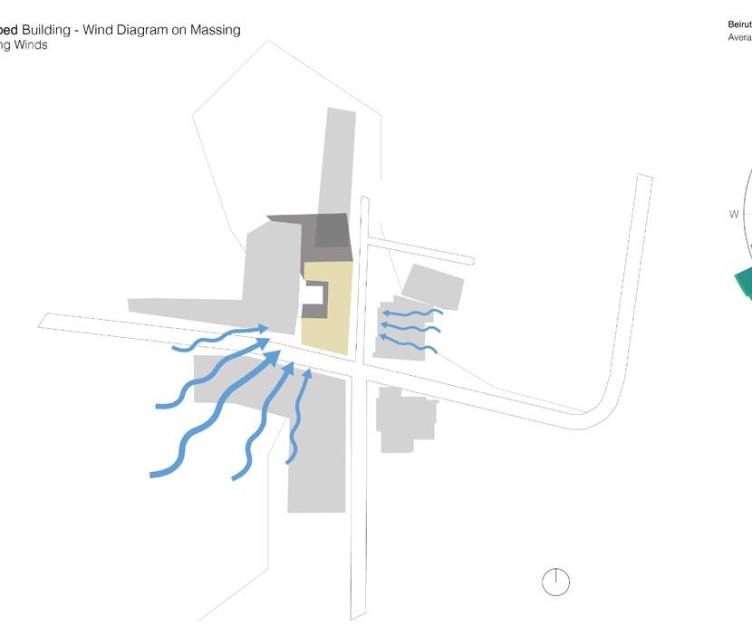
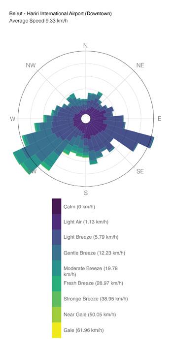
RIGHT BOTTOM: Wind Diagram on selected building’s site

Site and Area
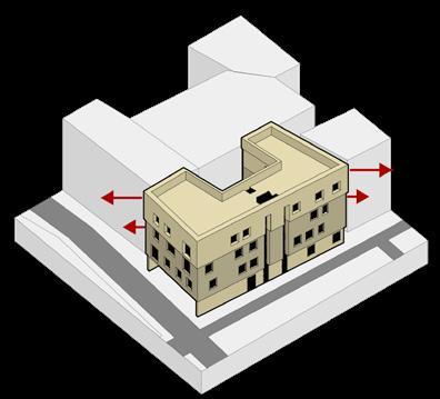
Building form is based off the pre-existing damaged building’s lot shape
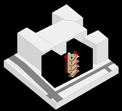
Circulation through Core
Circulation is added, wheelchair accessible as well through an elevator
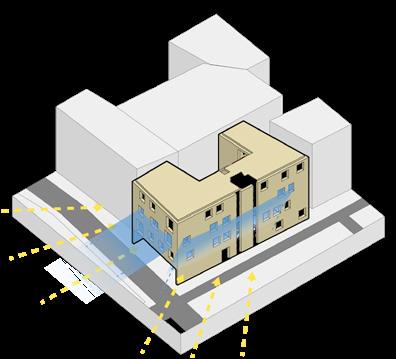
Ventilation and Lighting
Windows and opening are placed to receive sunlight and allow for cross ventilation
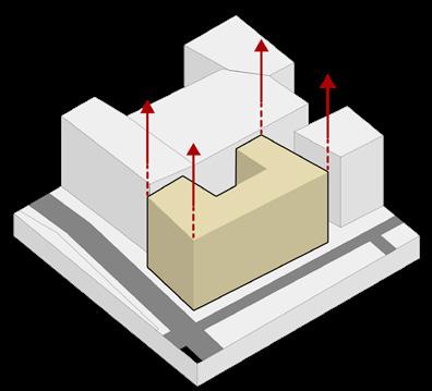
Vertical Form
The building form is extruded four storeys from the ground plane
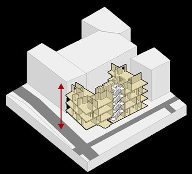
Floor plans and Layout
Four floors are placed with the circulation tying it all together through a central core
Façade
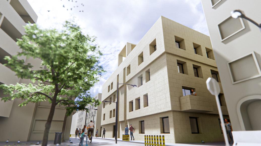
The Exterior façade is extruded away from the building at two different levels

In order to develop the 3 key design strategies used to design a new model for building, vernacular and traditional levantine homes were cataloged and studied. The typologies whose strategies were the most relevant to modern society were the Gallery House and the Liwan. From this, the 3 key design strategies were implemented into the project concerning layout, sunlighting, and ventilation
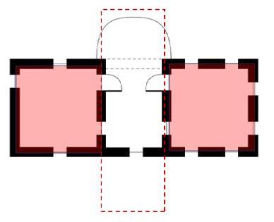
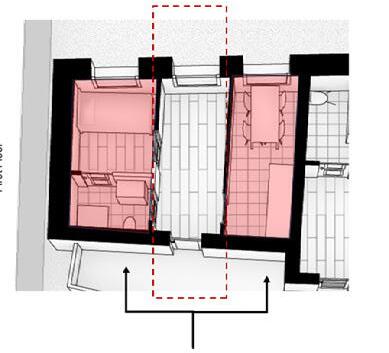
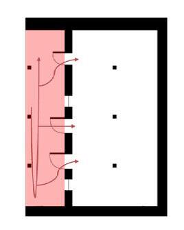
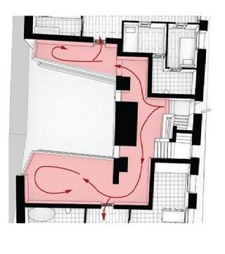
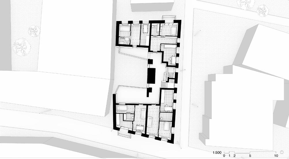
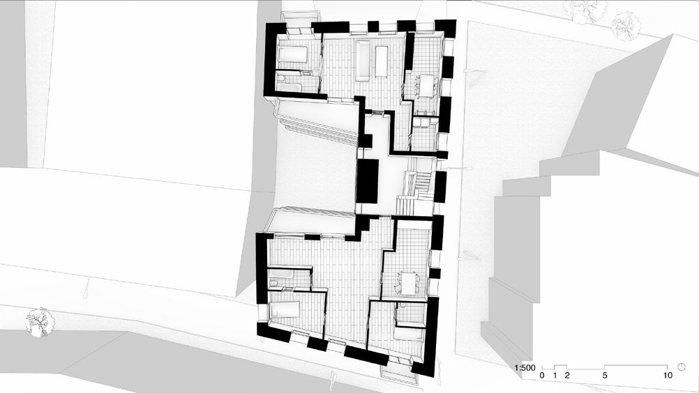
LEFT TOP: Sample of own vernacular research and diagrams.
LEFT BOTTOM: Example of layout strategy used in floorplans.
RIGHT: Two floor plans of the residential complex. The building has five floors including the roof.
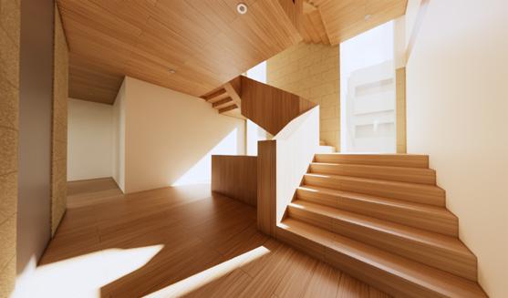
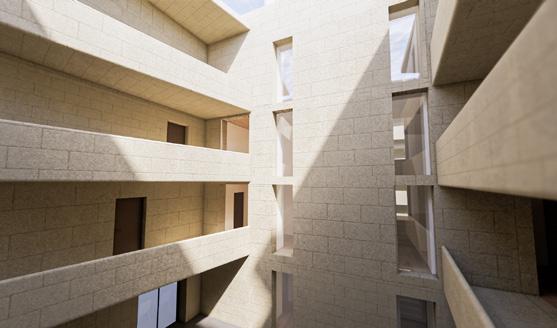
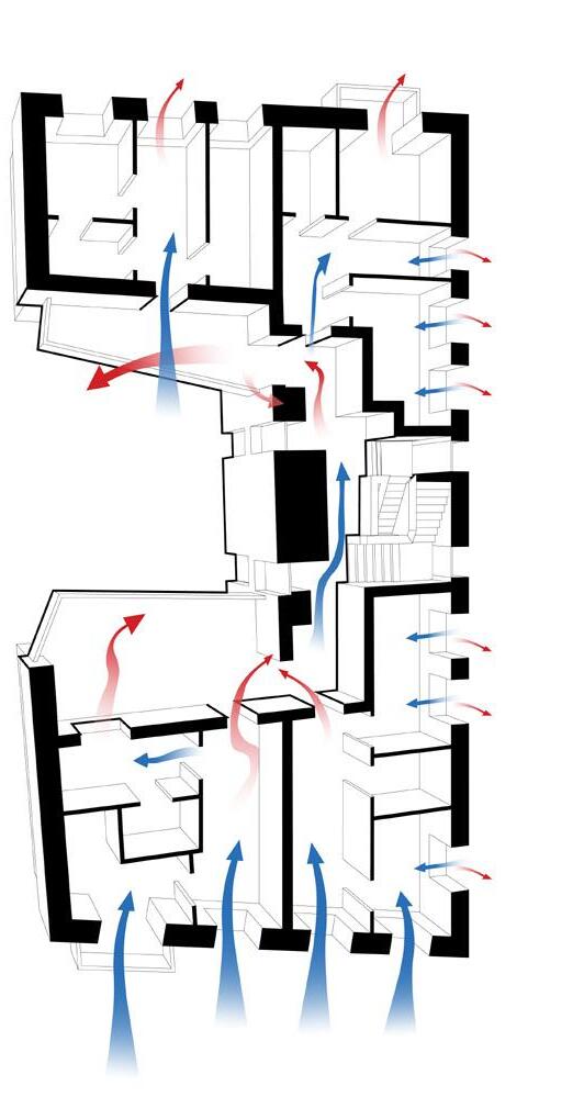
Ventilation and Daylighting: The ventilation strategy follows a simple formula. It involves orienting windows and openings in the direction of the prevailing winds in order to allow cross ventilation within the building space.
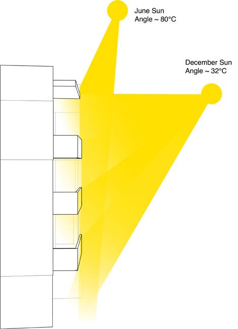
The shading and daylighting techniques are influenced by those found in vernacular levantine construction. Like the Gallery House typology, the balconies shade the courtyard in summer and allow sunlight in during winter. (1). The stepped façade provides a similar effect to the overhangs of the Central Hall House typology and windowsills. (2).

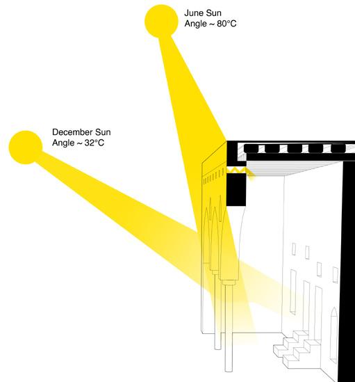
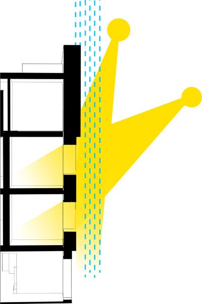

Insulation and Heat Gain: A full exploration of the insulation and heat gain strategies lay beyond the scope of the intial thesis. Much of this strategy is speculative, yet draws upon the techniques found in levante vernacular technologies.
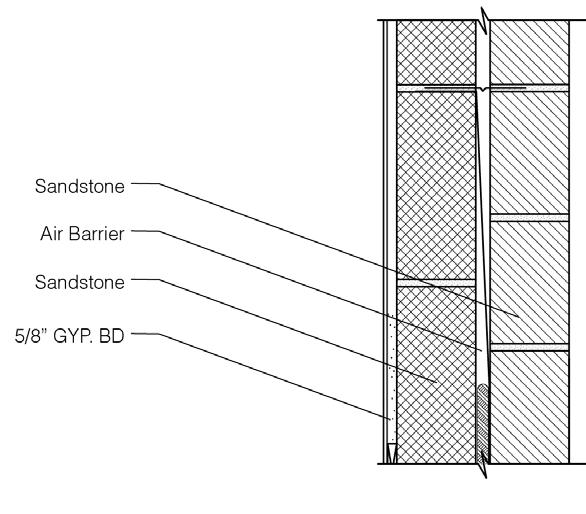
Similar to the traditional wall, the exterior walls of the housing complex are comprised of two layers of sandstone, with an air barrier in between. With an additional gypsum board, the brings the thermal transmittance of the wall to lay below the City’s maximum allowable wall transmittance value.
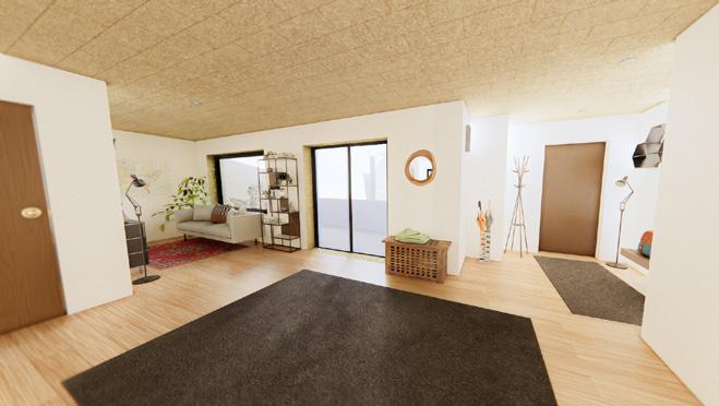
Hardwood floors are used for flooring as they absorb heat and release it slowly over time. Some of the native, and usable trees are oak, pine, and cedar.

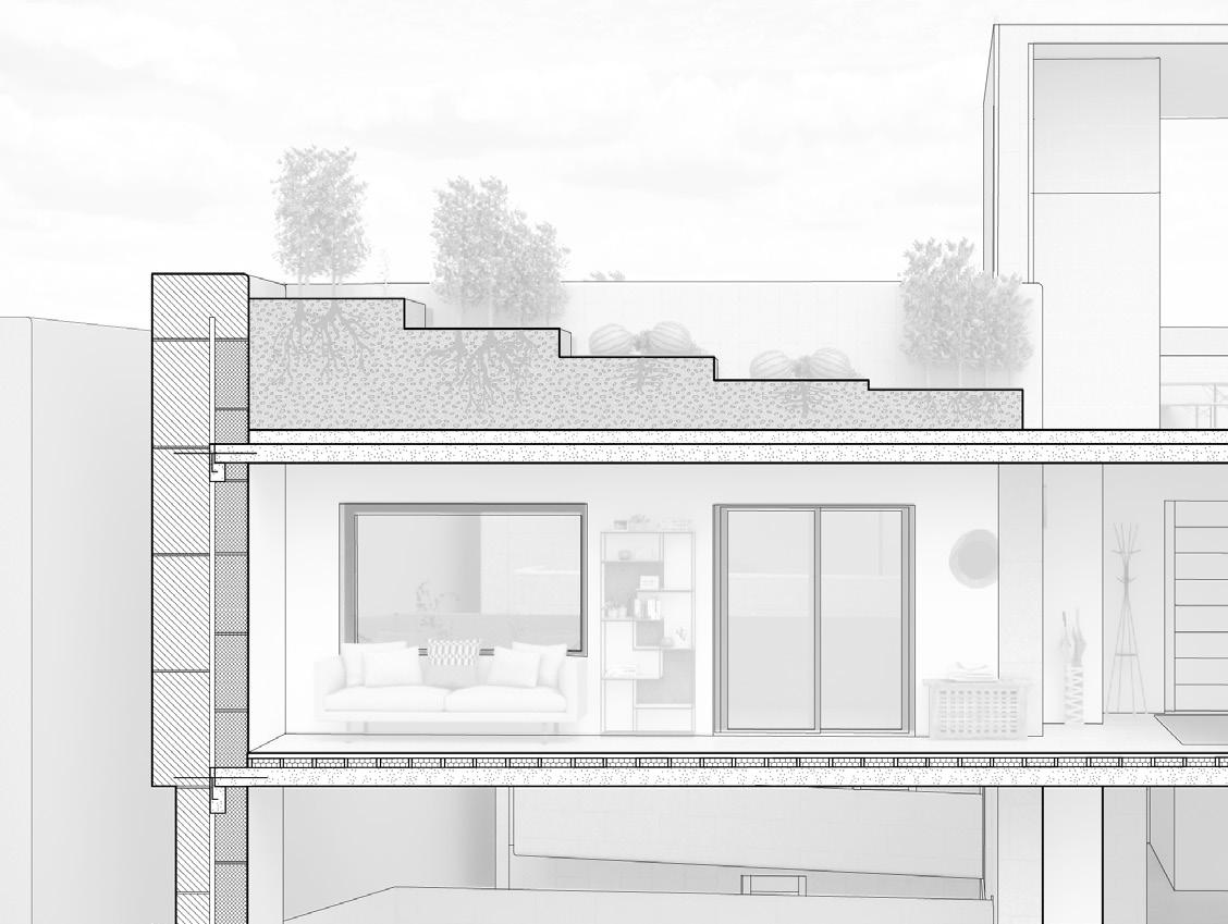


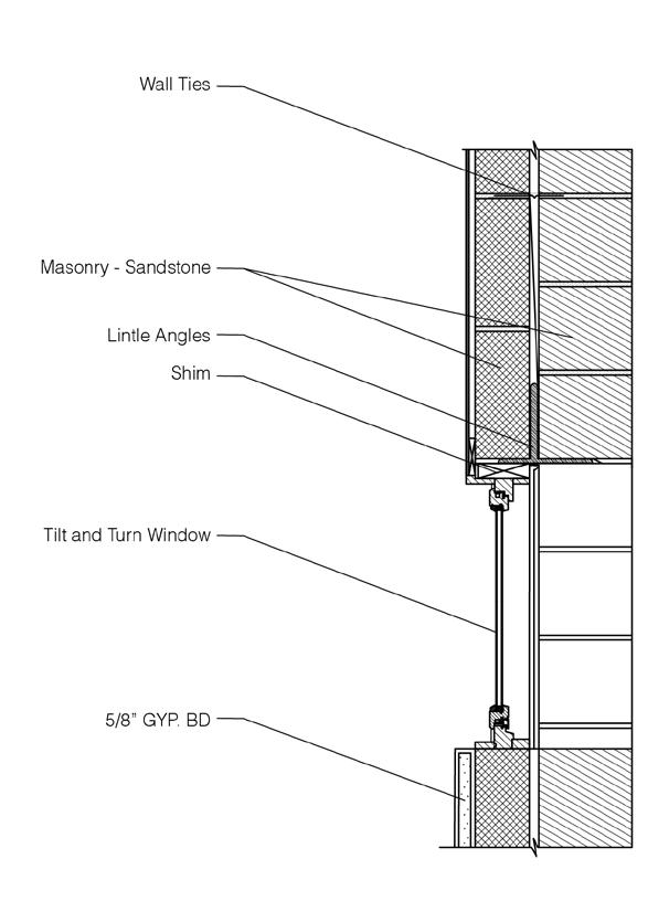

TOP LEFT: North-facing section of the complex with some detailing.
TOP RIGHT: Window detail diagram.
BOTTOM: Floor to wall detail diagram with wood types.
LEFT TOP: Wall detail diagram, and calcualtion of its thermal transmittance.
LEFT BOTTOM: North-facing section of the complex with some detailing.



Eagle’s Nest Lookout
Year 2022-2023
Location Manitou Mountain Trail, Great Madawaska
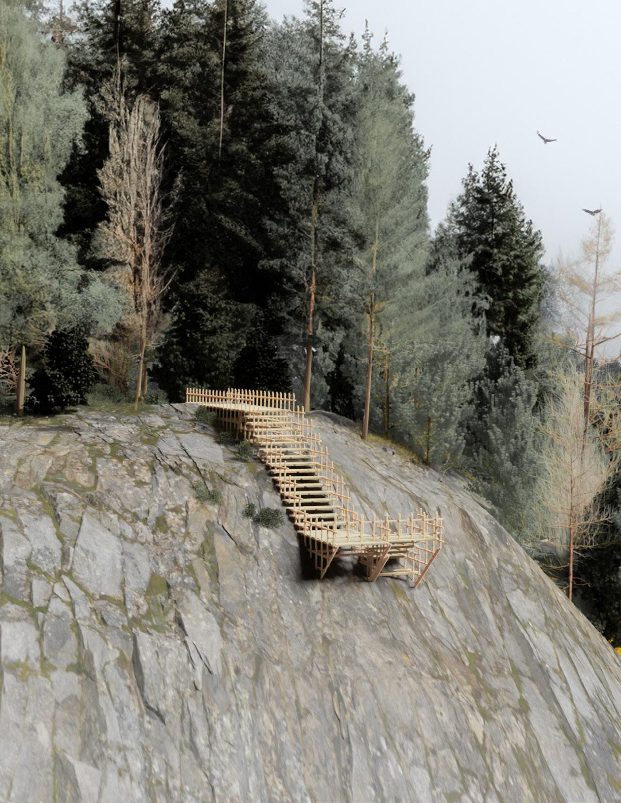
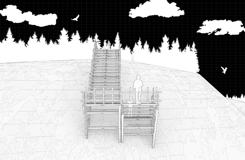
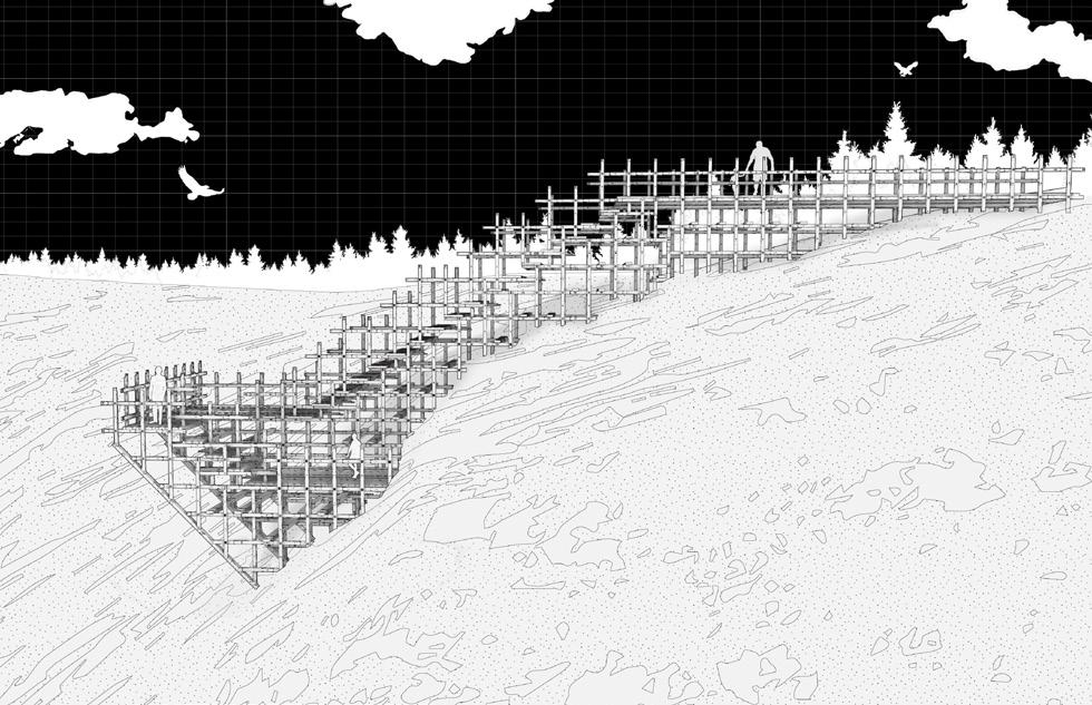
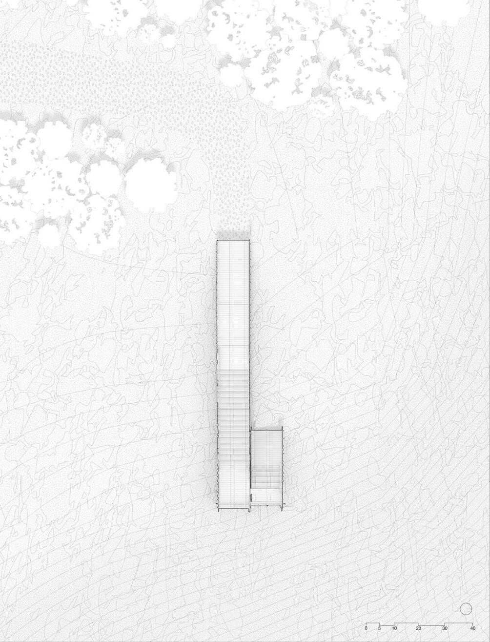
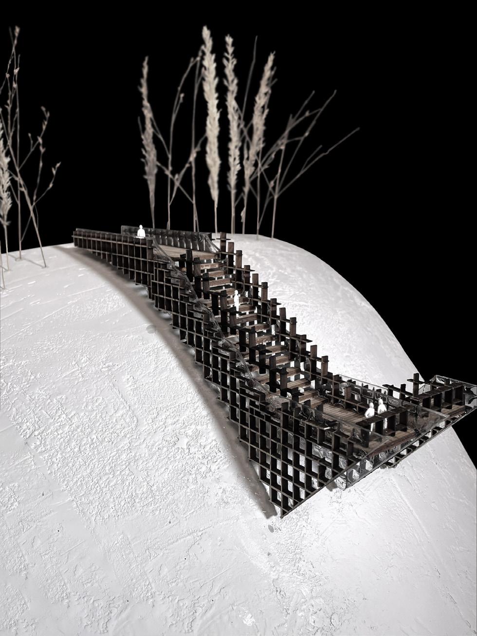
Eagle’s Nest Lookout, at the Manitou Mountain Trail is found in the township of Greater Madawaska. This work was comprised of two stages of development - the creation of a tectonic joint system, and the creation of a structure made of those joints.
Through a complex interlocking of 3 types of joints, the lookout acts as a staircase down the cliff side, bringing the visitor up close to the rocky terrain. The lookout brings them off the face of the cliff, allowing them to receive a near panoramic view of the lookout.
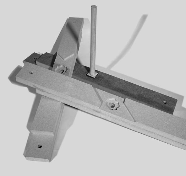
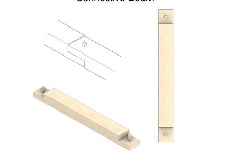
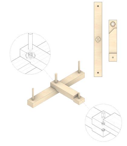
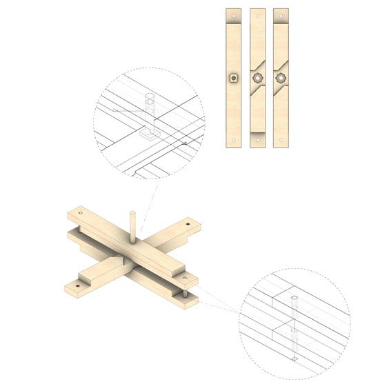
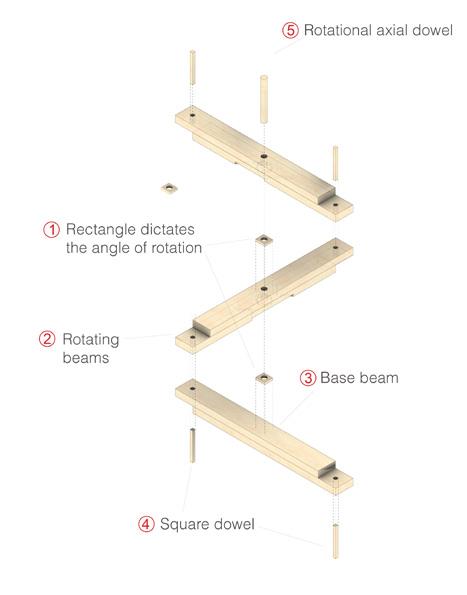
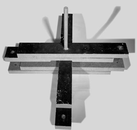
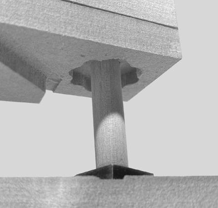
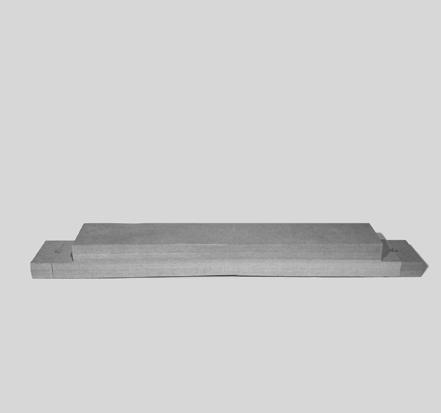
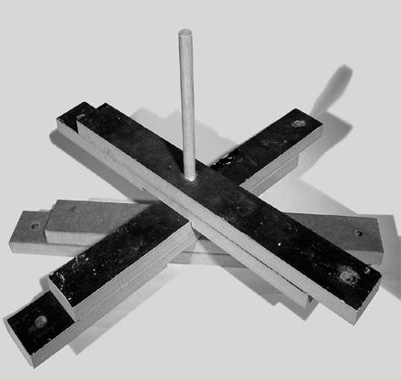
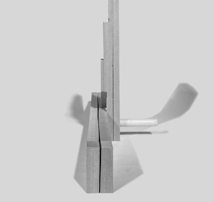
The three joints used in the project are joined to form a tectonic structural staircase. Two of the joints are rotational locking joints; one is a triple cross beam joint, and the other is a half beam joint. The third joint is a simple connective beam, allowing the three joints to connect neatly together.
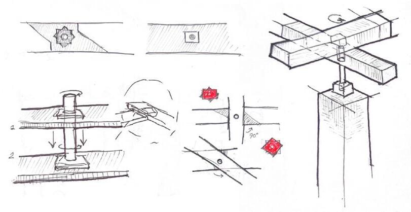
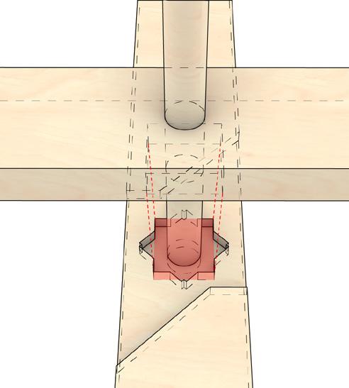
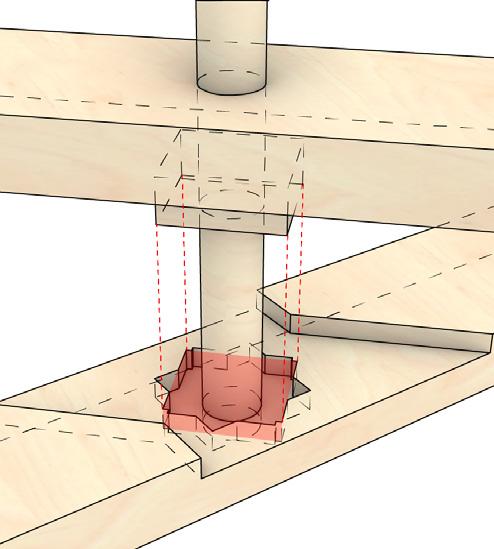
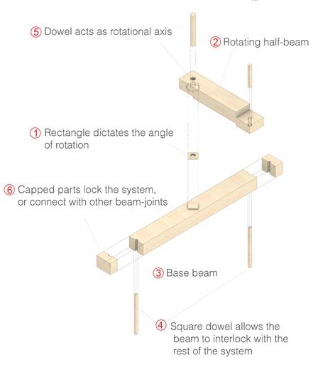
Tectonic System: There are three types timber tectonic connective members within the system; the connective beam, the half-beam joint, and the triple-cross beam joint. The common characteristic between the half-beam joint and the triple-cross beam joint is that the angle at which the joint is set at can be adjusted, due to the uniquely designed connective point. Held together by a rotational dowel, the beams can be adjusted and set into each either; at a 45, 90, or 180 degree angle. The simplicity of its setup allows for greater accessibility within the construction process while simultaneously allowing for a range of possible structures.

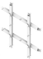
Supports Consists of:

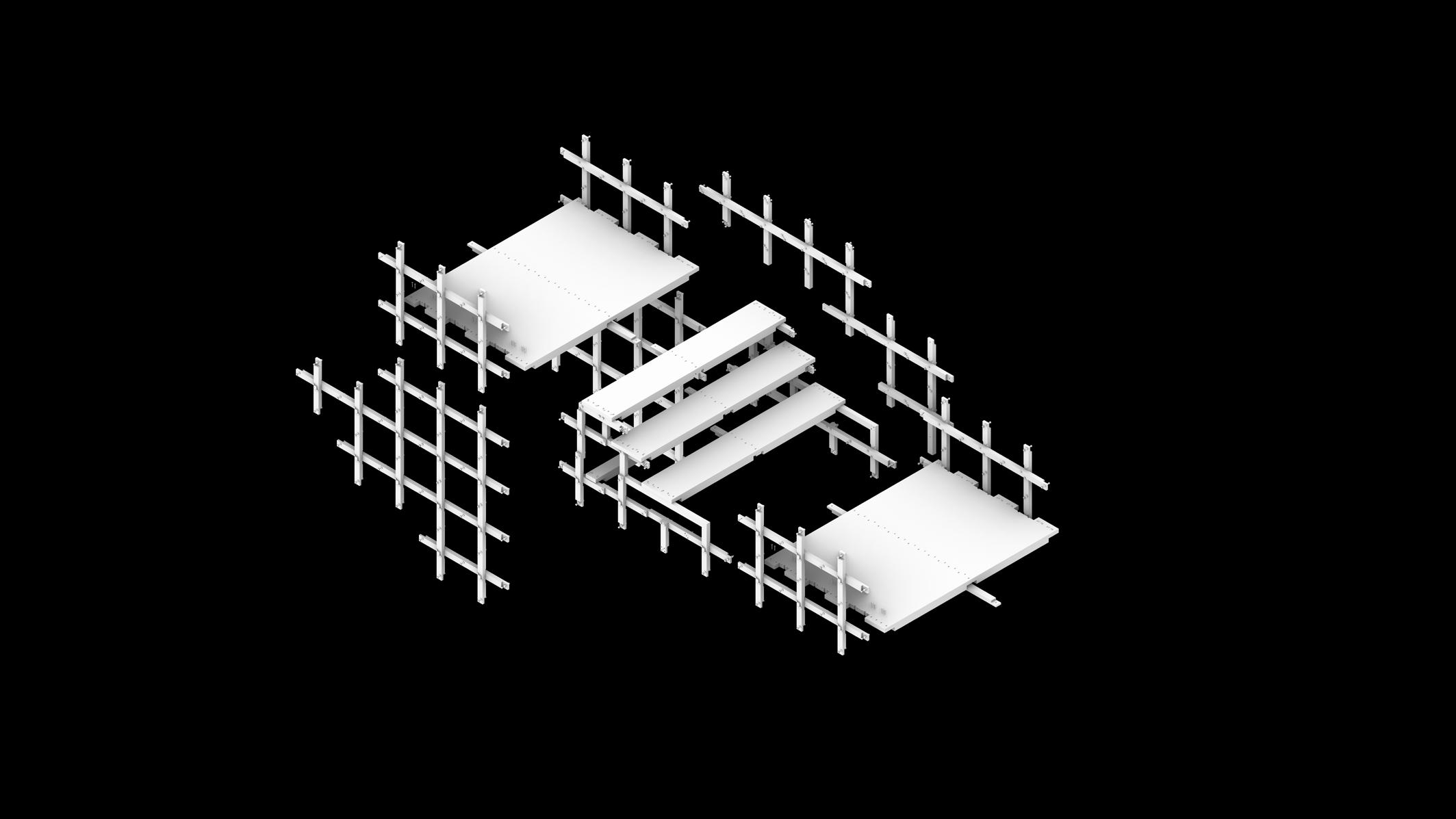
Steps Consists of:
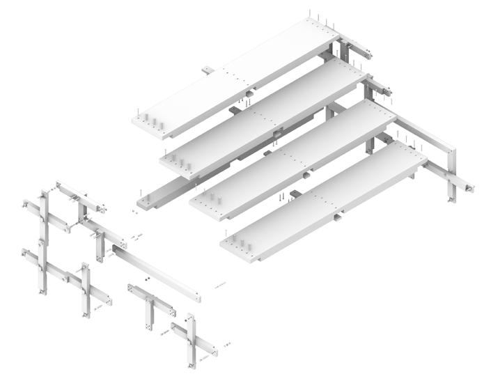
ABOVE: Chunk of the Eagle’s Nest Lookout Stair Tectonic system, highlighting each individual part and how it all comes together - from its individual members to the four main sections.

Consists of:
Beam Joint (double) (With end connection cut off to sit on Board Walk)

Board Walk
Consists of: Support Beam Triple-Cross Beam Joint (double)
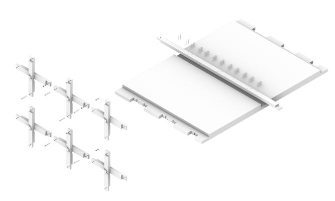
StructuralAssembly: The individual members all come together connected with bolts and wooden dowels to form the larger tectonic system. The Triple-cross beam has one member taken out in this specific stair system. The system is comprised of four main parts - the supports, the steps, the railing, and the boardwalk.
The descending form fo the lookout is shaped specifically to the Eagle’s Nest cliff face. As the individual members of this structure, the structure was scaled to simultaneously fit the cliff face, allow for ease of use by visitors, and support structural loads. The Triple-Cross Beam joints used in the supports form a grid-like structure, allowing it to act as railing, provide structure, and as a foundational point into the cliff face. In this assembly, tieback foundations were used.

Tailored Terrain: Data-driven Botanical Integration
Year 2023
Firm: gh3*
Design Research Internship Program
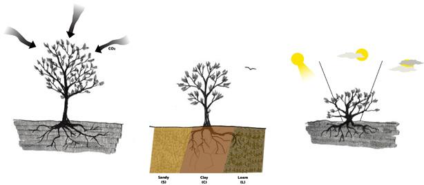
This work was focused on how a site-condition specific approach can influence the plant species integrated within the project. Recognizing the health and environmental benefits of urban planting, the work aimed to reduce urban heat and GHGs, fostering a sustainable city. A given site and its conditions can be studied to sustainably pick plants that would form a mutually beneficial relationship with its context.
A comprehensive botanical knowledge base was established, featuring over 300 plant species native to Ontario. Each species was cataloged with 21 detailed characteristics, including hardiness zones, soil type preferences, moisture requirements, sun exposure, and carbon sequestration values. This database served as a tool for streamlining and optimizing plant selection in landscape design by allowing species to be filtered and matched to specific site conditions.
The new plant selection process was tested on the Pier 8 Greenway project, where it was used to develop sustainable plant groupings and potential landscape plans. Additionally, this process was integrated into the studio’s existing workflows, facilitating a more efficient site analysis based on sun exposure. The system enabled automatic placement of plant clumpings within a digital model of the site, enhancing the overall design process by ensuring plants were positioned for optimal growth and sustainability.
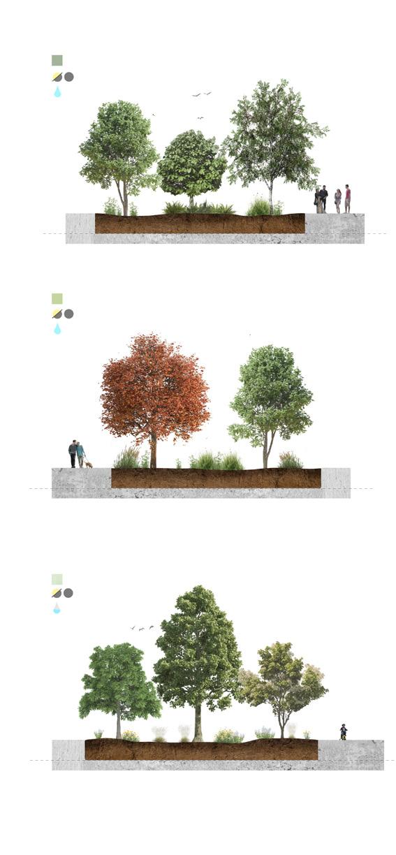
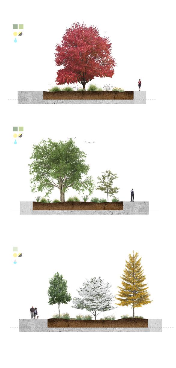
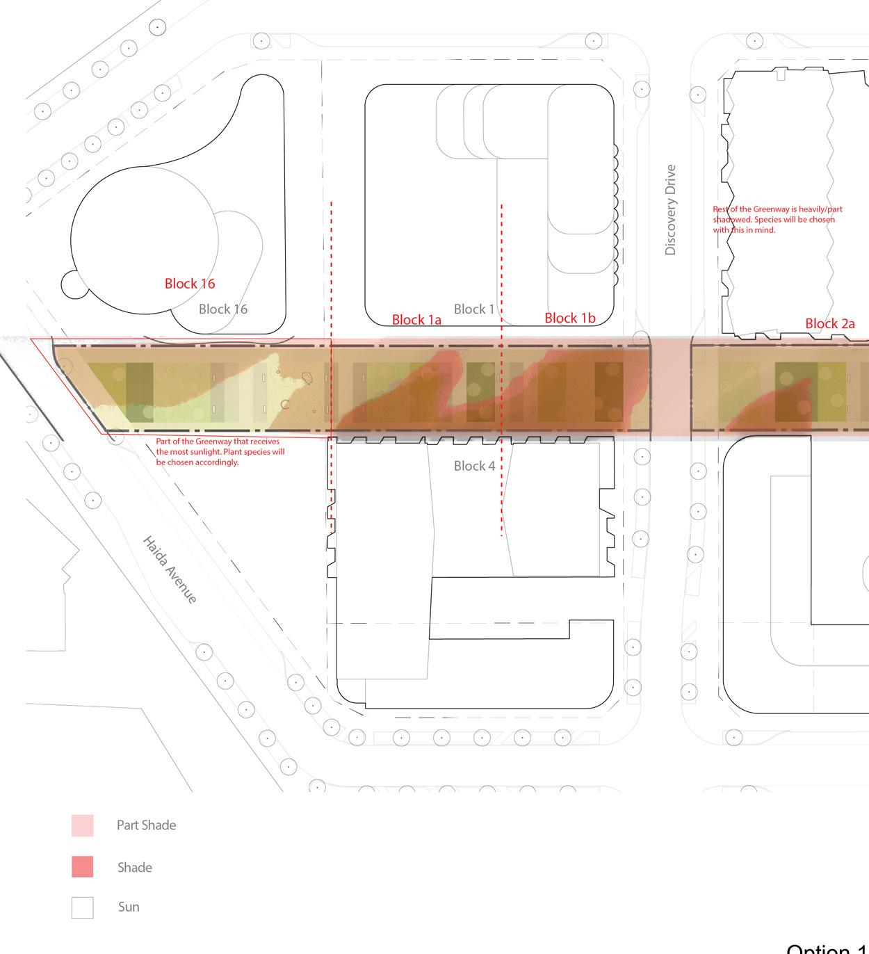
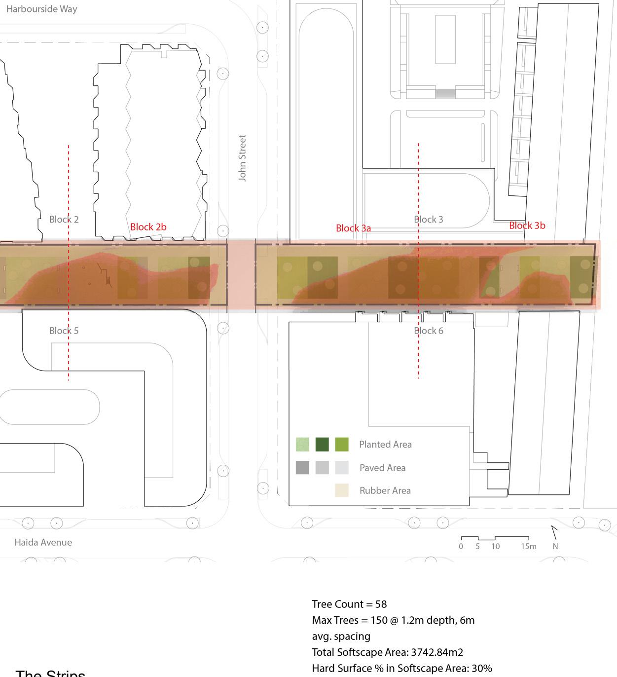
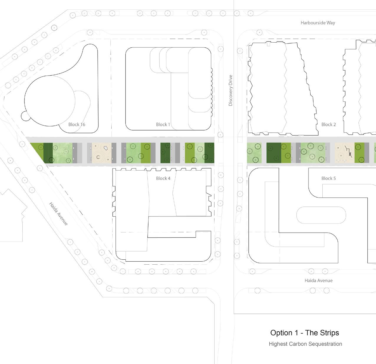
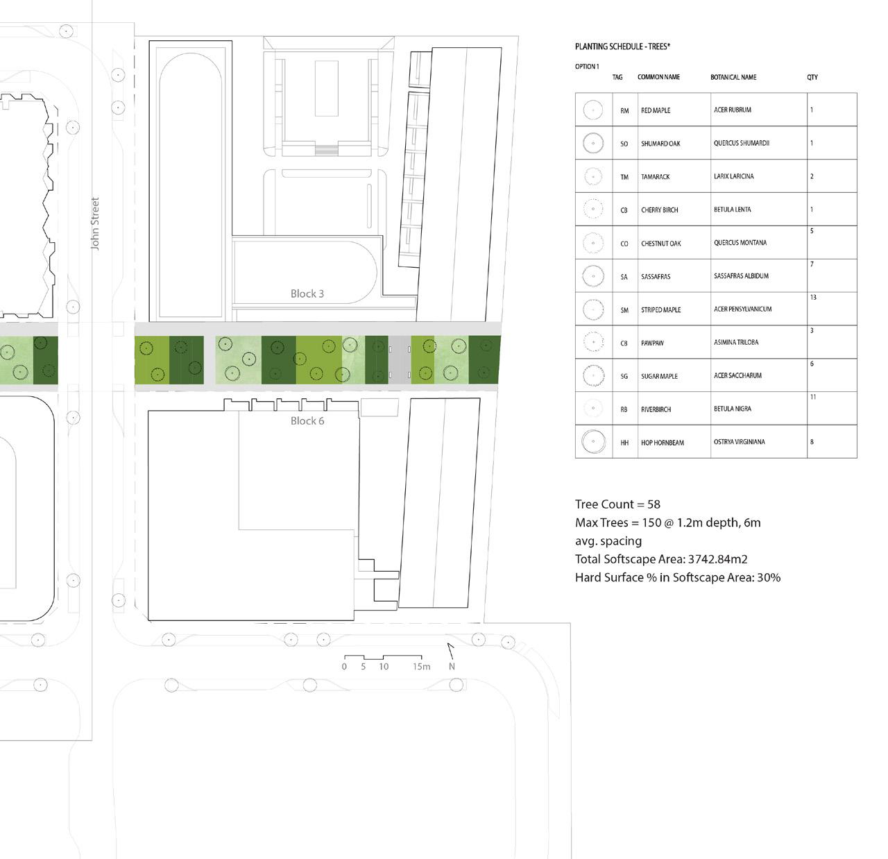
ABOVE: To test the database and its visualiation, a landscape plan and plant groupings were developed for the Pier 8 Greenway project, which is currently in progress. It was tested against one of the previous iterations of the landscape, named “The Strips”. The first step was to evaluate the site’s conditions, assign potential soil type and moisture amount (controlled by irrigation), then use the visualization and database to create plant groupings.
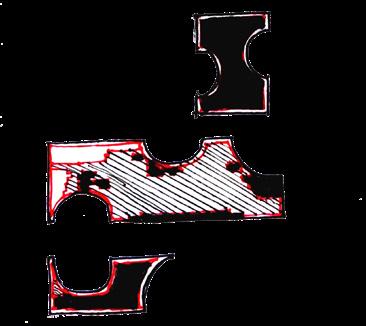
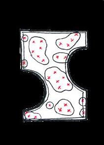
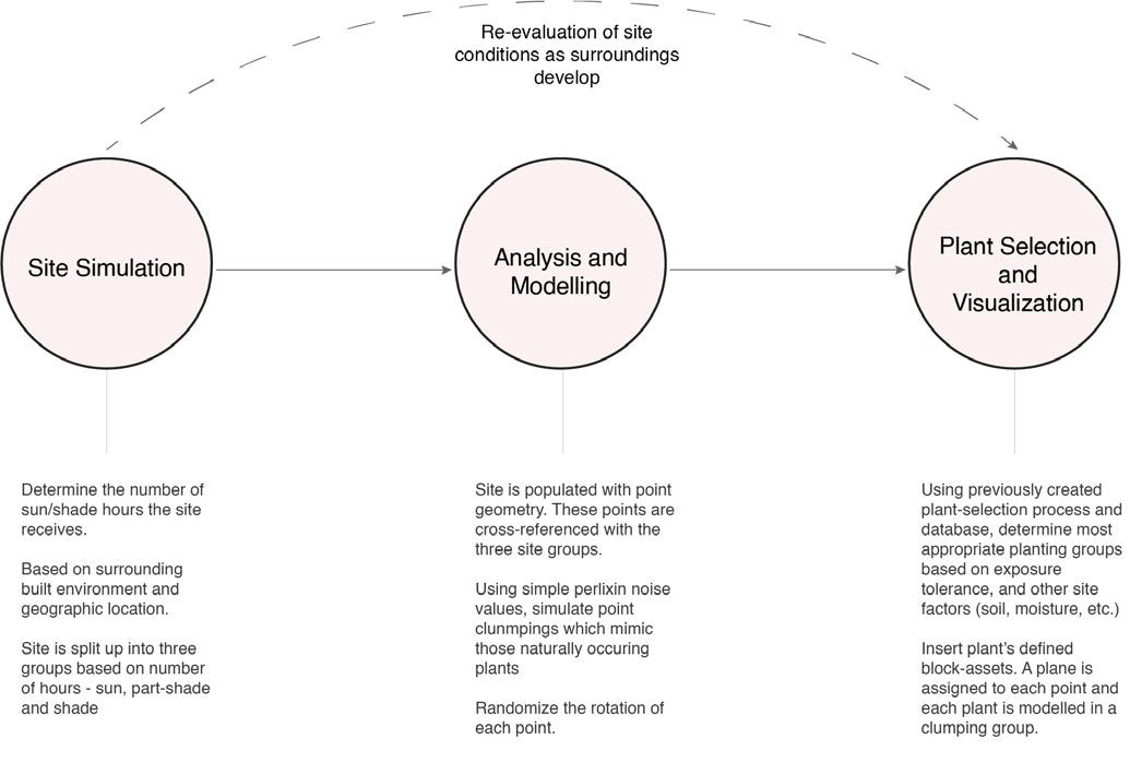

ABOVE: A further exploration into how the planting database could be further integrated into the firm’s work flow, through automation and scripting. Flowchart and diagrams explaining the Grasshopper Script developed for this project. It was tested on a massing model provided by the firm.
RIGHT: 3D sunpath diagram of the site, and the three levels of exposure on site - sun, part-shade, and shade.

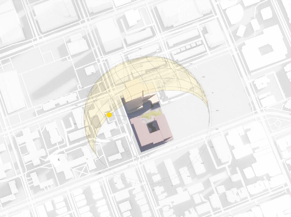
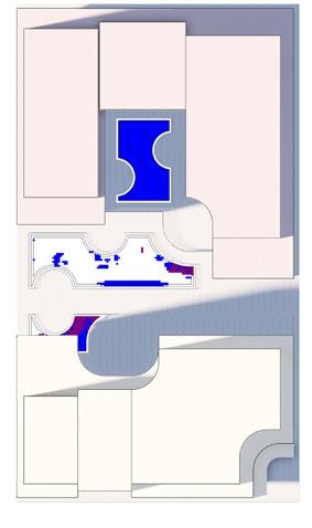

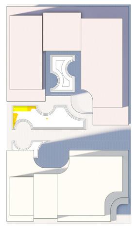

Parametric Design: To further integrate the database into the firm’s workflow, the information was integrated into an automated-planting workflow. Using real weather data, I analyzed sun exposure and divided a site into three sun exposure levels. Through the database, the most suitable plantings were selected for the site. A plant clumping script scattered plants based on exposure and modelled them, further streamlining the process from the Pier 8 study.


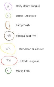


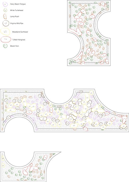

TOP LEFT: A planting collage displaying the types of plants selected for the site and their exposure tolerances. To the right, a handdrawn planting plan of the site.
BOTTOM LEFT: A rendering of the planting site and its selected plantings . The placements of the plantings was determined using the planting script created.
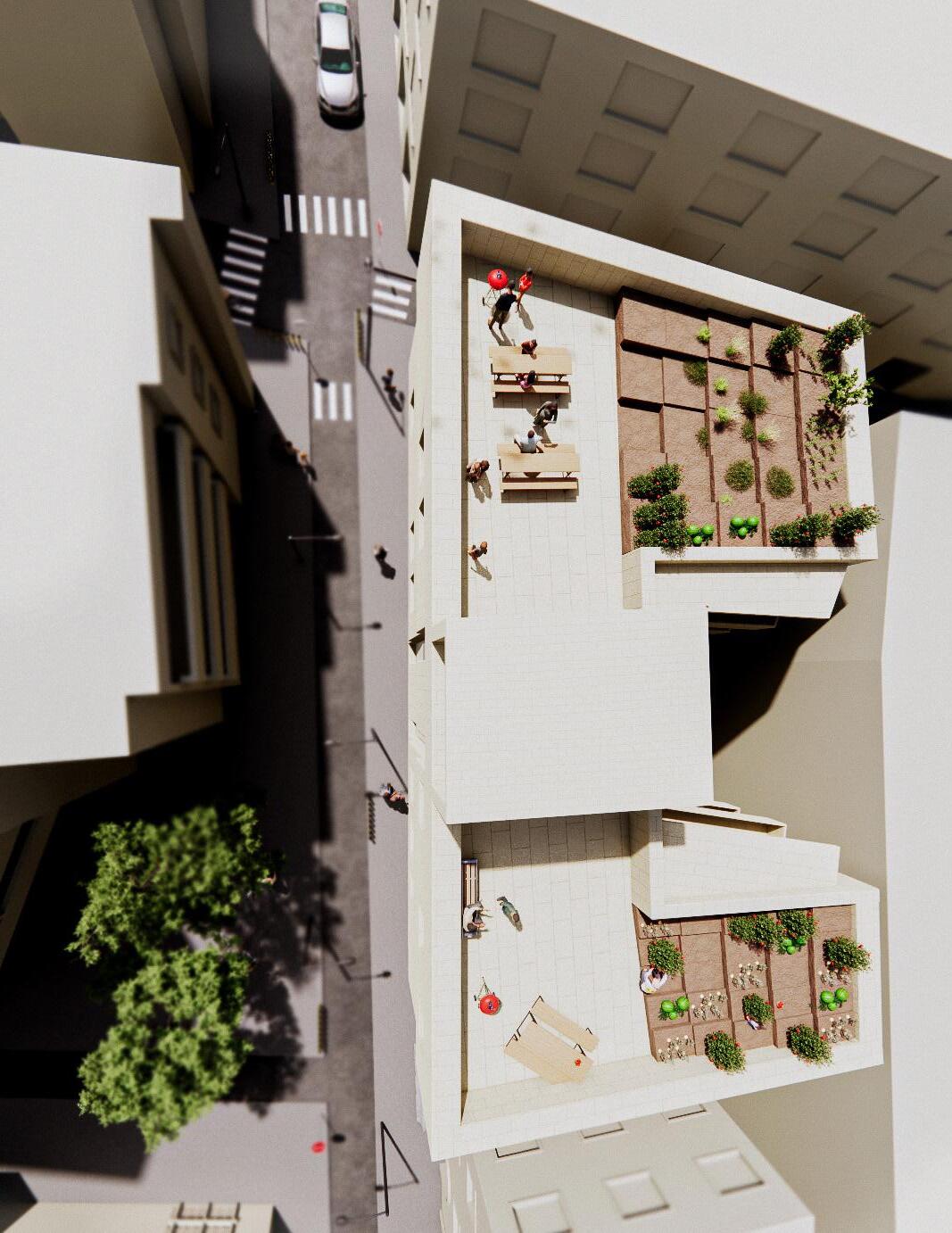
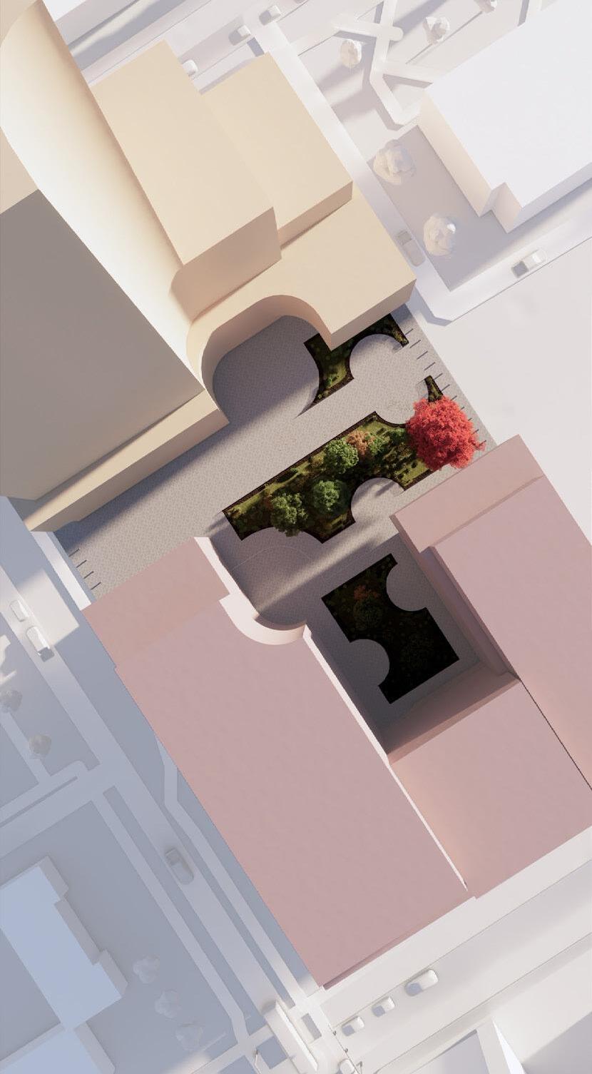
RIGHT: A rendering of the building on site within it’s urban context.
Residential Representation
Year 2021-2023
Company Urban Simplicity, Ottawa
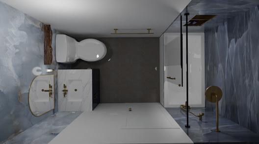
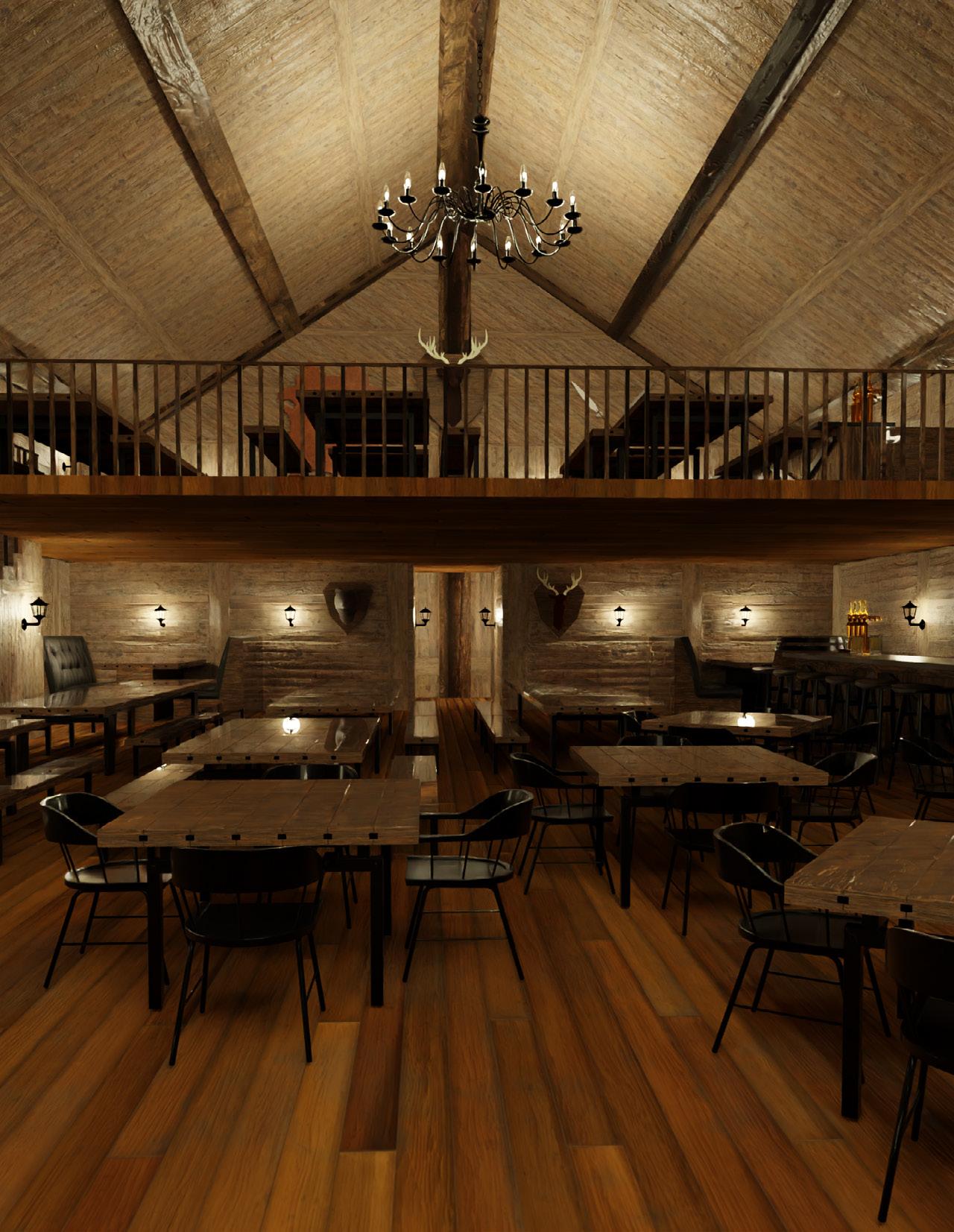
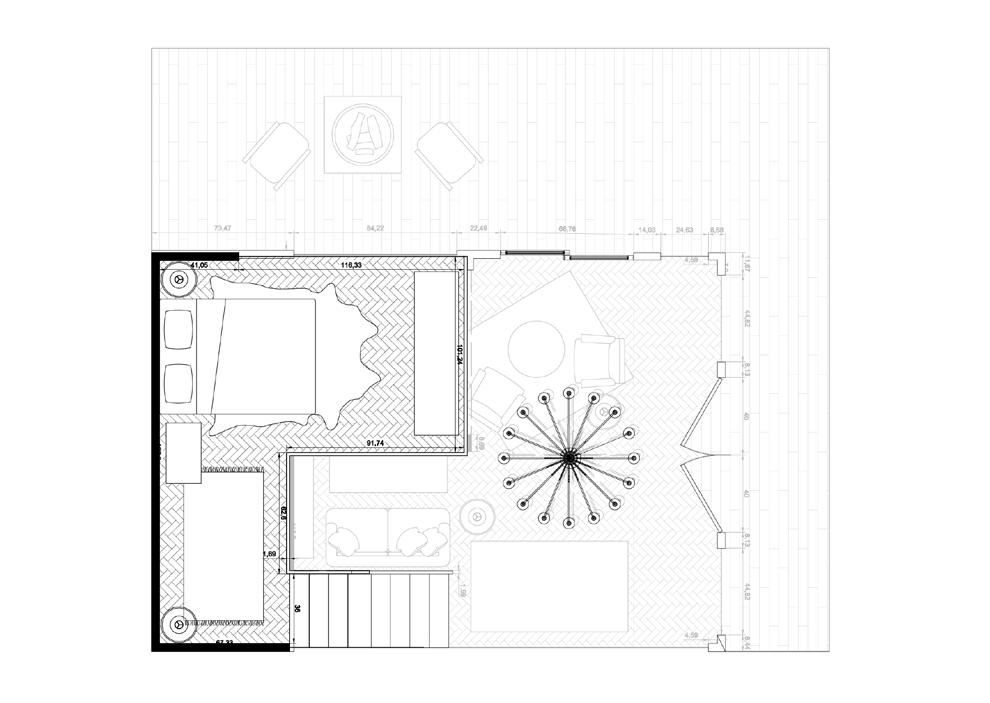
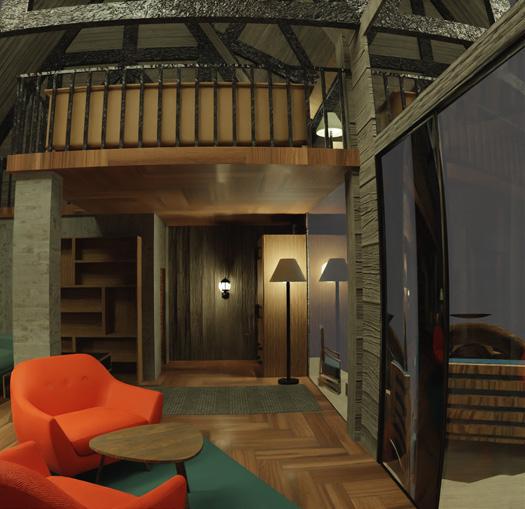
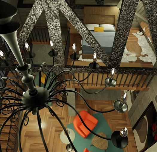
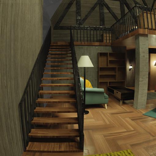
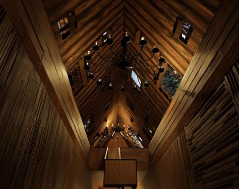
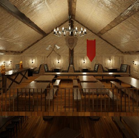
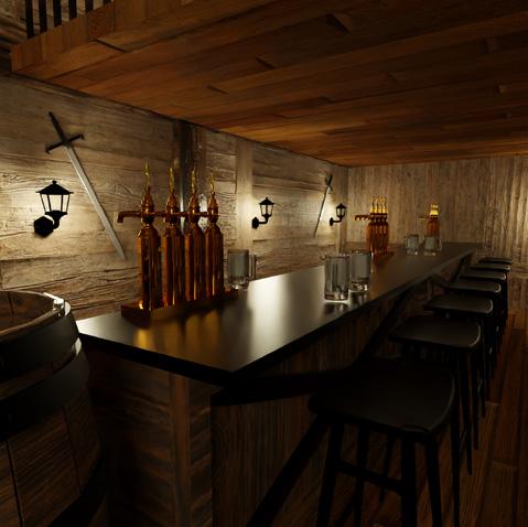
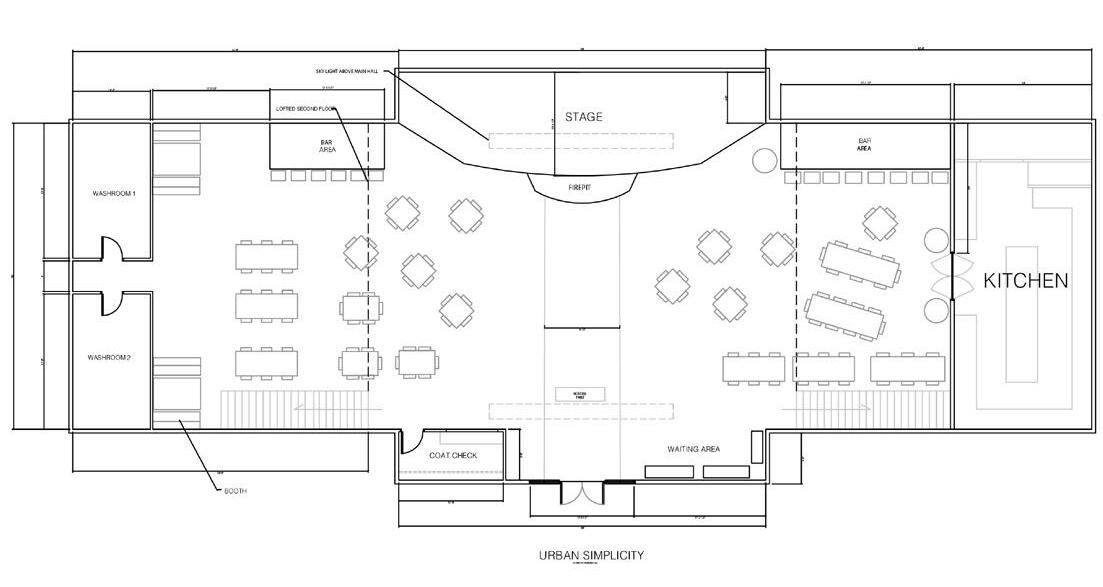
Collection of drawings and renders created for a job as a subcontracting architectural drafter at Urban Simplicity, an Interior design firm based in Ottawa. Drawings and Renders include residential renovation works, and potential imaginative projects.
Each render and drawing was created to follow specific guidelines based on the clients’ preferences. They were then presented to the client as part of the initial stages of the design proposal.
At the firm, I acted as a CAD and Render Drafter. My responsibilities were to re-interpret rough, conceptual sketches into floor plans, elevations, and renders for client presentations. The following designs are of my own creation and have received approval from my supervisor.
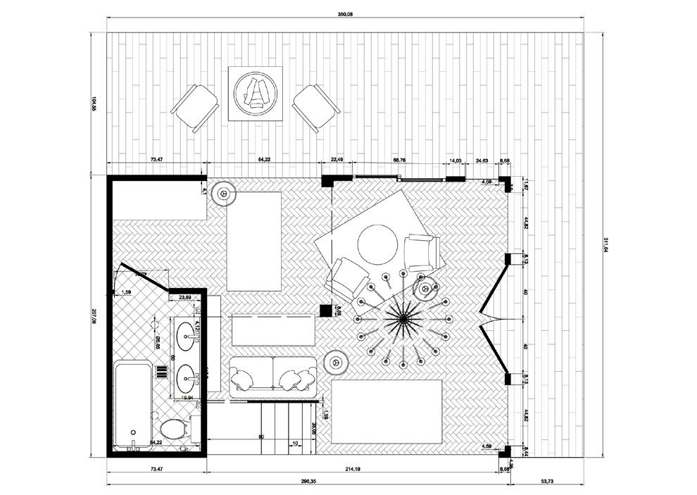

TAXIDERMY ROOM
FIRST FLOOR
BIRD-WATCHING BALCONY
TROPHY ROOM
STORAGE ROOM
ACCESSIBLE WASHROOM
ENTRANCE/FOYER
BIRD-WATCHING FLOOR
SECOND FLOOR
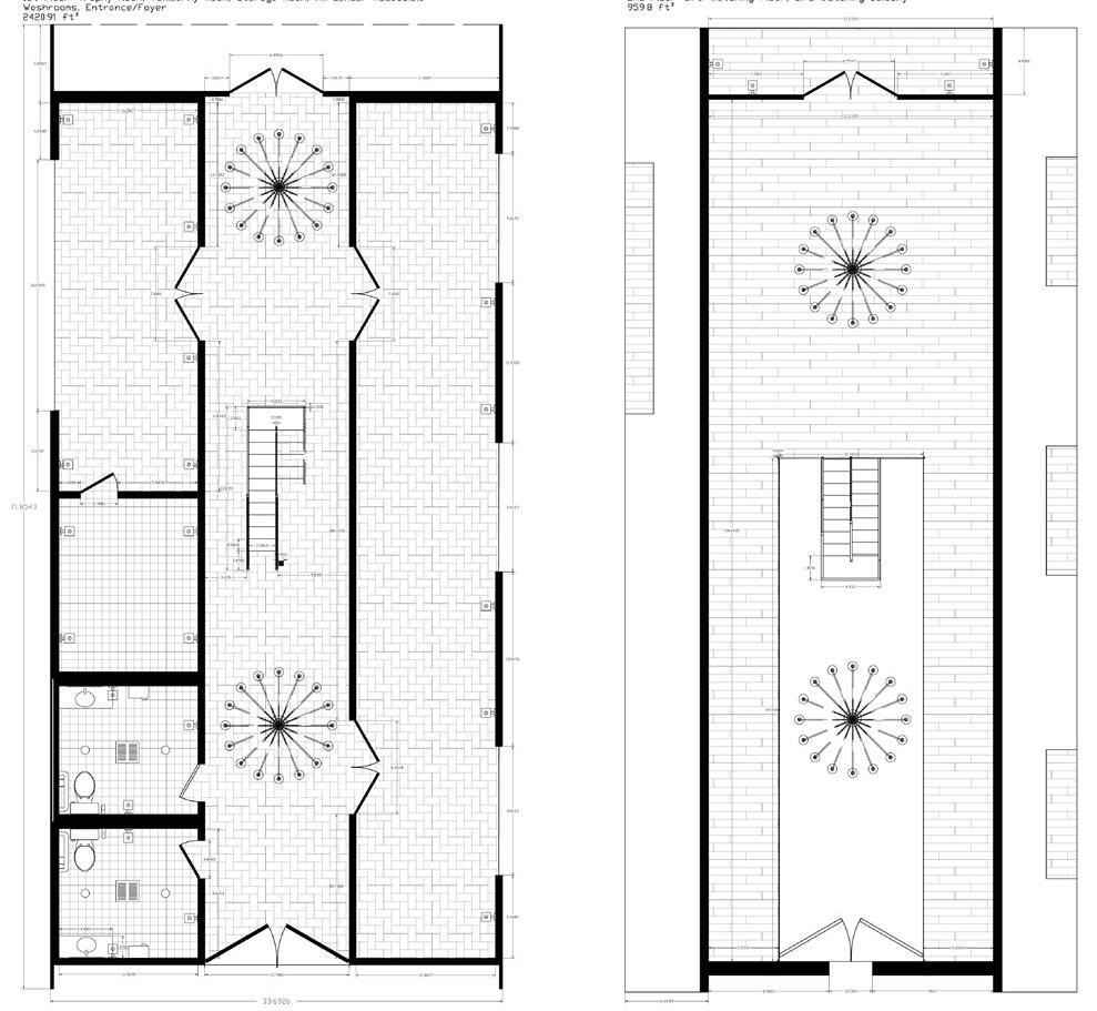
ACCESSIBLE WASHROOM

GROUND FLOOR

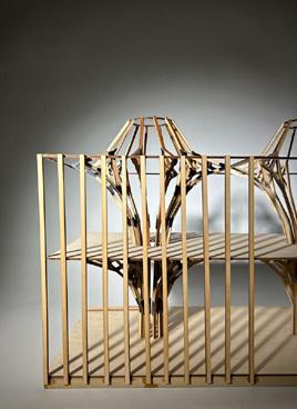
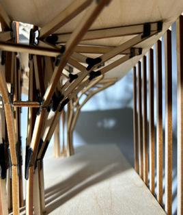
Precedent: Long-Fu Life Experience Center
Year 2022
Team Selina Almadanat, Meera Thomas
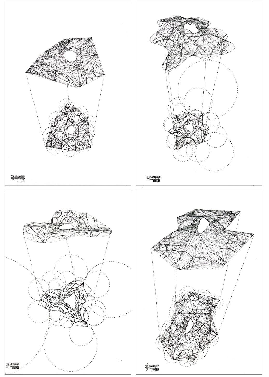
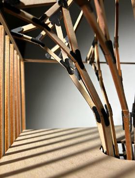
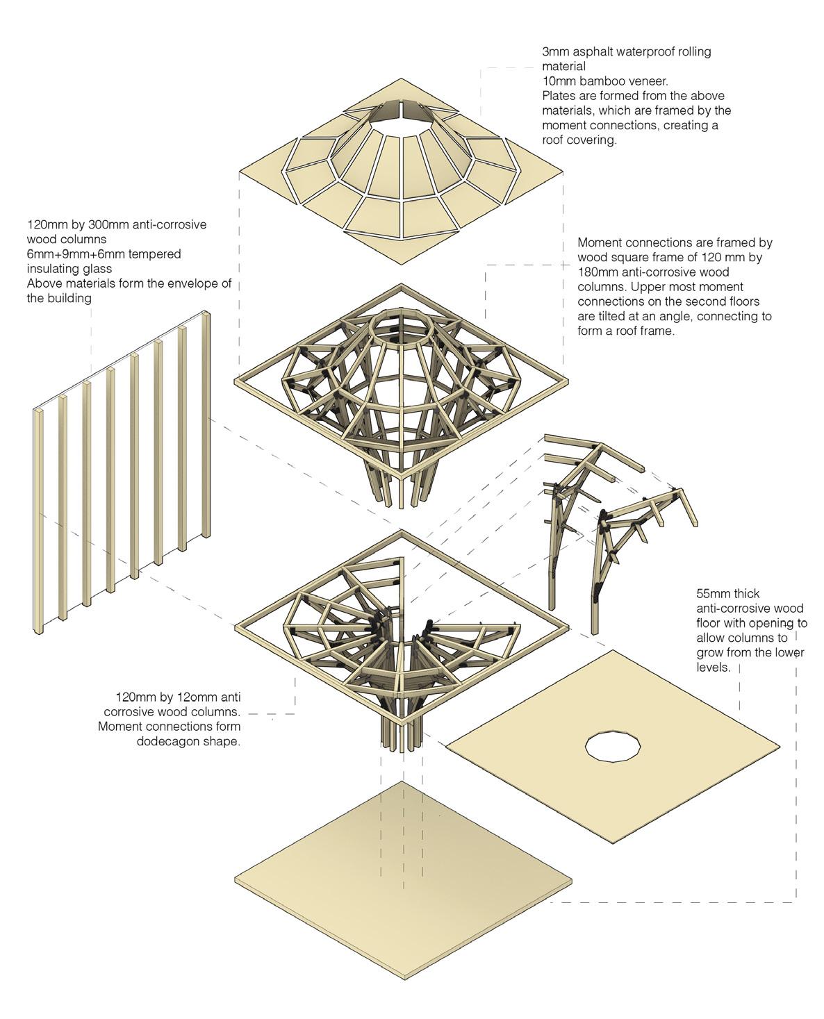
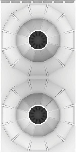
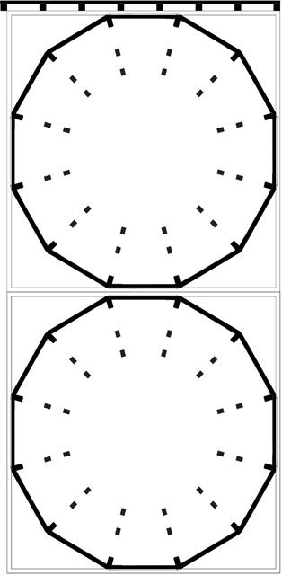
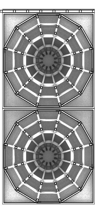
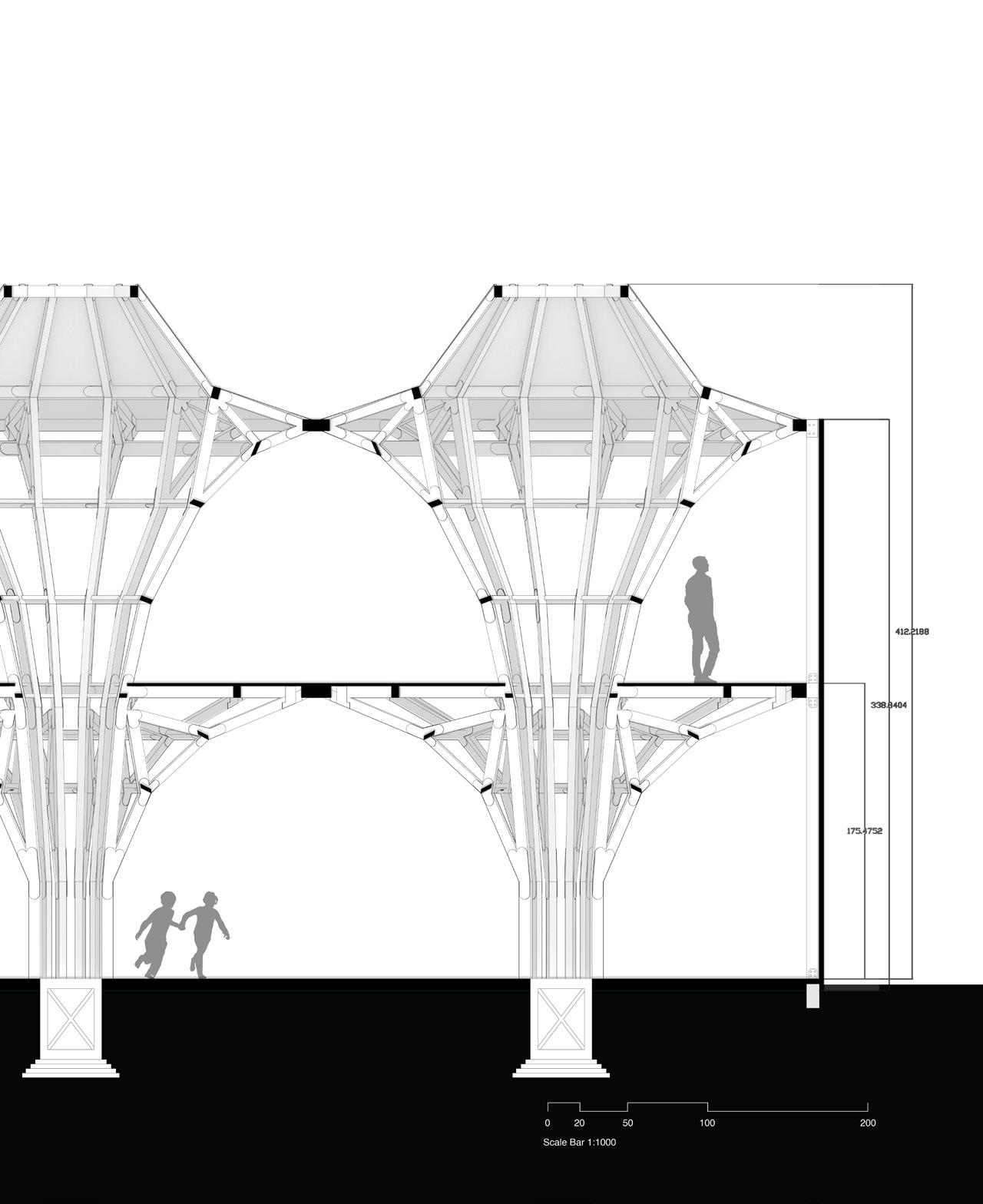
This study of the Long-Fu Life Experience Center by LUO Studios in Puyang, China, examined the building’s form and timber structure. The key elements are tree-like timber columns that span both floors, divided into five parts and joined by metal plates and bolts. Arranged in a dodecagon and connected through moment joints, these columns provide both structural support and aesthetic complexity.
The project explored how mass timber can beautifully merge structure and design. Models and drawings were created using Grasshopper and Rhino to highlight the potential of timber in architecture.
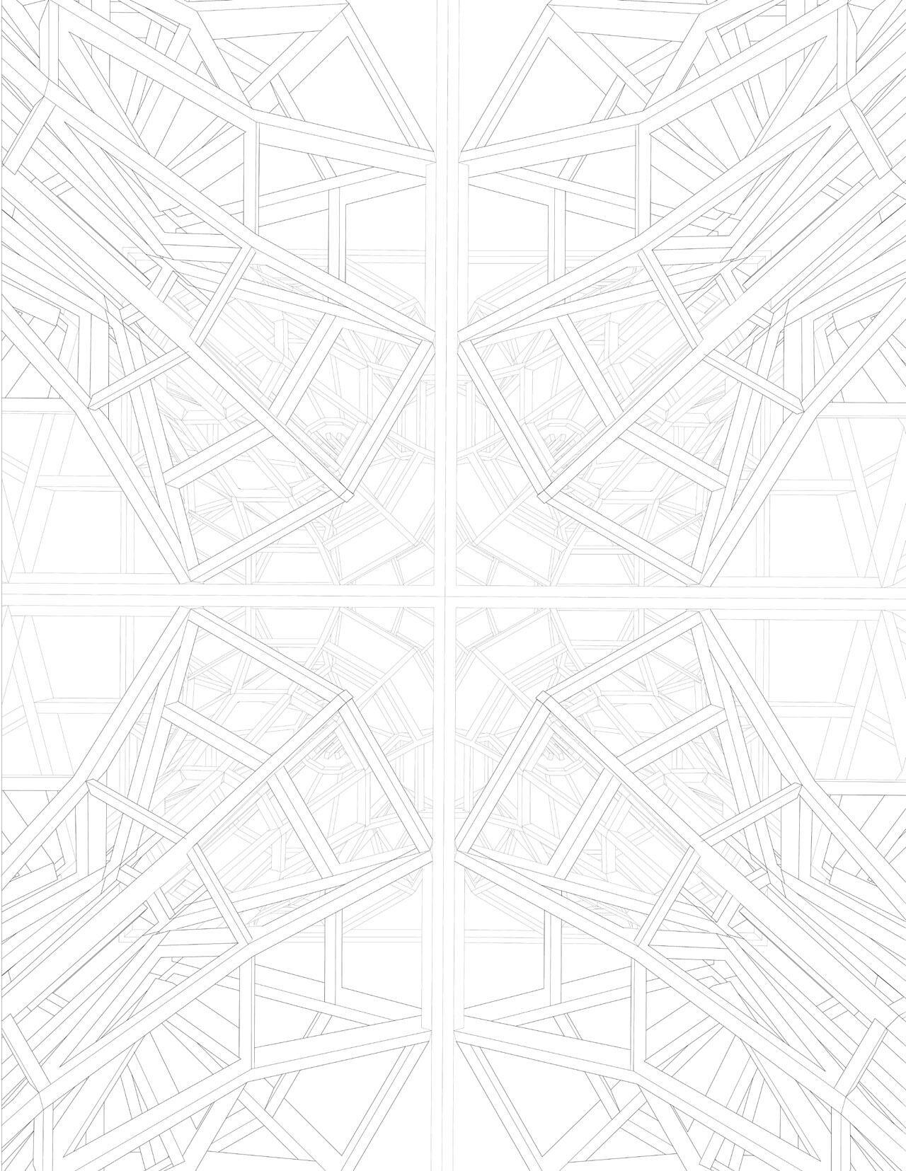
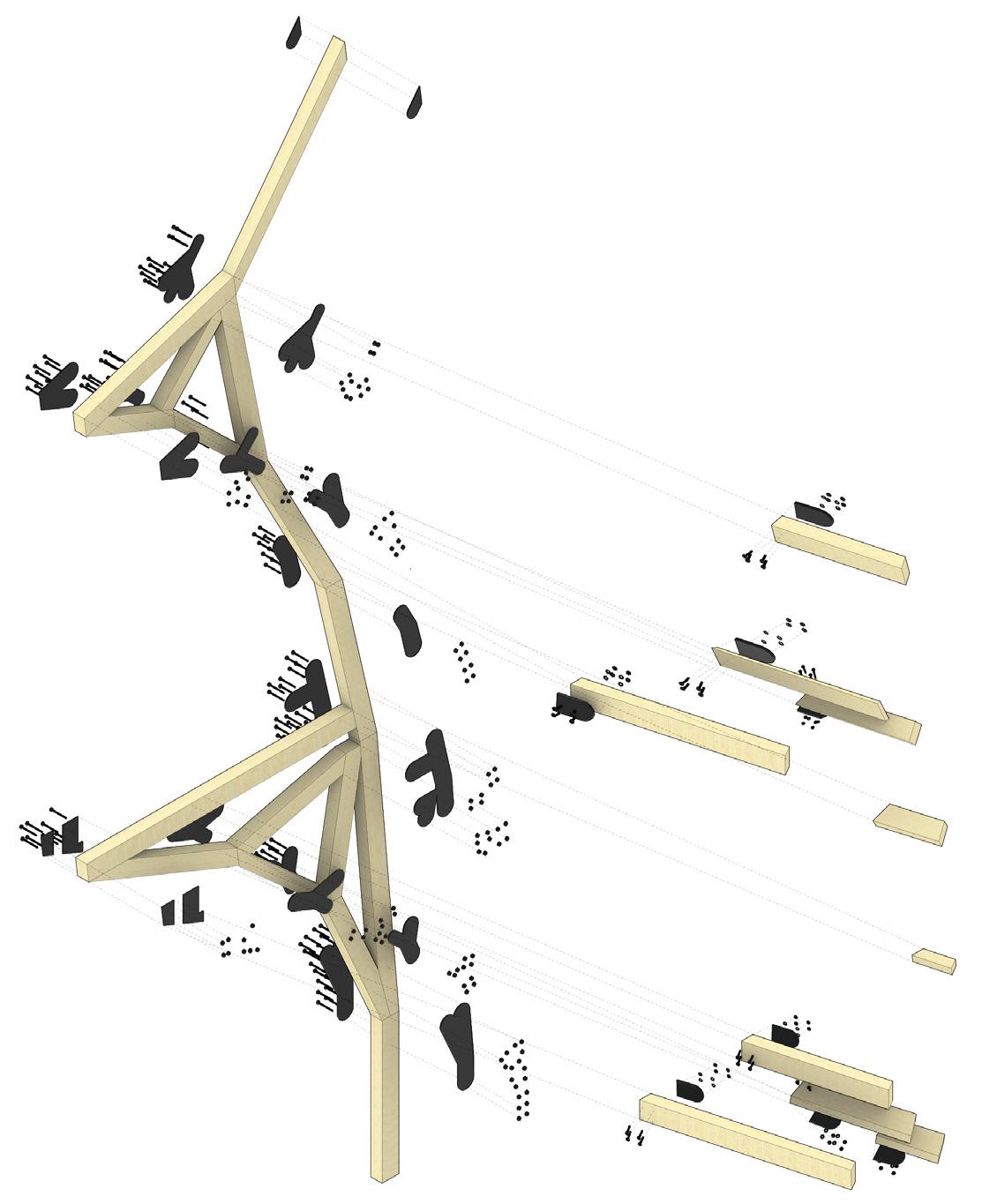
LEFT: Branch exploded axonometric showing assembly. Using section drawings and plans, a portion of the treelike structure was mathematically analyzed and replicated in Grasshopper. The structure features vertical timber beams supporting an upper level, with additional beams at each vertex for connections to the rest of the design.
RIGHT: Full structural and cladding exploded axonometric



Fabrication Project: Aeolian Soundscape
Design Team John Nguyen and Nicholas Hoban Fabrication Team Selina Almadanat, Nermine Hassanin, Cameron Manore, Renee Powell-Hines, Meera Thomas, Liam Cassano, Elham Khataei, Zhenxiao Yang, Zachary Mollica, Paul Kozak, Rahul Sejihpaul
Photographer 6ix Films Year 2023
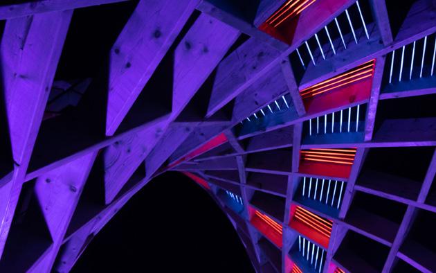
This project, created for the Lumière: The Art of Light Festival at Ontario Place, uses the site’s windy environment to reinterpret the aeolian harp through a reciprocal frame structure. It features lamella segments arranged in a grid, enabling long, free-form spans from short members.
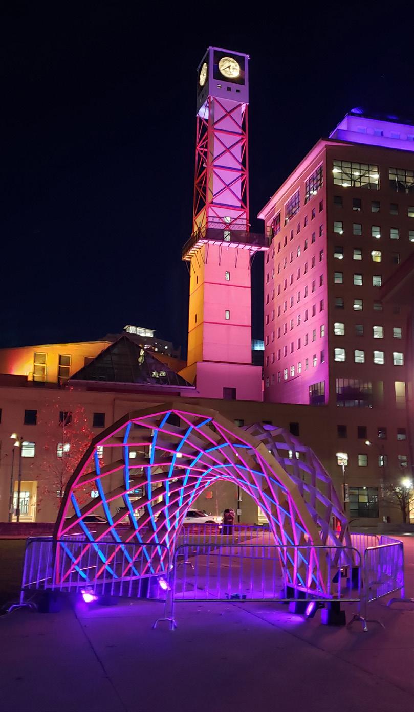
Technical expertise in geometrical fabrication is displayed and auditory senses are simulated by harnessing the wind and aeolian harp elements. Fluorescent nylon strings, along with Black LED lighting accentuate the night time experience while remaining unique in the daytime.
The structure was later re-erected at the Living Arts Center, as a part of the Mississauga Winter Lights Festival.
I was a member of the fabrication and construction team, in which I utilized a KUKA Robot arm to 6-axis mill each member, and used traditional wood-tension construction methods to help assemble the structure on site.
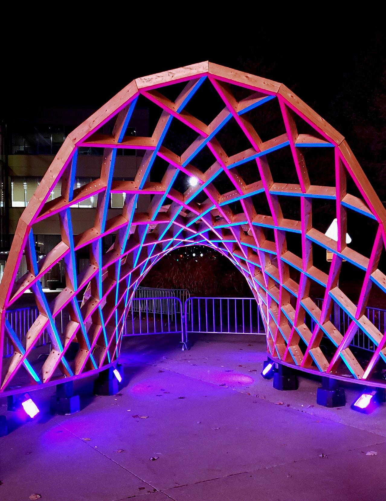

FABRICATION: This project, one of Canada’s first double-arch reciprocal frame structures, was designed entirely using a Grasshopper algorithm to optimize beam angles and lengths. A KUKA Robot Arm milled each beam with precision, and they were coated with a polyurethane finish for weather resistance. For the Mississauga Winter Lights Festival, the beams’ thinner sides were painted with UV red and blue to highlight a woven pattern. Pre-assembled into cells, the beams were then easily assembled on-site, minimizing errors and reducing installation time.

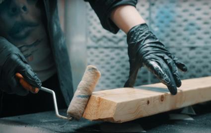

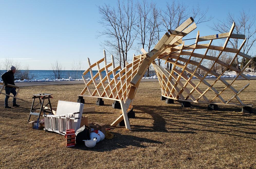
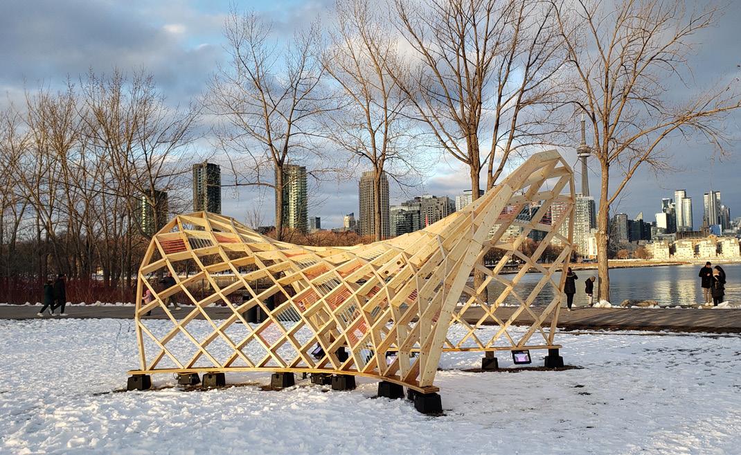

Photos of the final structure at Ontario Place. This double-arch reciprocal frame structure was designed using a Grasshopper algorithm, optimizing the beam angles and lengths for precision. Each beam was milled by a KUKA Robot Arm and coated with polyurethane for weather protection.
RIGHT: For the Mississauga Winter Lights Festival, the beams were painted with UV red and blue to enhance a woven effect. To streamline assembly and minimize errors, the beams were pre-assembled into cells before being installed on-site, significantly reducing installation time.
Thank you for reading!
LinkedIn: Selina Al Madanat
Email: selina.almadanat@gmail.com
Tel: +1 (437) 882 4932 Toronto, ON, M4Y0E9
