12 minute read
Causes of Punch Tip Wear and How to Avoid Them

from IPI Winter 2020
by Senglobal

Punch tip wear is a commonly overlooked aspect of many tooling inspection procedures. Tip wear is typical and can be influenced by many different sources, including poor tablet and tool design, granulation characteristics, improper steel selection for the application, and improper press setup. It is quite typical for inspection technicians to pay attention to the punch cup face. Wear to the cup face is generally not responsible for typical tablet defects such as capping, lamination, and flashing. These tablet defects are more related to punch tip land and outer edge wear.
Punch tip edge wear can result from a number of conditions and may cause myriad problems including raised edges on the final compressed tablet, commonly referred to as “flashing” (Figure 1). Tablet flashing, in turn, can cause many other issues after the compression event. When tablets are subjected to de-dusting, the flashed edges may break off and cause rough, poorly defined edges. Tablets with flashing and rough edges can be difficult to film coat and can lead to losing particles adhering to the coated tablet surface. To minimise defects and downtime it is important to understand the most frequent causes of punch tip edge wear. The Main Causes for Punch Tip Wear The Design of Tablets Tablet design plays an integral role in the functionality and longevity of the tooling. Once the innovator travels down the path of tablet design, approval, R&D and scale-up, it must then move to production. When tooling is made for production, it is subjected to increased cyclic stresses than in the R&D phase. If the cup is excessively deep or if the concavity of the cup is steep near the edge (as with some compound cups) and creates near vertical surfaces they will be more susceptible to abrasion. This type of cup design is not as robust as a standard cup and will require more land than its counterpart.
Steps to strengthen the edge of the punch cup include reducing the slope of the cup and more importantly, introducing appropriate amount of land into the tablet design. Land unfortunately gets a bad reputation, as many believe additional land will cause soft edges and more difficulty with film coating. Most tool vendors know the value of land and may incorporate it into the design. However, many are forced to use “minimal” land width which is usually only approximately 5% of cup depth. Knowledgeable tablet designers consider that land width should be closer to 10% of cup depth, and occasionally up to 2025% of cup depth, especially for difficultto-compress tablets that require high forces. Any punch tip with no land (razor sharp edge) is considered unwise. Having sufficient land in your tablet design adds strength and wear-resistance, both on the inside of the cup and on the outside of the tip, while creating a more robust tablet and enhancing tablet stability. Formulation/Granulation Characteristics Abrasion due to granulation is a common cause of tip wear and is generally a larger issue in the nutraceutical industry. Nutraceutical products are usually composed of different vitamins and minerals, most of which are quite abrasive, including magnesium, calcium, iron, and zinc. Pharma products with a higher percentage of API typically require higher compression forces which may accelerate tip wear. Besides degrading the finish of the punch cup and wearing of any embossing or score lines, abrasive ingredients also wear away the land and the outer edge of the punch tip. Once any wear occurs to the edge of the punch tip, particles will become trapped in the increased gap between the tip edge and die wall. Then as the punch moves vertically, the abrasive particles are ground in-between the tip and die wall, accelerating the wear to both tool components. Once this occurs there is no turning back … the “snowball effect” takes over and the wear process is accelerated.
Particle size can also affect tip wear. When small particles known as fines are present, they can sift into the gap between the punch tip and die bore. These small particles combined with the cyclic motion of the punches can cause wear on the outer edges of punch tips. While often there is little or no choice as to the components of a formulation, controlling particle size and tip-to-die bore clearance can work together to reduce unnecessary tip wear and extend tool life. Condition of Turret Even though your tooling may be in optimum condition and configuration, problems may quickly arise if they are used in a tablet press with a worn turret. The most common and unrecognised wear point of a turret are the die pockets. Dies are made from harder wear-resistant steel compared to the typical die table and are often installed without the proper installation tools and technique. If the dies are not installed with accurate vertical guidance, keeping them perfectly straight and aligned with the pocket, they will damage the top section of die pocket. Hence this will eventually result in oversized die pockets and loose-fitting dies. On a turret with worn die pockets, it is quite common for dies to fall in halfway, and then have to be driven in to be fully seated. This is an obvious indicator that the top half of the pocket is worn oversize.
Dies that just “drop in” are easier to install but consider what happens when the die lock is tightened. The die, and more importantly the die bore, will be pushed out of centre to the punch tips. It is vital that the
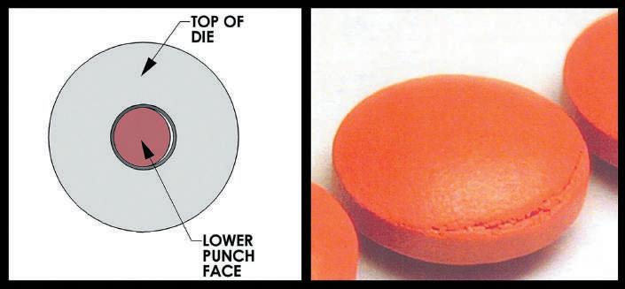
die bore be accurately centred to the punch tips. If not centred, the upper punch tip edge may strike the lead-in chamfer at the top of the die upon entry (Figure 2). Repetitive striking will quickly cause wear to the edge of the upper tip (Figure 3). With continued use, this edge wear can cause flashing on the tablets as previously described. The striking can be so severe that it may curl metal of the tip inwards into the cup. This condition is called J-hook and may cause capping and lamination of the tablets. Also, if the die bore is not well centred, the lower punch tip will have contact with the bore on one side with all the clearance on the opposite side. This increased clearance will allow product to sift into the gap, also potentially cause excessive wear previously described. It may also create a defect to the tablet on the lower edge where the tablet band and the cup face meet (Figure 4). How Can You Prevent Tip Wear? To prevent potential tip wear, good communication with your tooling supplier is vital. By having some forethought and seeking consultation regarding tooling material selection, periodic inspections of critical turret parts and adhering to proper press setup procedures can all work together to mitigate tip wear and extend tool life. Analyse Your Press Setup Press setup can be critical in reducing and preventing accelerated tip wear. Pre-loading is the process of twisting the keyed upper punch in the direction of turret rotation while using the upper punch to set the angular alignment of the die bore shape. Pre-loading simulates the rotational forces that the upper punch experiences when the press is in operation. When using shaped/
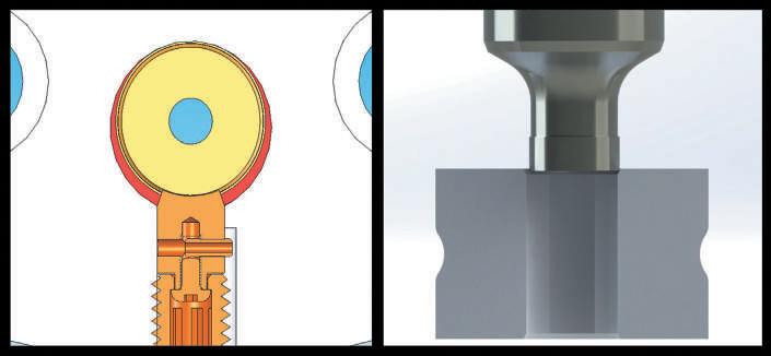
Figure 2. “Drop in” die pushed out of centre by die lock screw causing tip edge contact with the lead-in chamfer of the die punch tip and die bore, resulting in accelerated wear to the outer edge of the upper punch tip due to contact with the die bore as it enters. Following simple setup procedures such as pre-loading, combined with periodic turret inspections, can greatly reduce unnecessary tip wear.
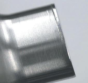
Figure 5. Tip damage from lack of pre-load
What Steel Type and Hardness is Right for Your Tooling? Selecting the proper steel type can help to reduce tip wear for abrasive granulates. Reputable tool vendors offer a variety of different steel types for challenging formulations. Abrasive wear-resistant tool steel grades include AISI (DIN) D2 (1.2379), M2 (1.3343), DC-53 and K-340. For very abrasive products, punches can be produced from premium wear-resistant PM grade steels (PM = particle metallurgy), such as, PM-3V, PM-9V and PM-10V. As the hardness increases on premium tool steels so does the abrasive
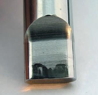
Figure 3. Resulting damage to punch tips Figure 4. Off-centre lower face and resulting tablet defect
Also, wear in the key slot of the upper punch guides on the turret can allow angular misalignment between the upper tip and the shape of the die bore. This may allow for opposite corner edge wear to the upper tip. This key slot wear can be addressed through the proper setup procedure called pre-loading, discussed later in the article. keyed tooling, pre-loading is often not practised. All presses have clearance in the key slot of the turret, which may increase further as the turret wears. If the punches are not pre-loaded when setting the die alignment, the upper punch will shift angularly as the turret rotates (Figure 8). This creates angular misalignment between wear-resistance, but it must be noted that the impact toughness decreases somewhat. Some steels are required to be cryogenic tempered (-184°C, -300°F) to increase wear-resistance and receive full return on investment. If your vendor does not offer this tempering process, the steel type or your tooling vendor should be reconsidered.
It is the combination of each steel’s unique chemistry and the related heat treatment process that allows the different steel types to attain their advantageous unique mechanical properties. This makes them ideal for the wear-resistance needed for abrasive formulations, yet still allows them to support the compression forces needed for the high-stress, high-cycle loading conditions of tablet compression.
Design of Tooling and Their Configuration The rotary “B” tool was designed more than 120 years ago, during the early stages of the industrial revolution, with the “D” tool design quickly following. Refinements, often called tool options, are commonly made to the basic tool design for better performance and to extend tool life. One of the most commonly used options is tapered dies. This option is typically used to resolve capping and laminating issues, and to make it easier to eject the tablet from the die. Aside from resolving these tabletting issues, tapered dies can help offset mild turret misalignment by guiding the upper tip into the bore, bypassing the potential contact with the lead-in chamfer. The amount and depth of taper can be customised and machined to meet individual tabletting needs and press setup requirements. Alignment of Turret Most turrets are manufactured in three sections. When a press experiences a sudden stoppage event or accident, this can shift a section out of alignment. If any section of the turret is out of alignment, this can lead to unnecessary contact between the punches and dies resulting in wear to the punch tips. Periodic turret inspections can mitigate this by identifying that a turret is no longer properly aligned. Tolerance Stacking Tolerance stacking refers to the condition where the dimensional and geometric tolerances on assembled parts (punches, tips, die O.D., die I.D., die pocket, punch guide, key, and key slot) combine to create the worst possible fit condition. In addition to alignment of critical components on the turret, tolerance stacking on the turret and tools combined, can also affect tip-to-die alignment. When all these tolerances are at their extremes, it creates a situation where punch-to-die contact is possible, even when all components are comfortably within tolerance. Inspecting the Tip for Punch Wear While proper inspection can help prevent many commonly encountered tabletting defects, the practice of punch tip inspection often only includes checking the size of the tip by measuring with a micrometer or calipers. Since the measuring anvils (contact surfaces) of these instruments are 3-6mm (0.120-0.250”) wide, they only check for the largest dimension. Often wear to the very edge of the punch tip is relatively small, undetectable using traditional measuring equipment and techniques and may not be easily observed by unassisted visual inspection. Some form of magnification is necessary to properly and thoroughly inspect punch tips for edge wear. The good news is that tip wear can be easily inspected using a horizontal optical comparator.
Visual inspection for tip edge wear is quite challenging, especially without magnification. A horizontal optical comparator (often called a comparator) is an apparatus that applies the principles of optics to the inspection of manufactured parts. In a comparator, the magnified silhouette of a punch tip is projected upon a screen, usually at 10x, but can also be at 20x or even greater magnification. The wear of the part can be easily inspected, and even measured against prescribed limits. Unfortunately, a comparator is not used often in the industry but is a valuable piece of equipment. Conclusion Punch tip edge wear can come from a variety of circumstances and may cause significant production quality-related issues. It is important to understand and know how to identify the most common causes of this type of wear. Punch tip edge wear can be difficult to detect because traditional methods of inspection are ineffective. Fortunately, the use of a horizontal optical comparator makes the inspection job easy – and fast. The most versatile piece of inspection equipment, a comparator provides a bright, crisp image for error-free inspection of the punch tips. Avoiding punch tip edge wear when possible, and quickly identifying when it does occur, will provide great benefits to the quality of your tablets and to your production operation.
Bill Turner
Bill Turner is the Technical Service Manager of Tooling and Tablets at Natoli Engineering Company, Inc. His previous positions at Natoli were Engineering Manager and Tablet and Tool Designer for 20 years, and Technical Customer Service Representative for more than 15 years. He educates and trains Natoli sales and service staff and conducts industry training seminars regarding tablet design, tool design, and troubleshooting.
Kevin Queensen
Kevin Queensen is a Mechanical Engineering and Technical Service Support at Natoli Engineering Company. His focus is primarily on specialty tablet/tooling designs along with determining new max compression force calculation methods and performing Finite Element Analysis (FEA).


