equipment for XL3 4000
equipment for XL3 4000
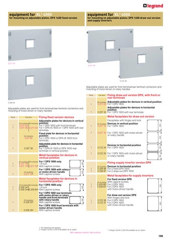
for mounting on adjustable plates: DPX 1600 fixed version
for mounting on adjustable plates: DPX 1600 draw-out version and supply invertors
100
0 211 10
100 150
0 211 15
0 212 34
150 200
Adjustable plates are used for front terminal/rear terminal connection and mounting of motor-driven or rotary handles
Metal faceplates for supply invertors
400 800 200 400 300 600 300 200 800 150 400 300 200 600 300 800 600 800
1
400 600 300
24 modules
1 1
For draw-out version DPX With hinges and lock 0 212 36 For 2 DPX 1600 0 212 37 For 2 DPX 1600 with motor-driven handle
Red catalogue numbers: New products
800
800
1 1
For fixed version DPX With captive screws 0 209 86 For 2 DPX 1600 0 209 871 For 2 DPX 1600 with motor-driven handle
400 600 600
Devices in horizontal position 0 206 86 For 2 fixed DPX 1600 0 206 87 For 2 draw-out DPX 1600
24 modules
600 200 300 400
1 1
800
Fixing supply invertor version DPX
200 400 150 600 100 150
100
0 212 35 For 1 DPX 1600 with motor-driven or rotary handle
400 800600
150100
1: For fastening and sealing 2: Hinges Cat.No 0 209 59 available as an option
150100 200 100 150 100 300 150 200
1
Devices in horizontal position 0 212 34 For 1 DPX 1600
400300 200 150
1
600
1
24 modules 36 modules For 1 DPX 1600 only 0 208 341 1/4 turn 0 209 342 0 209 842 With captive screws For 1 DPX 1600 rear terminals with motor-driven or rotary handle and front terminals with rotary handle 24 modules 2 0 209 35 With captive screws For 1 DPX 1600 front terminals with motor-driven handle 2 0 209 36 With captive screws
0 211 16 For 1 DPX 1600 with motor-driven or rotary handle
800 600
1
100 300 150 200
200 100 150
Metal faceplates for devices in horizontal position 1 1
1
Faceplates with hinges and lock Devices in vertical position 0 211 15 For 1 DPX 1600
24 modules
800
1
For 1 DPX 1600 only 0 211 101 1/4 turn 0 211 112 0 211 12 2 With captive screws For 1 DPX 1600 with rotary or motor-driven handle 24 modules 0 211 142 With captive screws
24 modules 36 modules
200 600 300 400
1 1
1
200 150 400 300
Metal faceplates for devices in vertical position
300 400 600
1
Adjustable plates for devices in vertical position 0 211 04 For 1 DPX 1600 with front terminals 0 211 06 0 211 03 For 1 DPX-IS 1600 or 1 DPX 1600 with rear terminals Fixed plate for devices in horizontal position 24 modules 0 211 00 For 1 DPX 1600 or DPX-IS 1600 front terminals Adjustable plate for devices in horizontal position 0 207 36 For 1 DPX-IS 1600 or DPX 1600 rear terminals in vertical position
24 modules 36 modules
Metal faceplates for draw-out version
800
1
Fixing fixed version devices
800 600 400
1 1
Cat.Nos
800
Pack
1
Adjustable plates for devices in vertical position 0 211 05 For 1 DPX 1600 Adjustable plates for devices in horizontal position 0 207 35 For 1 DPX 1600 with rear terminals
24 modules
100
Adjustable plates are used for front terminal/rear terminal connection and mounting of motor-driven or rotary handles
200 100 300
1
800
0 209 34
Fixing draw-out version DPX, with front or rear terminals
Cat.Nos
300 150 400100 100
Pack
1: Hinges Cat.No 0 209 59 available as an option
199
equipment for XL3 4000
solid faceplates and accessories for XL3 4000
for mounting on plate: DMX3 and DMX3-I fixed or draw-out version
0 207 51
0 208 44
0 209 59 Pack
0 200 51
Metal solid faceplates
Cat.Nos
1/4 turn For fastening and sealing 1 1 1 1 1 1 1
0 209 38
Faceplates with hinges and lock 24 modules 36 modules
0 209 38
Width 600 mm For 1 DMX3 2500/4000, N/H/L, 3P, or 1 DMX3 2500, N/H, 4P or 1 DMX3 -I 2500
100
24 modules 36 modules Height (mm)
0 209 90 0 209 91 0 209 92 0 209 93 0 209 94 0 209 95 0 209 96
200 300
0 212 45 0 212 47 0 212 48
100 150
0 209 40 0 209 41 0 209 42 0 209 43 0 209 44 0 209 45 0 209 46
150 200
100 100 150 100
1 1 1
1 1 1 1
Hinges Cat.No 0 209 59 available as an option 50 100 150 200 300 400 600 With hinges and lock 100 200 300
Accessories for natural ventilation
Assist natural ventilation Screw mounting 24 modules 36 modules Perforated faceplates 0 209 49 0 209 99 Height 200 mm Perforated panels 0 205 44 For plinth 725 mm width 0 205 45 For plinth 975 mm width Distance piece 0 205 46 Distance piece for roof heightening 300 400
Metal faceplates for DMX and DMX3 -I fixed or draw-out version 3
1
50 100 150 200 300 400 600 With captive screws
400 600
1
1 1 1 1 1 1 1
150 200 150
1
For DMX3 fixed version 0 207 51 For 1 DMX3 2500/4000, N/H/L, 3P/4P, and DMX3 -I Width 600 mm 0 207 52 For 1 DMX3 2500/4000, N/H/L, 3P/4P, and DMX3 -I Width 850 mm For DMX3 draw-out version 0 207 53 For 1 DMX3 2500/4000, N/H/L, 3P/4P, and DMX3 -I Width 600 mm 0 207 54 For 1 DMX3 2500/4000, N/H/L, 3P/4P, and DMX3 -I Width 850 mm
24 modules 36 modules
200 300 200
1
0 208 40 0 208 41 0 208 42 0 208 43 0 208 44 0 208 45 0 208 46
Fixing devices for DMX3 and DMX3 -I
300 400 300
1
Cat.Nos
400 600 400
Pack
Height (mm)
24 modules
200
Width 850 mm 0 209 48 For 1 DMX3 2500/4000, N/H/L, 3P/4P or 1 DMX3 -I 2500/4000
1
0 209 59
20 10
0 200 51 0 016 65
10
0 203 99
600 800 600
For 1 DMX3 -L 2500, 4P, or 1 DMX3 4000, N/H/L, 4P or 1 DMX3 -I 4000
800
1
0 209 39
800 850
1
800600
Accessories for faceplates Hinges Set of 2 Fit on screw mounting faceplates Blanking plates For metal or insulated faceplates 24 modules, smooth adjustable strip 18 modules, can be separated into modules or 1/2 modules Clip-on holder for adhesive labels Supplied with sheet of labels for marking rows on faceplate 24 modules
accessories and faceplates for XL3 4000
0 206 42 Pack
0 206 02
0 206 45 Cat.Nos
1 1
0 206 41 0 206 42
1 1 1
0 206 43 0 206 44 0 206 45
1
0 206 46
1 1 1 1 1
0 206 40 0 206 47 0 206 48 0 206 49 0 206 90
Universal plates Fit onto the functional uprights Perforated plates width 600 mm Height 200 mm Height 400 mm Solid plates width 600 mm Height 200 mm Height 400 mm Height 600 mm Solid plates width 850 mm Height 400 mm Adjustable solid plates Height 100 mm, width 600 mm Height 200 mm, width 600 mm Height 400 mm, width 600 mm Height 200 mm, width 850 mm Height 100 mm, width 850 mm
Pack
1 1
Supplied with depth adjustment runner 0 205 40 Height 1800 mm, width 600 mm
Universal 2 rails 1 1
Fit onto the functional uprights 0 206 04 Width 600 mm (24 modules) 0 206 54 Width 850 mm (36 modules)
Adjustable universal fixing devices
1 1
Comprising a 2 rail and 2 adjustable fixing brackets Fit onto the functional uprights 0 206 02 For 24 module cabinets and enclosures 0 206 52 For 36 module cabinets and enclosures
Wiring
Lina 25 ducting fixing supports For horizontal and vertical mounting and height adjustment of Lina 25 ducting Fit directly onto the functional uprights 0 204 70 Set of 2, for 36 module enclosures 0 205 70 Set of 2, for 24 module enclosures Lina 25 ducting Length: 2 m Width x Height (mm)
48 40 32 32
0 362 07 0 362 08 0 362 12 0 362 13
100
Isolating rivet 0 200 80 For fixing Lina 25 ducting on functional uprights
40 x 60 40 x 80 60 x 60 60 x 80
Accessories
Solid mounting plate 1
Cat.Nos
6
Clip nuts and screws 1/4 fastening on front panel 0 200 92 Clip nuts for M6 screws 0 200 91 M6 screws Aerosol paint spray 0 200 98 RAL 7035 - 400 ml
1 1 1
0 205 21 Set of 2 crosspieces length 350 mm 0 205 22 Set of 2 crosspieces length 600 mm 0 205 23 Set of 2 crosspieces length 850 mm
1
0 205 29 Set of 2 brackets for XL3 4000 - CEP Zucchini connection
50 20
Cable fixing supports
Roof reinforcement bracket
Lighting for panel 1
Lighting kit 0 209 89 Kit for metal XL3 800/4000, comprising fluorescent lamp, fixings and metal screw-mounting faceplate
201
forms of separation equipment for XL3 4000
Essential tool for all levels of forms XL PRO2 determines the partitioning and automatically inserts all the necessary cat.numbers according to required level of form
Designation
Top or bottom horizontal separation kit Front panel partitioning DMX3 Front panel side partitioning Horizontal partitioning for functional units
Kit for vertical separation between enclosure and cable sleeve
Kit for vertical separation between internal cable sleeve and external cable sleeve L-shaped separation kit for horizontal busbars 1600 A max. U-shaped separation kit for horizontal busbars 1600 A max. L-shaped separation kit for horizontal busbars 4000 A max.
main benefits
U-shaped separation kit for horizontal busbars 4000 A max.
• All level of form 1 to 4b • Choice of the connection method & the circuit diagram • Preview of the installation • Complete parts list and purchase order
U-shaped separation kit for horizontal busbars 1600 A max. U-shaped separation kit for horizontal busbars 4000 A max. U-shaped separation kit for horizontal busbars 1600 A max. U-shaped separation kit for horizontal busbars 4000 A max. Side vertical divider for DPX 1600 Side partition with and caps for functional units separation
Vertical partitionning for rear busbars
Partitionning for rear busbars
Horizontal busbar partitioning Rear vertical partitioning DPX compartment kit Partitionning for cell without horizontal busbars
Automatic calculation of partitioning
Bottom busbar area closure Rear partitioning divider for space compartment DMX3, compartment kit
MORE INFORMATION
www.legrand.com 202
XLPro2 software
width 24 modules width 36 modules
2a rear terminals 0 208 91 0 208 99
width 24 modules width 36 modules
0 208 08 0 208 09
Complementary information
Forms of separation and type of connection (terminals) 2b 3a 3b 4a front rear rear front rear front terminals terminals terminals terminals terminals terminals 0 208 91 0 208 91 0 208 91 0 208 99 0 208 99 0 208 99
4b rear terminals 0 208 91 0 208 99
0 208 08 0 208 09 0 208 68
width 24 modules width 36 modules
0 208 92 0 205 92
0 208 92 0 205 92
0 208 68 0 208 92 0 205 92
0 208 92 0 205 92
0 208 68 0 208 92 0 205 92
for enclosure depth 475 mm
0 208 27
0 208 27
0 208 27
for enclosure depth 725 mm
0 208 28
0 208 28
0 208 28
for enclosure depth 975 mm
0 208 29
0 208 29
0 208 29
for enclosure depth 475 mm
0 208 37
0 208 37
0 208 37
for enclosure depth 725 mm
0 208 38
0 208 38
0 208 38
for enclosure depth 975 mm
0 208 39
0 208 39
0 208 39
for enclosure depth 475 mm
0 205 36
0 205 36
0 205 36
for enclosure depth 725 mm
0 205 37
0 205 37
0 205 37
for enclosure depth 725 mm
0 205 38
0 205 38
0 205 38
for enclosure depth 975 mm
0 205 39
0 205 39
0 205 39
for internal cable sleeves depth 475 mm for internal cable sleeves depth 725 mm
0 208 70 0 208 71
0 208 70 0 208 71
0 208 70 0 208 71
for internal cable sleeves depth 725 mm for internal cable sleeves depth 975 mm
0 208 72 0 208 76
0 208 72 0 208 76
0 208 72 0 208 76
for external cable sleeves depth 475 mm for external cable sleeves depth 725 mm
0 208 73 0 208 74
0 208 73 0 208 74
0 208 73 0 208 74
for external cable sleeves depth 725 mm for external cable sleeves depth 975 mm
0 208 75 0 208 86
0 208 75 0 208 86
0 208 75 0 208 86
0 205 96 height 200 mm
0 205 96
0 205 96
0 205 97
0 205 97
height 300 mm
0 205 98
0 205 98
height 400 mm
0 205 99
0 205 99
0 208 92 0 205 92
for enclosure depth 725 mm for enclosure depth 975 mm
0 208 48 0 208 49
0 208 48 0 208 49
height 200 mm
0 208 77
0 208 77
height 300 mm
0 208 78
0 208 78
height 400 mm
0 208 79
0 208 79
for enclosure depth 725 mm for enclosure depth 975 mm
0 208 93 0 208 94
0 208 93 0 208 94
0 208 94
0 208 69
0 208 69
height 200 mm
0 208 87
height 300 mm
0 208 88
height 400 mm
0 208 89
to close last DPX compartment
0 208 95 0 208 96 0 208 97
width 24 modules width 36 modules
0 208 18 0 208 19
0 208 18 0 208 19
0 208 18 0 208 19
0 208 18 0 208 19
0 208 18 0 208 19
0 208 18 0 208 19
203
forms 2a to 4b for XL3 4000
n Definitions (standard EN 60439-1) Form 2a Separation of the busbars from the functional units The terminals for external conductors do not need to be separated from the busbars
n Rear terminals construction Form 2a Form 2a is simply obtained by using adjustable horizontal plates DPX must have rear terminals The busbar must be installed behind the functional uprights If the addition of further equipment in the enclosure is required, use solid plates When there is a gap between 2 plates, horizontal divider Cat. Nos 0 208 92 or 0 205 92 must be used to prevent any contact with the rear busbar
Form 2b Separation of the busbars from the functional units The terminals for external conductors are separated from the busbars
Horizontal partitioning Cat.No 0 208 92 or Cat.No 0 205 92 to fill the space between the plates Form 3a Separation of the busbars from the functional units, separation of the terminals for external conductors from the functional units and separation of all the functional units from one another The terminals for external conductors do not need to be separated from the busbars
Forme 2b Separation of the busbars from the functional units The terminals for external conductors are separated from the busbars The vertical busbar is placed behind the functional uprights The devices must be horizontal and with rear terminal connection
Form 3b Separation of the busbars from the functional units and separation of all the functional units from one another Separation of the terminals for external conductors from the functional units but not from each other The terminals for external conductors do not need to be separated from the busbars
Horizontal busbar partitioning Cat.No 0 208 93/94 Horizontal rear busbars partitioning Cat.No 0 208 84/85 Divider for rear terminals Cat.No 0 208 77/78/79
Form 4a Separation of the busbars and the functional units and separation of all the functional units from one another, including the terminals for external conductors which are an integral part of the functional unit The terminals for external conductors are in the same compartment as the functional unit The terminals for external conductors are separated from the busbars Form 4b Separation of the busbars and the functional units and separation of all the functional units from one another, including the terminals for external conductors The terminals for external conductors are not in the same compartment as the functional unit, but in individual, separate compartments
Form 3a Form 3a is obtained from form 2a by adding horizontal dividers Cat.No 0 208 92 or Cat.No 0 205 92 and front panel total dividers Cat.No 0 208 90 Horizontal partitioning Cat.No 0 208 92 or Cat.No 0 205 92 Front panel side partitioning Cat.No 0 208 90
204
Forms 3b, 4a
Form 3b For form 3b partitioning, it is advisable to start with form 2b and add: - Horizontal dividers between the functional units - Side partitions either side of the functional units Horizontal busbar partitioning Cat.No 0 208 93/94 Vertical rear busbars partitioning Cat.No 0 208 84/85 Front panel side partitioning Cat.No 0 208 68
Form 4b Connection on the rear terminals is obtained by using: - Closing partitions for busbars (vertical and horizontal) - Closing partitions for devices (horizontal and with rear terminals) - Closing partitions for output terminals - Closing partitions between cells that are joined together
For form 3b partitioning, it is advisable to start with form 2b and add: 1 - Horizontal dividers between the functional units 2 - Side partitions on either side of the functional units In 4a form, the outgoing connections must be made within the functional units Note: When connecting via front terminals, the incoming terminals must be fitted with terminal shield MCBs Separation kit for horizontal busbars in enclosure Cat.Nos 0 205 36/37/38/39 U-shaped separation kit for horizontal busbars in external cable sleeves Cat.Nos 0 208 73/74/75/86 Vertical separation kit between enclosure or internal/external cable sleeves Cat.Nos 0 205 33/34/35 Horizontal partitioning Cat.No 0 208 92 or Cat.No 0 205 92 Side partitions with end pieces Cat.No 0 205 97/98/99
Horizontal busbar partitioning Cat.No 0 208 94 DPX compartment kit Cat.No 0 208 87/88/89 Front panel side partitioning Cat.No 0 208 68
n Front terminals construction Form 2b The vertical busbar is positioned in a cable sleeve then separated from the functional units using a vertical separation kit between the enclosure and the cable sleeve (the cables and flexible bars can be fed through the front part) Use an L-shaped or U-shaped separation kit for the horizontal busbars These kits consist of a rear part (height 200 or 300 mm) and a horizontal divider across the whole of the usable depth Separation kit for horizontal busbars in enclosure Cat.Nos 0 205 36/37/38/39 U-shaped separation kit for horizontal busbars in external cable sleeves Cat.Nos 0 208 73/74/75/86 Vertical separation kit between enclosure or internal/external cable sleeves Cat.Nos 0 205 33/34/35
205
equipment selection for XL3 800
Device
Fully adaptable enclosures
Fixing
Position
XL3 800 - 24 modules fixing on din-rail Modular devices < 63 A
Cabinet or enclosure
vertical
Modular devices > 63 A
Cabinet or enclosure
vertical
Vistop 63 to 160 A
Cabinet or enclosure
vertical
DPX-IS 250
Cabinet or enclosure
vertical
fixing on plate
XL3 800 extendable enclosures 24 and 36 modules per row
DPX3 160 (Combinaison possible with DPX3 250)
Cabinet or enclosure
vertical
horizontal
DPX3 250 and DPX3 160-125 electronic (Combinaison possible with DPX3 160)
discover the range • Extendable: 24 and 36 modules • Two indexes of protection: IP 43 up to 800 A, supplied flat with functional uprights IP 55 up to 600 A, supplied without side panels • Takes: DIN rail equipment, DPX, DPX-IS and Vistop ≤ 800 A
Cabinet or enclosure
vertical
horizontal DPX-IS 250
Cabinet or enclosure
DPX 250 (Combination possible with DPX 630)
Cabinet or enclosure
vertical
vertical
horizontal DPX 630 (Combination possible with DPX 250)
Cabinet or enclosure
horizontal Cabinet or enclosure
DPX-IS 630
vertical
vertical
Cable sleeve
vertical
DPX-IS 1600
Cabinet or enclosure
vertical
DPX 1600
Cabinet or enclosure
XL3 800 cabinets, p. 208
vertical horizontal
XL3 800 - 36 modules fixing on din-rail Modular devices < 63 A
Cabinet or enclosure
vertical
Modular devices > 63 A
Cabinet or enclosure
vertical
Vistop 63 to 160 A
Cabinet or enclosure
vertical
DPX-IS 250
Cabinet or enclosure
vertical
DPX3 160
Cabinet or enclosure
vertical
DPX3 250
Cabinet or enclosure
vertical
DPX-IS 250
Cabinet or enclosure
vertical
DPX 250
Cabinet or enclosure
vertical
DPX 630
Cabinet or enclosure
vertical
DPX-IS 630
Cabinet or enclosure
fixing on plate
XL 800 enclosures, p. 209
Equipment, p. 213
3
MORE INFORMATION
DPX 1600
www.legrand.com 206
XLPro2 software
Cabinet or enclosure
1: With window adaptor, to be ordered separately, Cat.Nos below: 0 203 67: adaptor for DPX 125 earth leakage module 0 203 68: adaptor for DPX 160 earth leakage module 0 203 69: adaptor for DPX 250 ER earth leakage module 2: Faceplate supplied
vertical vertical horizontal
Type of device
Fixing device
Fixing plate
Faceplate for device Height (mm)
1/4 turn
Screw
XL3 800 - 24 modules 0 206 01
-
150
0 208 00
0 209 00
0 206 01
-
200
0 208 01
0 209 01
0 206 01
-
200
0 208 01
0 209 01
with modular devices
0 206 01
0 262 39
300
0 208 10
0 209 10
without side motor-driven handle
-
with side motor-driven handle
0 206 11 + 4 210 71
300
0 208 10
0 209 10
0 206 11 + 4 210 68
300
0 208 10
0 209 10
direct rotary handle
0 206 08 + 4 210 71
300
0 208 05
0 209 05
manual supply inverter
0 206 11 + 4 210 58
300
0 208 10
0 209 10
motor-driven supply inverter
-
0 206 13 + 4 210 58
300
0 208 10
0 209 10
with or without e.l.c.bs
-
0 206 15
150
0 208 13
0 209 13
without side motor-driven handle
-
0 206 11 + 4 210 72
300
0 208 10(2)
0 209 10
with side motor-driven handle
0 206 11 + 4 210 69
300
0 208 10(2)
0 209 10
direct rotary handle
0 206 08 + 4 210 72
300
0 208 05
0 209 05 0 209 10
manual supply inverter
-
0 206 11 + 4 210 58
300
0 208 10(2)
motor-driven supply inverter
-
0 206 13 + 4 210 58
300
0 208 10(2)
0 209 10
with or without e.l.c.bs
-
0 206 17
200
0 208 17
0 209 17
device only in central position
0 206 05
300
0 208 10
0 209 10
1 or 2 devices
0 206 05
300
0 208 06
0 209 06
1 to 3 devices, no e.l.c.bs
0 206 20
400
0 208 20
0 209 20
1 to 3 devices, with e.l.c.bs
0 206 22
600
0 208 22
0 209 22
motor driven supply invertor
0 206 68(2)
400
-
-
with or without e.l.c.bs
0 206 24
200
0 208 24
0 209 24
with or without e.l.c.bs + motor
0 206 21
200
-
0 209 24
1 to 3 devices, no e.l.c.bs
0 206 20
400
0 208 20
0 209 20
1 to 3 devices, with e.l.c.bs
0 206 22
600
0 208 22
0 209 22
with or without e.l.c.bs
0 206 23
300
0 208 23
0 209 23
device only
0 206 07
300
0 208 07
0 209 07
device only
0 206 27
1550/1950
-
0 204 41/42
device only
0 211 00
300
-
0 211 11
device only
0 211 00
400
0 211 10
0 211 13
0 211 00
400
0 208 34
0 209 34
device only
XL3 800 - 36 modules 0 206 51
-
150
-
0 209 50
0 206 51
-
200
-
0 209 51
0 206 51
-
200
-
0 209 51
with modular devices
0 206 51
0 262 39
300
-
0 209 60
without side motor-driven handle
-
with side motor-driven handle
0 206 61 + 4 210 71
300
-
0 209 60
0 206 61 + 4 210 68
300
-
0 209 60 0 209 60
manual supply inverter
-
0 206 61 + 4 210 58
300
-
without side motor-driven handle
-
0 206 61 + 4 210 72
300
-
0 209 60
0 206 61 + 4 210 72
300
-
0 209 60
with side motor-driven handle manual supply inverter
-
0 206 61 + 4 210 58
300
-
0 209 60
1 or 2 devices
-
0 206 55
300
-
0 209 60
no e.l.c.bs
-
0 206 70
400
-
0 209 70
with e.l.c.bs
-
0 206 72
600
-
0 209 72
no e.l.c.bs
-
0 206 70
400
-
0 209 70
with e.l.c.bs
-
0 206 72
600
-
0 209 72
device only
-
0 206 57
300
-
0 209 57
device only
-
0 211 02
400
-
0 211 12
device only
-
0 211 02
400
-
0 209 84
Red catalogue numbers: New products
207
distribution cabinets, cable sleeves and doors XL3 800
0 204 01
0 212 51
Distribution equipment and accessories p. 212 to 215
0 212 61
Dimensions and installation principle see e-catalogue I P 43 - IK 08 with kit and door IP 40 - IK 08 with door IP 30 - IK 07 without door Metal enclosures Can take devices up to 800 A Fireproof to 750 째C/5 s in accordance with IEC 60695-2-1 For installation in public buildings Capacity: 24 and 36 modules per row Cabinets RAL 7035, plinths RAL 7004 Supplied flat with functional uprights fitted on the back, adjustable cable entry plate and joining accessories (horizontal and vertical) Pack
Cat.Nos
Cabinets
Pack
Cat.Nos
Width 660 mm 24 modules per row 1 1
1 1
0 204 01 0 204 02
Height (mm)
Faceplate height (mm)
Width (mm) external usable
1050 1000 660 600 1250 1200 660 600 Width 910 mm Can incorporate a cable sleeve 36 or 24 modules (if internal cable sleeve) 0 204 06 1050 1000 910 850 0 204 07 1250 1200 910 850
208
0 204 26
1
0 204 27
1 1
0 204 46 0 204 47
Supplied with handle, interchangeable key barrels, to be ordered separately (p. 212) 2 points of locking: low and high Distance faceplate/door: - metal: 67 mm - glass: 63 mm Curved
Depth (mm)
230 230
For cabinet
230 230
Internal cable sleeves
1
Doors
Kit for internal cable sleeve Mounting on the right or left-hand side inside 910 mm wide cabinets Comprising: upright and mounting accessories For creating a cable sleeve usable width of 250 mm For cabinet height 1050 mm or 1095 mm, Cat.No 0 204 06/56 For cabinet height 1250 mm or 1295 mm, Cat.No 0 204 07/57 Solid faceplates with hinges and locks For internal cable sleeves height 1050 or 1095 mm For internal cable sleeves height 1250 or 1295 mm
1 1 1 1
Metal
0 212 51 0 212 52 0 212 56 0 212 57
Glass
0 212 61 0 212 62 0 212 66 0 212 67
Heigth (mm)
1050 1250 1050 1250
Width (mm)
660 660 910 910
IP 43 kit 1
0 201 30
Supplied ready to use Lenght 5.5 m for cabinets (width 660 and 910 mm), enclosures and cable sleeves
distribution enclosures, cable sleeves and doors XL3 800
0 204 04
0 204 09 + 0 204 29
0 204 29
p. 283
Optimised distribution
0 204 24
Dimensions and installation principle see e-catalogue I P 43 – IK 08 with kit and door IP 40 – IK 08 with door IP 30 – IK 07 without door Metal enclosures. Can take devices up to 800 A Fireproof to 750 °C/5 s in accordance with IEC 60695-2-1. For installation in public buildings Capacity: 24 and 36 modules per row. Enclosures RAL 7035, plinths RAL 7004 Supplied flat with functional uprights fitted on the back, adjustable cable entry plate and joining accessories (horizontal and vertical) Pack
Cat.Nos
Enclosures
Pack
Cat.Nos
Supplied with plinth, height 100 mm Width 660 mm 24 modules per row 1 1
1 1
0 204 03 0 204 04
Height (mm)
Faceplate height (mm)
Width (mm) external usable
1550 1400 660 600 1950 1800 660 600 Width 910 mm Can incorporate a cable sleeve 36 or 24 modules (if internal cable sleeve) 0 204 08 1550 1400 910 850 0 204 09 1950 1800 910 850
Supplied with handle, interchangeable key barrels, to be ordered separately (p. 225) Distance faceplate/door: - metal: 67 mm - glass: 63 mm Curved
Depth (mm)
230 230
230 230
For cabinet
1 1 1 1
Metal
0 212 53 0 212 54 0 212 58 0 212 59
Glass
0 212 63 0 212 64 0 212 68 0 212 69
1 1
0 204 28 0 204 29
1 1
0 206 78 0 206 79
1 1
0 204 48 0 204 49
Detailed dimensions and installation principle, see e-catalogue
Heigth (mm)
Width (mm)
1550 1950 1550 1950
660 660 910 910
External cable sleeves
Internal cable sleeves Kit for internal cable sleeves Mounting on the right or left-hand side inside 910 mm wide enclosures Comprising: upright and mounting accessories For creating a cable sleeve with a usable width of 250 mm For enclosure height 1550 mm, Cat.No 0 204 08/58 For enclosure height 1950 mm, Cat.No 0 204 09/59 Fixing devices For DPX 250 and 630 vertical For DPX 250 and 630 vertical with earth leakage module Faceplates with hinges and locks With cut-outs for DPX 250 or 630 with or without earth leakage module For internal cable sleeves height 1550 or 1595 mm For internal cable sleeves height 1950 or 1995 mm
Doors
Side cable sleeves Can be attached on the right or left-hand side Supplied with a plinth height 100 mm and joining accessories 1 1
0 204 23 0 204 24
1 1
0 206 28 0 206 29
1
0 204 43
1
0 204 44
1 1
0 204 33 0 204 34
1
0 201 30
Height (mm)
Faceplate height (mm)
Width (mm) external usable
Depth (mm)
1550 1400 460 400 230 1950 1800 460 400 230 Fixing devices For DPX 250 and 630 vertical For DPX 250 and 630 vertical with earth leakage module Faceplates with hinges and locks With cut-outs for DPX 250 or 630 with or without earth leakage module For external cable sleeves height 1550 or 1595 mm For external cable sleeves height 1950 or 1995 mm Doors For cable sleeves height 1550 mm For cable sleeves height 1950 mm
IP 43 kit Supplied ready to use Lenght 5.5 m for cabinets (width 660 and 910 mm), enclosures and cable sleeves
209
IP 55 distribution cabinets, cable sleeves and doors XL3 800
0 204 51
0 204 56
0 212 71
0 212 76
Dimensions and installation principle see e-catalogue IP 55 with door IK 08 Metal enclosures RAL 7035,plinths RAL 7004 Can take devices up to 630 A Fireproof to 750째C/5 s in accordance with IEC 60695-2-1 For installation in public buildings Capacity: 24 and 36 modules per row Can be joined horizontally For industrial external use and urban use undershelter Pack
Cat.Nos
Cabinets
Pack
Cat.Nos
Supplied without side panels Width 700 mm 24 modules per row 1 1
0 204 51 0 204 52
1 1
0 204 56 0 204 57
1 1
0 204 66 0 204 67
Height (mm)
Faceplate height (mm)
Supplied with handle, interchangeable key barrels, to be ordered separately (p. 212) Distance faceplate/door: 48 mm
Width (mm) external usable
1095 1000 700 1295 1200 700 Width 950 mm Can incorporate a cable sleeves 1095 1000 950 1295 1200 950 Side panels Set of 2 side panels For cabinet height 1095 mm For cabinet height 1295 mm
Doors
600 600
850 850
Depth (mm)
225 225
225 225
Metal
For cabinet Height (mm)
1095 1295 1095 1295
Width (mm)
1 1 1 1
0 212 71 0 212 72 0 212 76 0 212 77
700 700 950 950
1
0 205 85 Sealing kit IP 55 for use when joining cabinets together - length 5 m 0 204 861 Joining kit 0 204 82 Lifting rings Set of 2
Accessories 1 8
Internal cable sleeves
1
0 204 26
1
0 204 27
1 1
0 204 46 0 204 47
Kit for internal cable sleeves Mounting on the right or left-hand side inside 950 mm wide cabinets Comprising : upright and mounting accessories For creating a cable sleeves with a usable width of 250 mm For cabinets height 1050 or 1095 mm, Cat.No 0 204 06/56 For cabinets height 1250 or 1295 mm, Cat.No 0 204 07/57 Faceplates with hinges and locks For internal cable sleeves height 1050 or 1095 mm For internal cable sleeves height 1250 or 1295 mm For glass doors, Please consult us
For detailed dimensions and installation principle, see e-catalogue
1: For cabinets height 1095 and 1295, use 2 kits
210
IP 55 distribution enclosures, cable sleeves and doors XL3 800
0 204 54
0 204 59
Distribution equipment and accessories p. 212 to 215
0 204 74
Dimensions and installation principle see e-catalogue IP 55 with door IK 08 Metal enclosures RAL 7035, plinths RAL 7004 Can take devices up to 630 A Fireproof to 750째C/5 s in accordance with IEC 60695-2-1. For installation in public buildings Capacity: 24 and 36 modules per row Can be joined horizontally. For industrial external use and urban use undershelter Pack
Cat.Nos
Enclosures
Pack
Supplied with plinth height 100 mm Supplied without side panel Width 700 mm 24 modules per row 1 1
0 204 53 0 204 54
1 1
0 204 58 0 204 59
1 1
0 204 68 0 204 69
Height (mm)
Faceplate height (mm)
Width (mm) external usable
1595 1400 700 600 1995 1800 700 600 Width 950 mm Can incorporate a cable sleeve 36 or 24 modules (if integrated cable sleeve) 1595 1400 950 850 1995 1800 950 850 Side panels Set of 2 panels For enclosure height 1595 mm For enclosure height 1995 mm
0 204 28 0 204 29
1 1
0 206 78 0 206 79
1 1
0 204 48 0 204 49
Doors Supplied with handle, interchangeable key barrels (to be ordered separately, p. 212) Distance faceplate/door: 48 mm
Metal Depth (mm)
225 225
1 1 1 1
0 212 73 0 212 74 0 212 78 0 212 79
For cabinet Height (mm)
Width (mm)
1595 1995 1595 1995
700 700 950 950
External cable sleeves Side cable sleeves Can be attached on the right or left-hand side Supplied without side panels with a plinth height 100 mm
225 225
Internal cable sleeves
1 1
Cat.Nos
Kits for internal cable sleeves Mounting on the right or left-hand side inside 950 mm wide enclosures Comprising: divider, upright and mounting accessories For creating a cable sleeves with a usable width of 250 mm For enclosure height 1550 mm, Cat.No 0 204 08/58 For enclosure height 1950 mm, Cat.No 0 204 09/59 Fixing devices For DPX 250 and 630 vertical For DPX 250 and 630 vertical with earth leakage module Faceplates with hinges and locks With cut-outs for DPX 250 ou 630 with or without earth leakage module For internal cable sleeves height 1550 or 1595 mm For internal cable sleeves height 1950 or 1995 mm
1 1 1 1
1 1 1 1
Height (mm)
Faceplate height (mm)
Width (mm) external usable
Depth (mm)
0 204 73 1595 1400 500 400 225 0 204 74 1995 1800 500 400 225 Fixing devices 0 206 28 For DPX 250 and 630 vertical 0 206 29 For DPX 250 and 630 vertical with earth leakage module Faceplates with hinges and locks With cut-outs for DPX 250 or 630 with or without earth leakage module 0 204 43 For internal cable sleeve height 1550 or 1595 mm 0 204 44 For internal cable sleeve height 1950 or 1995 mm Doors 0 204 83 For external cable sleeve height 1400 mm 0 204 84 For external cable sleeve height 1800 mm
Accessories 1 1 8
0 205 85 Sealing kit IP 55 for use when joining cabinets together - length 5 m 0 204 861 Joining kit 0 204 82 Lifting rings Set of 2
1: For enclosures height 1595, use 3 kits For enclosures height 1995, use 4 kits
211
Accessories for XL3 800
cables fixing, plinths, dividers and accessories
With XL PRO2 Calculation you can… Calculate protection devices and cable section
0 204 36
0 201 95
main benefits • Easily edit all required technical documents • Gradually generate the wiring diagram of the entire installation • Automatically calculate the whole system, determining protection devices with their catalogue numbers and cable section • Preview the different reports containing technical data tables. Export drawings in DXF format and/or panel list to Excel
Pack
1 1 1
Cat.Nos
Cable fixing supports
0 204 35 For 660 mm wide cabinets 0 204 36 For 910 mm wide cabinets 0 204 37 For horizontal external cable sleeves
Plinths
1 1 1
For IP 43 enclosures 0 204 10 Width: 660 mm 0 204 11 Width: 910 mm 0 204 12 For cable sleeves width: 460 mm For IP 55 enclosures 0 204 60 Width: 700 mm 0 204 61 Width: 950 mm 0 204 62 For cable sleeves, width: 500 mm
1 1
0 204 90 For cabinets and enclosures, usable width: 600 mm 0 204 91 For cabinets and enclosures, usable width: 850 mm
1 1 1
Dividers for horizontal compartments
Accessories 1
Sotware calculates for you
MORE INFORMATION
1 1 1
Wall mounting lugs 0 201 00 Set of 4 metal lugs for IP 43 cabinets and enclosures Universal supports For mounting terminal blocks, earth terminals, etc. Set of 3 metal supports 0 201 96 For internal cable sleeves 0 201 95 For external cable sleeves Cable entry plate 0 204 20 Additional adjustable plate for XL3 800 - IP 43
Key barrels 1 1 1 1 1
www.legrand.com 212
XLPro2 Calculation
0 202 91 0 202 92 0 202 93 0 202 94 0 202 96
Supplied with a set of 2 keys Type 405 Type 455 Type 1242E Type 2433A Double bar knockout
equipment for XL3 800
equipment for XL3 800
for mounting on rail 2: modular devices (DX³, etc.), Vistop up to 160 A and DPX-IS 250, DPX3 160, DPX3 250
for mounting on plate: DPX-IS 250, DPX-IS 630, DPX-IS 1600
0 206 05
0 206 01
0 208 10 0 208 10
0 209 10
1
1
1 1
For 2 DPX-IS 250 0 208 061 1/4 turn 2 2 0 209 06 0 209 60 With captive screws
1 1
1
100 100200 100 150
For 1 DPX-IS 630 0 208 071 1/4 turn 0 209 072 0 209 572 With captive screws Does not allow the use of terminal shields Cat.No 0 262 45 For 1 DPX-IS 1600 in vertical position 24 modules 0 211 13 2 With captive screws
1 1
For modular devices 24 modules 36 modules 0 208 001 1/4 turn 0 209 00 2 0 209 50 2 With captive screws
1 1
For Vistop up to 160 A 0 208 011 1/4 turn 2 2 0 209 01 0 209 51 With captive screws
200 200200
200 200200
1 1
For DPX3 and DPX-IS 250 0 208 101 1/4 turn 0 209 10 2 0 209 60 2 With captive screws
300 300300
300 300300
400 400400
400 400400
1: For fastening and sealing 2: Hinges Cat.No 0 209 59 available as an option
150 200 300 150
1
150 150150
Metal faceplates
150 100
1 1
For DPX-IS 250 in central position 0 208 10 1/4 turn 2 2 0 209 10 0 209 60 With captive screws 24 modules 36 modules
200 200 400 300
1
Metal faceplates
300600 300 400
1
1
Direct fixing on fonctional uprights Fixed plates - front and rear terminals 0 206 05 0 206 55 For 1 or 2 DPX-IS 250 in vertical position 0 206 07 0 206 57 For 1 DPX-IS 630 in vertical position 0 211 00 For 1 DPX-IS 1600 or 1 DPX 1600 front terminals Cable sleeve 0 206 27 For 1 DPX-IS 630 in external cable sleeve
24 modules 36 modules
800 400 400 600
1
1 1 1
Plates for DPX-IS
Cat.Nos
800 600 600
1
Pack
800 800
1
Rails 3 Comprising: an aluminium profile rail and two 2-position fixing brackets Fit onto functional uprights Accept HX3 125 A row distribution blocks 24 modules 36 modules For mounting DPX using fixing plates 0 206 01 0 206 51 For fixing XL3 800 and XL3 4000 functional uprights Accept wire guide Cat.No 4 052 25 (p. 223) Fixing plates for mounting DPX³ on rail 2 For mounting DPX³ on aluminium rail 3 and on plate Cat.Nos 0 206 11/61 4 210 71 For DPX³ 160 without side motor-driven handle 4 210 73 For DPX3 160 with earth leakage module without side motor-driven handle 4 210 68 For all DPX³ 160 devices with side motor-driven handle 4 210 72 For DPX³ 250 without side motor-driven handle 4 210 74 For DPX3 250 with earth leakage module without side motor-driven handle 4 210 69 For all DPX³ 250 devices with side motor-driven handle Fixing plates for mounting DPX-IS 250 on rail 2 For mounting devices on aluminium rail 3 and on plate Cat.Nos 0 206 11/61 0 262 39 For DPX-IS 250 Rail height spacer Designed for simultaneous mounting of modular devices and DPX3 160/250 and DPX-IS 250 devices mounted on rail 3 Cat.Nos 0 206 01/51 or plate Cat.Nos 0 206 11/61 4 052 26 For 20 modules
100 100100
1
For DPX-IS 250, DPX-IS 630, DPX-IS 1600 and DPX 630
Fixing on rail 2
150 150150
1
Cat.Nos
100 100100
Pack
0 209 10
For installation principle, see e-catalogue
1: For fastening and sealing 2: Hinges Cat.No 0 209 59 available as an option
600 600600
600 600600
Red catalogue numbers: New products
213
equipment for XL3 800
equipment for XL3 800
for mounting on plate: DPX 160 and DPX 250 3
for mounting on plate: DPX 250, DPX 630 and DPX 1600
3
0 206 11
0 206 17
0 206 20
0 206 24
Installation principle see e-catalogue
300 300 400 400 800
For 1 DPX 1600 0 211 10 2 1/4 turn (1) 1 1 0 211 11 0 211 12 With captive screws
24 modules
1 1
0 208 24 0 209 242
1 1
0 208 231 0 209 23 2
1 1
1
Metal faceplates - devices in horizontal position For 1 DPX 250 with or without earth leakage module 1/4 turn With captive screws For 1 DPX 630 with or without earth leakage module 1/4 turn With captive screws
24 modules 36 modules For 1 DPX 1600 0 208 342 1/4 turn 0 209 341 0 209 841 With captive screws
Red catalogue numbers: New products
600 600
600 600
100100
1 1
200200 100 300300 150 400 200 400
1 1
For 1 to 3 DPX 250 and 630 with downstream earth leakage module 0 208 22 2 1/4 turn 0 209 221 0 209 721 With captive screws
1: For fastening and sealing 2: Hinges Cat.No 0 209 59 available as an option
214
150150
100 100 150 150 200 200 100 300 300 150
24 modules 36 modules For 1 to 3 DPX 250 and DPX 630 only 0 208 20 2 1/4 turn 0 209 201 0 209 701 With captive screws 400 400 200
1 1
100 100 600 100600 300
For DPX³ 250 in horizontal position 1/4 turn With captive screws
Metal faceplates - devices in vertical position
200 200 200 600 800800 150 150 150 400
150 150 400
0 208 171 0 209 172
0 206 68
1
Devices in vertical position with motor-driven control Supplied with faceplate For 2 DPX 250
800 300 300 300
0 208 13 0 209 13 2
1 1
Kit for supply inverter
400 400 400
1 1
For DPX³ 160 in horizontal position 1/4 turn With captive screws
1
1
1: For fastening and sealing 2: Hinges Cat.No 209 59 available as an option 600 600 600
0 208 051 0 209 05 2
24 modules
100 100 600 600 300
1 1
For DPX³ in vertical position with direct rotary handle 1/4 turn With captive screws
200 200 600 800 800
1 1
24 modules 36 modules
1
100 100 600 600 300
200 200 100
For DPX in vertical position without direct rotary handle 0 208 101 1/4 turn 0 209 10 2 0 209 60 2 With captive screws 0 209 27 With captive screws for DPX³ 250 with terminal shields 3
1
300 300 150
Metal faceplates
2
400200 400
1 1
1
Devices in vertical position 0 206 20 0 206 70 For 1 to 3 DPX 250 or 630 0 206 22 0 206 72 For 1 to 3 DPX 250 or 630 with earth leakage module 0 211 00 0 211 02 For 1 DPX-IS 1600 or 1 DPX 1600 front terminal Devices in horizontal position For cut-out protection for cable passing, use seal Cat.No 0 202 40 (p. 222) 0 206 21 For 1 DPX 250 with or without earth leakage module, motordrives 0 206 24 For 1 DPX 250 with or without earth leakage module 0 206 23 For 1 DPX 630 with or without earth leakage module 0 211 00 0 211 02 For 1 DPX-IS 1600 or 1 DPX 1600 front terminal
24 modules 36 modules
150 150 400
0 206 11 0 206 61 Equipped with a rail 3 for fixing DPX³ The DPX³ must be equipped with a fixing plate Cat.Nos 4 210 68/69/71/72 or plate for manual supply inverter Cat.No 4 210 58 Designed for simultaneous mounting of DPX3 160/250 and modular equipment (with spacer Cat.No 0 262 99) 0 206 08 Plate for DPX³ with direct rotary handle The DPX3 must be equipped with a fixing plate Cat.Nos 4 210 68/69 0 206 13 Plate for motor-driven supply inverter The DPX3 must be equipped with a fixing plate Cat.No 4 210 58 Devices in horizontal position For cut-out protection for cable passing, use seal Cat.No 0 202 40 (p. 222) 24 modules 0 206 15 For 1 DPX³ 160 0 206 17 For 1 DPX³ 250
150 150
1
1 1
200 200 600 800 800
1
24 modules 36 modules
Direct fixing on functional uprights Devices in vertical position
Plates for fixed version DPX, with front terminal Direct fixing on functional uprights
Cat.Nos
300 300
1
Plates for fixed version DPX3 with front terminals
Réf.
100 100
Emb.
Pack
400 400 800
0 208 13
accessories and faceplates XL3 800
0 200 92
0 206 42 Pack
0 209 59
0 206 02 Cat.Nos
1 1
0 206 41 0 206 42
1 1 1
0 206 43 0 206 44 0 206 45
1
0 206 46
Universal plates
0 209 45 Pack
Cat.Nos
1 1 1 1 1 1 1
24 modules
0 208 40 0 208 41 0 208 42 0 208 43 0 208 44 0 208 45 0 208 46
Universal rails 2
1 1
Fit onto functional uprights 0 206 04 Width 600 mm (24 modules) 0 206 54 Width 850 mm (36 modules)
Adjustable universal fixing devices 1 1
Comprising a rail 2 and 2 adjustable fixing brackets Fit onto functional uprights 0 206 02 For 24 modules cabinets and enclosures 0 206 52 For 36 modules cabinets and enclosures
Accessories 20 50 6
Clip nuts and screws 1/4 fastening on front panel 0 200 92 Clip nuts for M6 screws 0 200 91 M6 screws Aerosol paint spray 0 200 98 RAL 7035 - 400 ml
1 1 1 1 1 1 1
Lighting kit 0 209 89 Kit for metal XL3 800/4000, comprising fluorescent lamp, fixings and metal screw-mounting faceplate
0 209 40 0 209 41 0 209 42 0 209 43 0 209 44 0 209 45 0 209 46
0 209 90 0 209 91 0 209 92 0 209 93 0 209 94 0 209 95 0 209 96
1
0 209 59
20 10
0 200 51 0 016 65
10
0 203 99
1 1
56 48 40 32 32 100
0 362 02 0 362 07 0 362 08 0 362 12 0 362 13
Width (mm)
50 100 150 200 300 400 600 Hinges Set of 2 hinges Fit on screw mounting faceplates Blanking plates For metal or plastic faceplates 24 modules, smooth adjustable strip 18 modules, separable into module or 1/2 module Clip-on holder for adhesive labels Supplied with a sheet of labels for marking rows on faceplate 24 modules
Accessories for natural ventilation
Wiring Lina 25 ducting mounting supports For horizontal and vertical mounting and height adjustment of Lina 25 ducting Supplied with plastic rivets 0 204 70 Set of 2, for 36 modules cabinets and enclosures 0 205 70 Set of 2, for 24 modules cabinets and enclosure Lina 25 ducting Length: 2 m
Height (mm)
50 100 150 200 300 400 600 Captive screws Hinges Cat.No 0 209 59 available as an option
24 modules 36 modules Height (mm)
Lighting for panel 1
Solid metal faceplates 1/4 turn For fastening and sealing
Fit onto functional uprights Perforated width 600 mm Height 200 mm Height 400 mm Solid plates width 600 mm Height 200 mm Height 400 mm Height 600 mm Solid plates width 850 mm Height 400 mm
Assist natural ventilation Screw mounting 0 209 49 0 209 99 Height 200 mm
24 modules 36 modules
1
Height (mm)
25 60 40 60 40 80 60 60 60 80 Plastic rivet 0 200 80 For fixing Lina 25 ducting on functional uprights
215
equipment selection for XL3 400
Be free to organize your enclosures XL 400 self-assembly cabinets and enclosures, IP 43 metal or insulated 3
Device
Fixing
Position
Cabinet or enclosure
vertical
Cable sleeve
vertical
Cabinet or enclosure
vertical
Cable sleeve
vertical
Vistop 63 to 160 A
Cabinet or enclosure
vertical
DPX-IS 250
Cabinet or enclosure
vertical
Fixing on din-rail Modular devices < 63 A
Modular devices > 63 A
Fixing on PLATE
DPX3 160 (Combination possible with DPX³ 250)
Cabinet or enclosure
vertical
horizontal Cable sleeve
vertical
main benefits • Optimised transport and stocking thanks to flat packaging • Optimised use of space inside enclosures thanks to external cable sleeve that can be equipped with DPX MCCBs • Takes: DIN rail equipment, DPX, DPX-IS and Vistop ≤ 400 A
DPX3 250 (Combination possible with DPX³ 160)
Cabinet or enclosure
vertical
horizontal Cable sleeve DPX-IS 250
vertical
Cabinet or enclosure
vertical
Cable sleeve
vertical
Cabinet or enclosure
vertical
DPX 250 horizontal Cable sleeve
vertical
XL 400 cabinets, p. 218 3
Cabinet or enclosure
vertical
DPX 630 horizontal
DPX-IS 630
XL3 400 enclosures, p. 218
Cable sleeve
vertical
Cabinet or enclosure
vertical
Equipment, p. 220
MORE INFORMATION
www.legrand.com 216
XLPro software 2
1: With window adaptor, to be ordered separately, Cat.Nos below: 0 203 67: adaptor for DPX 125 earth leakage module 0 203 68: adaptor for DPX 160 earth leakage module 0 203 69: adaptor for DPX 250 ER earth leakage module
Type of device
Fixing device
Fixing plate
0 202 06 0 202 01
Faceplate for devices Height (mm)
Metal
-
150
0 203 00
0 202 03
-
150
0 203 03
0 202 06 0 202 01
-
200
0 203 01
0 202 03
-
200
0 203 04
0 202 06 0 202 01
-
200
0 203 01
with modular devices
0 202 06
0 262 09
300
0 203 10
with or without e.l.c.bs and without direct rotary handle
-
0 202 11 + 4 210 71
300
0 203 10
with or without e.l.c.bs and with direct rotary handle
-
0 202 11 + 4 210 68
300
0 203 10
0 202 09
300
0 203 09
manual supply inverter(2)
-
0 202 11 + 4 210 58
300
0 203 10
with or without e.l.c.b
-
0 202 13
150
0 203 13
with or without e.l.c.b
-
0 202 17
300
0 203 18
with or without e.l.c.b and without side motor-driven handle
-
0 202 11 + 4 210 72
300
0 203 10
with or without e.l.c.b and with side motor-driven handle
-
0 202 11 + 4 210 69
300
0 203 10
0 202 09
300
0 203 09
manual supply inverter(2)
-
0 202 11 + 4 210 58
300
0 203 10
with or without e.l.c.bs
-
0 202 15
200
0 203 17
with or without e.l.c.bs
-
0 202 17
300
0 203 18
device only in central position
0 202 05
300
0 203 10
device only
0 202 18
300
0 203 18
direct rotary handle(1)
direct rotary handle
(1)
1 to 2 devices, no e.l.c.bs
0 202 20
400
0 203 20
device only in central position
0 202 21
400
0 203 21
1 to 2 devices, with e.l.c.bs
0 202 22
600
0 203 22
centred with e.l.c.bs
0 202 23
600
0 203 23
with or without e.l.c.bs
0 202 24
200
0 203 24 0 203 28
device only
0 202 28
400
with downstream e.l.c.bs
0 202 29
800
0 203 29
1 device, no e.l.c.bs
0 202 20
400
0 203 20
device only centred
0 202 21
400
0 203 21
1 device, with e.l.c.bs
0 202 22
600
0 203 22
centred with e.l.c.bs
0 202 23
600
0 203 23
without downstream e.l.c.bs
0 202 25
300
0 203 25
device only
0 202 28
400
0 203 28
with downstream e.l.c.bs
0 202 29
800
0 203 29
device only
0 202 07
400
0 203 07
Red catalogue numbers: New products
217
distribution cabinets and enclosures XL3 400
0 201 19
0 201 39
p. 282
Optimised distribution
0 201 05
Dimensions and installation principle see e-catalogue Take devices up to 400 A Fireproof to 750 째C/5 s in accordance with IEC 60 695-2 for installation in public buildings (up to 100 kVA for Class II cabinets) Capacity: 24 modules per row Enclosures RAL 7035, plinths RAL 7004 Door to be ordered separately Supplied flat with functional uprights fitted on the back, adjustable cable entry plate and joining accessories (horizontal and vertical) Pack
Cat.Nos
Metal cabinets
Pack
IP 43 - IK 08 with kit and door IP 40 - IK 08 with door IP 30 - IK 07 without door To be equipped 1 1 1 1 1 1
0 201 03 0 201 04 0 201 05 0 201 06 0 201 07 0 201 08
1 1 1 1 1 1
0 201 23 0 201 24 0 201 25 0 201 26 0 201 27 0 201 28
Height (mm)
Faceplate height (mm)
600 550 750 700 900 850 1050 1000 1200 1150 1500 1450 External cable sleeves 600 550 750 700 900 850 1050 1000 1200 1150 1500 1450
Width total (mm) usable (mm)
575 575 575 575 575 575
515 515 515 515 515 515
310 310 310 310 310 310
250 250 250 250 250 250
Cat.Nos
IP 43 - IK 08 with kit and door IP 40 - IK 08 with door IP 30 - IK 07 without door To be equipped Supplied with plinth, height 100 mm
Depth (mm)
175 175 175 175 175 175 175 175 175 175 175 175
Metal enclosures
1 1
1 1
0 201 18 0 201 19
Height (mm)
Faceplate height (mm)
Width total (mm) usable (mm)
1600 1450 575 1900 1750 575 External cable sleeves Supplied with plinth, height 100 mm 0 201 38 1600 1450 310 0 201 39 1900 1750 310
515 515
250 250
Depth (mm)
175 175
175 175
For XL3 400 insulating and IP 55 distribution cabinets, Please consult us
For detailed dimensions and installation principle, see e-catalogue
218
doors and equipment for XL3 400
0 202 55
0 201 21
0 202 73
Pack
0 202 59
Cat.Nos
Metal doors Supplied with handle with interchangeable key barrels (to be ordered separately) Curved Faceplate/door distance: 57 mm
Metal
1 1 1 1 1 1 1
1 1 1 1 1 1 1
0 202 53 0 202 54 0 202 55 0 202 56 0 202 57 0 202 58 0 202 59
Metal
Glass
0 202 731 0 202 831 0 202 741 0 202 841 0 202 751 0 202 851 0 202 761 0 202 861 0 202 771 0 202 871 0 202 781 0 202 881 0 202 791 0 202 891 Metal
1 1 1 1 1 1 1
0 201 63 0 201 64 0 201 65 0 201 66 0 201 67 0 201 68 0 201 69
For cabinet/enclosure Height (mm)
Distribution equipment and accessories p. 220 to 223
0 202 83
600 750 900 1050 1200 1500/1600 1900 Flat Faceplate/door distance: metal-38 mm; glass-34mm 600 750 900 1050 1200 1500/1600 1900 Flat for cable sleeves Faceplate/door distance: 38 mm 600 750 900 1050 1200 1500/1600 1900
Pack
Cat.Nos
1 1 1 1
0 202 91 0 202 92 0 202 93 0 202 94
1
0 201 30
Equipment for doors Key barrels for metal or transparent doors Supplied with a set of 2 keys Type 405 Type 455 Type 1242 E Type 2433 A Seal for IP 43 protection Supplied ready to use length 5.5 m for cabinets (width 660 and 910 mm), enclosures and cable sleeves
Self-adhesive document holders for plan Open - RAL 7035 20 20 1
10
0 365 80 0 365 81
External dim. Height Width (mm) (mm)
Height (mm)
Internal dim. Width (mm)
235 340 200 310 165 260 130 230 Closed - RAL 9002 0 365 82 Rigid plastic - IP 50 Internal dim.: 324 x 120 x 18 mm
Depth (mm)
18 18
Transparent 0 097 99 Flexible plastic - A4 - 305 x 220 mm
Mounting accessories 1 1
0 201 10 0 201 12
1
0 201 20
1
0 201 00
1
0 201 21
Plinths Height 100 mm For cabinets and enclosures For cable sleeves Cable entry plates Additional adjustable plate for XL3 400 metal Wall mounting lugs Set of 4 metal lugs for IP 43 cabinets and enclosures Plates with knock-out entries 2 x Ă&#x2DC;4 to 32 mm and 22 x Ă&#x2DC;4 to 20 mm For XL3 400 metal For curved glass doors, Please consult us 1: Not suitable for Vistop with front handle
219
equipment for XL3 400
for mounting on rail 3: modular devices (DX³, etc.), Vistop up to 160 A, DPX3 160, DPX3 250 and DPX-IS 250
for mouting on plate: DPX3 160, DPX3 250 and DPX-IS 250
0 202 11
0 202 06
0 202 01
equipment for XL3 400
0 202 13
0 203 00
0 203 01
Installation principle see e-catalogue Pack
Cat.Nos
Fixing rails 2
0 203 10
Comprising: a rail 2 and 2 fixing brackets Fit onto functional uprights Take wire guides Cat.No 0 200 94
1
1
1 position rail 2 For modular devices and Vistop up to 160 A 0 202 01 For fixing on XL3 400 functional uprights only
4 210 71 4 210 73
1
4 210 68
1 1
4 210 72 4 210 74
1
4 210 69
1
Cat.Nos
1
0 202 11
1
0 202 09
1 1
0 202 13 0 202 15
2 positions aluminium rail 2 For DPX and DPX-IS 250 with plates Accepts HX3 125 A row distribution blocks 0 202 06 For fixing on XL3 400 functional uprights only Accepts wire guide Cat.No 4 052 25 (p. 223)
1 1
1
Pack
Fixing plates for mounting DPX³ on rail 2 For mounting DPX3 on aluminium rail 3 Cat.No 0 202 06 or on plate Cat.No 0 202 11 For DPX3 160 without side motor-driven handle For DPX3 160 with earth leakage module without side motor-driven handle For all DPX3 160 devices with side motor-driven handle For DPX3 250 without side motor-driven handle For DPX3 250 with earth leakage module without side motor-driven handle For all DPX3 250 devices with side motor-driven handle
Adaptors for mounting DPX-IS 250 on rail 2 For mounting devices on aluminium rail 3 Cat.No 0 202 06 and on plate Cat.No 0 202 11 0 262 39 For DPX-IS 250 Rail height spacer Designed for simultaneous mounting of modular devices and DPX3 160/250 and DPX-IS 250 devices mounted mounted on rail 3 Cat.No 0 202 06 or on plate Cat.No 0 202 11 4 052 26 For 20 modules
1 1
1 1 1
0 203 10 0 203 11 0 203 09
1
0 203 13
1
0 203 17
1/4 turn fastening and sealable For modular devices 0 203 00 Height 150 mm For Vistop up to 160 A 0 203 01 Height 200 mm For DPX3 or DPX‑IS 250, and Vistop up to 160 A 0 203 10 Height 300 mm
Red catalogue numbers: New products
220
Fit on to functional upright Vertical mounting Equipped with a rail 3 for fixing DPX³ or DPX-IS 2501 The DPX³ or the DPX-IS 250 must be equipped with a fixing plate Cat.Nos 4 210 68/69/71/72 and Cat.No 0 262 39 or plate for manual supply inverter Cat.No 4 210 58 Designed for simultaneous mounting of DPX3 160/250 and DPX-IS and modular equipment (with spacer Cat.No 0 262 99) Plate for DPX3 with direct rotary handle The DPX3 must be equipped with a fixing plate Cat.Nos 4 210 68/69 Horizontal mounting For cut-out protection for cable passing, use seal Cat.No 0 202 40 For 1 DPX3 160 thermal-magnetic For 1 DPX3 250 or 1 DPX³ 160 electronic release
Metal faceplates
Metal faceplates
1
Plates for fixesd version with front terminals
1/4 turn fastening and sealable For DPX3 and DPX-IS 250 in vertical position Height 300 mm Height 400 mm for DPX3 250 with terminal shields Height 300 mm for DPX3 160/250 with direct rotary handle For DPX3 160 in horizontal position Height 150 mm For DPX3 250 in horizontal position Height 200 mm
equipment for XL3 400
equipment for XL3 400
for mouting on plate: DPX 250, 630 and DPX-IS 630
for mouting devices on rail 2 or on plate in cable sleeves
0 202 03
0 202 20
0 203 03
0 202 24
0 202 17
0 203 18
Installation principle see e-catalogue
0 203 20
Fixing on rail with faceplates for modular devices up to 160 A Fixing on plates with faceplates for DPX3 160, 250, DPX 250, 630 and DPX-IS 250
0 203 24
Installation principle see e-catalogue Emb.
Rテゥf.
1 1
0 202 071 0 202 201
1 1
0 202 211 0 202 221
1
1 1
0 202 231
0 202 24 0 202 251
Plates for fixed version devices with front terminals
Emb.
An additional rail can be installed 2 Fit onto functional uprights Devices in vertical position For 1 DPX窶選S 630 For 1 to 2 DPX 250 or 1 DPX 630 and 1 DPX 250 or 1 DPX 630 only or 1 DPX 250 with 1 distribution block Cat.No 0 374 00 For 1 DPX 250 or 1 DPX 630 in central position For 1 to 2 DPX 250 with e.l.c.b. or 1 DPX 630 and 1 DPX 250 with e.l.c.b. or 1 DPX 630 only or 1 DPX 250 with e.l.c.b. with 1 distribution block Cat.No 0 374 00 For 1 DPX 250 or DPX 630 with earth leakage module in central position Device in horizontal position For cut-out protection for cable passing, use seal Cat.No 0 202 40 (p. 222) For 1 DPX 250 with or without earth leakage module For 1 DPX 630 without earth leakage module
Metal faceplates for devices in vertical position
1
1 1
1
1/4 turn fastening and sealable For DPX-IS 630 0 203 071 Height 300 mm For 1 to 2 DPX 250 For 1 DPX 630 and 1 DPX 250 or 1 DPX 630 only or 1 DPX 250 with 1 distribution block Cat.No 0 374 00 0 203 201 Height 400 mm For 1 DPX 250 or 1 DPX 630 in central position 0 203 211 Height 400 mm For 1 to 2 DPX 250 with e.l.c.b. For 1 to 2 DPX 250 with e.l.c.b. or 1 DPX 630 and 1 DPX 250 with e.l.c.b. or 1 DPX 630 with e.l.c.b. or 1 DPX 250 with e.l.c.b. with 1 distribution block Cat.No 0 374 00 0 203 221 Height 600 mm
1
Rテゥf.
Fixing on rail 2 modular devices and Vistop up to 160 A
0 202 03 Comprising a rail 2 and 2 fixing brackets Fit onto functional uprights Take wire guides Cat.No 0 200 94 Capacity: 9 modules
1/4 turn faceplates for mounting on rail 2
1 1
1/4 turn fastening and sealable for devices on rail 2 For modular devices 0 203 03 Height 160 mm For modular devices and Vistop up to 160 A 0 203 04 Height 200 mm
Plates for fixed version devices with front terminals 1 1 1
Devices in vertical position Fit onto functional uprights 0 202 17 For DPX3 160 and DPX3 250 0 202 281 For DPX 250 or DPX 630 0 202 291 For DPX 250 or DPX 630, with downstream earth leakage module
Metal faceplates for mounting on plates
1 1
1/4 turn fastening and sealable for devices on plates For DPX3 and DPX-IS 250 0 203 18 Height 300 mm 0 203 27 Height 400 mm for DPX3 250 with terminal shields
1
0 203 281 Height 400 mm
1
For DPX 250 and 630 For DPX 250 and 630 with earth leakage module
0 203 291 Height 800 mm
For 1 DPX 250 or 1 DPX 630 in central position with e.l.c.b. 1
0 203 231 Height 600 mm
Metal faceplates for devices in horizontal position 1 1
1/4 turn fastening and sealable 0 203 24 Height 200 mm for 1 DPX 250 0 203 25 Height 300 mm for 1 DPX 630 1: Limited to 400 A
1: Limited to 400 A Red catalogue numbers: New products
221
accessories and faceplates for XL3 400
0 201 60 0 202 41
0 200 92 Pack
0 203 41 Cat.Nos
1 1 2
0 202 41 0 202 42 0 202 43
100 100
0 364 40 0 364 41
1
0 201 60
1
1
1
1 1
1 1
20 50 6 1 1
222
0 201 45
0 203 99
Accessories Perforated universal plates Fit directly onto functional uprights Height 200 mm for cabinets and enclosures Height 300 mm for cabinets and enclosures Height 300 mm for cable sleeves Clips nuts for perforated plates For M4 screws For M5 screws Finishing strip For a perfect finish at the join between DLP trunking and XL3 cabinets or enclosures RAL 7035
Universal rail 2 0 202 04 Fits onto functional uprights Width 515 mm Universal adjustable fixing device 0 202 02 Comprising a rail 2 and 2 adjustable fixing brackets Fits onto functional uprights of XL3 400 Insulating fixing support 0 200 90 Set of 2 supports Fits directly on functional uprights in XL3 400/800 cabinets or enclosures For creating an insulated earth with 12 x 4 mm copper bar (Cat.No 0 373 49) or flat bar 12 x 2 mm (Cat.No 0 048 19) and IP 2X terminal block Also takes universal rails Cat.Nos 0 202 04, 0 206 05/54 Cable fixing support For fixing ties for holding cables in place on entry to the cabinet 0 201 35 For cabinets and enclosures 0 201 37 For cable sleeves Universal support For mounting terminal blocks, earth terminalsâ&#x20AC;Ś Set of 3 metal supports 0 201 96 For internal cable sleeves Divider 0 201 90 For horizontal compartmentalisation Clip nuts for functional uprights 1/4 turn fastening on front panel 0 200 92 Clip nuts for M6 screw Screws 0 200 91 M6 screws Aerosol paint spray 0 200 98 RAL 7035 - 400 ml Lighting kit 0 203 89 For mounting on supplied plate Protection seal 0 202 40 For cut-out protection on plate Length 20 m, can be cut to length
Pack
Cat.Nos
1/4 turn solid faceplates For cabinets and enclosures Fastening and sealable
Metal
1 1 1 1 1
0 203 40 0 203 41 0 203 42 0 203 43 0 203 44
1 1 1 1 1 1 1 1 1 1
0 201 41 0 201 42 0 201 40 0 201 43 0 201 44 0 201 45 0 201 46 0 201 47 0 201 48 0 201 49
20 10
0 200 51 0 016 65
10
0 203 99
Height (mm)
50 100 150 200 300 For cable sleeves 50 100 200 550 700 850 1000 1150 1450 1750 Blanking plates RAL 7035 24 modules, smooth adjustable strip 18 modules, separable into modules or 1/2 modules Clip-on holder for adhesive labels Supplied with sheet of labels for marking rows on faceplate
wiring and connection accessories for XL3 400
0 201 70
0 373 00
0 201 93 Pack
1
56 48 40
2 x 0 375 12 + 1 x 0 373 00 mounted Cat.Nos
Wiring
Pack
Lina 25 ducting fixing support 0 201 70 Set of 2 supports For fixing and height adjustment of Lina 25 ducting: - vertical: 40 x 60 or 40 x 80 - horizontal: 40 x 60 Supplied with insulating rivets Fit directly onto functional uprights Can not be used for 150 mm spacing between rails, except when equiped with Lina 25 ducting 25 mm width Lina 25 ducting Length: 2 m 0 362 02 0 362 07 0 362 08
50
0 367 74
100
0 200 80
10
0 200 94
10
0 201 93
1
4 052 25
Width (mm)
Height (mm)
25 60 40 60 40 80 Insulating screw M6 x 10 Insulating rivet For fixing Lina 25 ducting on functional uprights Wire guides For horizontal wiring Fits directly on rail 2 Takes brass bar Cat.No 0 373 00 and bar 12 x 4 with clamps Cat.No 0 373 02 For vertical wiring Fits directly onto functional uprights in XL3 400 cabinets and enclosures For horizontal wiring Fits directly on to 2-position aluminium rail Accepts Lina 25 ducting covers
Connection of protective conductor
10
0 048 19
1
0 373 00
1
0 373 01
1
0 373 02
Flat bar 12 x 2 Takes IP 2X terminal blocks Fits onto functional uprights in XL3 400 cabinets and enclosures, or on insulating supports Cat.No 0 200 90 Length: 1 meter Additional brass bar Length 416 mm, 12 x 6.5 mm cross-section Fits directly on integrated supports in XL3 160 cabinet or on rail 2 with wire guides Cat.No 0 200 94 or on support end stop Cat.No 0 375 12 - 36 holes Ø5.3 mm (1.5 to 10 mm2) - 2 holes Ø9 mm (35 mm2) Brass bar for protective conductor Length 456 mm, 12 x 6.5 mm cross-section - 36 holes Ø5.3 mm (1.5 to 10 mm2) - 2 holes Ø9 mm (35 mm2) - 4 holes Ø6.5 mm (2.5 to 16 mm2) Fits onto functional uprights with supplied lugs Flat copper bar 12 x 4 with clamps Supplied with clamp connectors (40 x 1.5 to 4 mm2, 4 x 6 to 16 mm2, 1 x 35 mm2) Length 455 mm Fits onto functional uprights in XL3 400 cabinets and enclosures or on rail with wire guides Cat.No 0 200 94
1
10 100 10 10
10
100
10
Cat.Nos
Connection of protective conductor (continued)
Equipotential link conductor 0 373 85 Length 350 mm Cross-section 6 mm2, ensures equipotential continuity when fitting auxiliaries on door (Osmoz signalling units > 50 V) No perforated copper bar 0 373 49
Cross section (mm)
Permis. I (A)
Length (mm)
12 x 4 180 991.5 Connectors for bar 12 x 4 without holes 0 373 60 1.5 to 4 mm2 0 373 61 6 to 16 mm2 0 373 62 10 to 35 mm2 (supplied with M6 screws 5 mm) Copper bar with tapped holes 0 373 89
Cross section Permis. I (mm) (A)
Tapped holes Ø (mm) Pitch
Length (mm)
12 x 4 160 M5 18 990 Connectors for 12 x 4 mm bar with tapped holes 0 373 65 1 or 2 conductors from 1.5 to 10 mm2 (supplied with Ø5 screws) Support end cap 0 375 12 For rails 2 15 mm depth and 2 EN 60715 7.5 mm (except rail fixed on plate) and 15 mm depth Takes the following protection or shielding bars: - Brass bar Cat.Nos 0 373 00/01 - Copper bar 12 x 4 mm with clamps Cat.No 0 373 02 - IP 2X terminal block with flat steel bar 12 x 2 mm Cat.No 0 048 19 - Copper bar 12 x 4 mm Cat.Nos 0 373 49 or 0 373 89 - Shielding bar 10 x 3 mm Cat.No 0 375 34 (p. 327)
223
surface mounting cabinets XL3 160 "ready to use" distribution cabinets
0 200 06
0 200 45
0 200 54 + finishing strip 0 201 60
0 201 50
0 200 71
Technical characteristics p. 226 Doors and equipment p. 225 Removable chassis with rails 2 fitted Brass bar for protective conductors fitted: 36 holes 1.5 to 10 mm2 and 2 x 35 mm2 holes. Capacity 24 modules per row. RAL 7035 Supplied complete with rails and faceplates. Doors to be ordered separately (p. 225) For creating assemblies certified in accordance with IEC EN 60439-1 Removable side panels. Removable, separable top and bottom panels for inserting adjustable cable gland plate Pack
Cat.Nos
XL3 160 metal cabinets
Pack
Cat.Nos
Fireproof to 750 °C/5 s in accordance with IEC 60695-2-1 for installation in public buildings IP 43 – IK 08 with seal and door IP 40 – IK 08 with door IP 30 – IK 07 without door Fully modular Can take DPX 125 1
0 200 02
No of rows
2
No of modules
48
Height (mm)
450
Width (mm)
575
Depth (mm)
147
Enclosures for creating class II (or totally isolated) assemblies in accordance with IEC EN 60439-1/3 IP 43 – IK 07 with seal and door IP 40 – IK 07 with door IP 30 – IK 04 without door Wire guide rings for vertical wiring Can take DPX 125 200 200 200
1
0 200 03
3
72
600
575
147
XL3 160 insulating cabinets
150
1
0 200 52
No of rows
2
No of modules
48
Height (mm)
450
Width (mm)
575
Depth (mm)
147
200
0 200 04
4
96
750
575
147
150 150
1
0 200 53
3
72
600
575
147
200
1
0 200 54
4
96
750
575
147
5
120
900
575
147
150 150 150
200
1
0 200 55
5
120
900
575
147
200
200
1
0 200 06
6
144
1050
575
147
1
0 200 56
6
144
1050
575
147
1
0 200 45
0 200 46
Fully modular with DPX 160 space 5 120 900 575 147
6
144
1050
575
147
50
Accessories for metal cabinets
300 150 150
1
200
1
50 300
1
150 150 150
1
200
Cable entry plates 0 200 20 Additional adjustable plate Cable fixing support 0 200 35 Holds cable in place on entry to cabinet Wall mounting lugs 0 201 00 Set of 4 metal lugs for IP 43 cabinets and enclosures Plate with knock-out entries 0 200 21 2 x Ø4 to 32 mm and 22 x Ø4 to 20 mm
Accessories for insulating cabinets 1 1
224
150 150 150 150 200
200
1
150 150 150 200
200
150 150 150 150
150 150 200
200
0 200 05
150 200
200
1
200 200
200
1
200
Wall mounting lugs 0 201 50 Set of 4 plastic lugs for insulating cabinets Plate with knock-out entries 0 200 71 2 x Ø4 to 32 mm and 22 x Ø4 to 20 mm
XL3 160
doors, equipment, wiring, connection of protective conductor
0 203 99
0 200 00
0 200 93
0 373 00 0 202 55 Pack
0 202 73
0 202 83
Doors
Cat.Nos
Pack
For XL3 160 flush and surface mounting cabinets Supplied with handle with interchangeable barrels (to be ordered separately) Curved Faceplate/door distance: metal - 57 mm 1 1 1 1 1
1 1 1 1 1
Metal
Glass
0 202 72 0 202 82 0 202 731 0 202 831 0 202 741 0 202 841 0 202 751 0 202 851 0 202 761 0 202 861 1
1 1
0 262 08 0 262 09
1
0 262 99
20 10
0 200 51 0 016 65
10
0 203 99
For cabinet/enclosure Height (mm):
0 202 52 0 202 53 0 202 54 0 202 55 0 202 56
Metal
1
450 600 750 900 1050 Flat Faceplate/door distance: metal - 38 mm; glass - 34 mm 450 600 750 900 1050
0 202 91 0 202 92 0 202 93 0 202 94
1
0 201 30
Key barrels for metal or transparent doors Supplied with a set of 2 keys Type 405 Type 455 Type 1242E Type 2433A Seal for IP 43 protection Supplied ready to use length 5.5 m for cabinets (width 660 and 910 mm), enclosures and cable sleeves
10
1
1
Self-adhesive document holders for plan
1
Open - RAL 7035 External dim. Height Width (mm) (mm)
20 20
0 365 80 0 365 81
1
0 365 82
10
0 097 99
235 165
340 260
0 200 00 Insulating
1
0 203 60
1
0 203 91
Fixing plates For fixing devices on rail 2 For DPX 125 or downstream earth leakage module For DPX 160, DPX 250 ER or downstream earth leakage module Rail height spacer Fits on a rail 2; used to mount on the same row DX and DPX/DPX-IS mounted on plate Cat.Nos 0 262 08/09/39 For 20 modules Blanking plates RAL 7035 For metal or plastic faceplates 24 modules, smooth adjustable strip 18 modules, separable per module or 1/2 module Clip-on holders for adhesive labels Supplied with sheet of labels for marking rows on faceplate 24 modules
Internal dim. Width (mm)
Depth (mm)
200 130
310 230
18 18
Closed - RAL 9002 Rigid plastic - IP 50 Internal dim.: 324 x 120 x 18 mm Transparent Flexible plastic - A4 - 305 x 220 mm
Universal rail Rail 2 Modular faceplate Height 300 mm
Solid faceplate
Wire guide 0 200 94 For horizontal wiring Fits directly on the rails 2 Takes brass bar Cat.No 0 373 00 and 12 x 4 bar with clamps Cat.No 0 373 02 0 200 93 For vertical wiring Fits directly on cabinet chassis - Set of 2 Ducting support 0 200 70 For direct vertical mounting of Lina 25 ducting Fits directly on cabinet chassis - Set of 2 Finishing strip 0 201 60 For a perfect finish at the join between DLP trunking and XL3 cabinet or enclosures RAL 7035
Connection of protective conductors
Height (mm)
1
1
Equipment for cabinet with DPX 160 space 1
Equipment for fully modular cabinets
Wiring
Equipment for doors
1 1 1 1
Cat.Nos
1
Additional brass bar 0 373 00 Length 416 mm, 12 x 6.5 mm cross-section Fits directly on the supports integrated in XL3 160 cabinet or on rail 2 with wire guides Cat.No 0 200 94 or on the support end stop Cat.No 0 375 12 - 36 holes Ă&#x2DC;5.3 mm (1.5 to 10 mm2) - 2 holes Ă&#x2DC;9 mm (35 mm2) Support for IP 2X terminal block 0 200 50 Set of 2 supports Fit directly at the back of cabinets (horizontal or vertical position) Takes 12 x 2 flat bar Cat.No 0 048 19 (p. 190) Equipotential link conductor 0 373 85 Length 350 mm Cross-section 6 mm2, ensures equipotential continuity when fitting auxiliaries on door (Osmoz signalling units > 50 V)
Height 100 mm
1: Not suitable for Vistop with front handle
For curved glass doors, Please consult us
225
surface mounting cabinets XL3 160 "ready to use" distribution cabinets
n Dimensions
n Installation principle
H (mm) 450 600 750 900 1050 900 1050 450 600 750 900 1050
Cat.Nos 0 200 02 0 200 03 0 200 04 0 200 05 0 200 06 0 200 45 0 200 46 0 200 52 0 200 53 0 200 54 0 200 55 0 200 56
H
575
Removable chassis
Fixing cables and wiring Cat.No 0 200 35
Vertical wire guide Cat.No 0 200 93
Support for Lina 25 ducting Cat.No 0 200 70
226
A (mm) 38 34
147
A
Metal Glass
With curved door (metal) 147
170
With flat door
190
Side panels can be removed separately
57
flush-mounting cabinets XL3 160
flush-mounting cabinets XL3 160
"ready to use" distribution cabinets
"ready to use" distribution cabinets
n Installation principle
Removable chassis
0 200 13 + door 0 202 83 (p. 227)
Doors and equipment p. 225
Fixing cables fitted
Fireproof to 750 °C/5 s in accordance with IEC 60695-2-1 for installation in public buildings Supplied complete: - metal flush-mounting box, - removable chassis with rails fitted, - brass bar for protective conductors fitted: 36 holes 1.5 to 10 mm2, 2 x 35 mm2 holes, - finishing frame and plastic faceplates Flush-mounting depth: 100 mm min. Capacity: 24 modules per row RAL 7035 Doors to be ordered separately (p. 225) Can take DPX 125 units IP 40 – IK 08 with door IP 30 – IK 04 without door Pack
1
Cat.Nos
0 200 13
Fully modular cabinets No of rows
3
Front panel No of Height Width modules (mm) (mm)
72
695
670
Box Height Width (mm) (mm)
640
617
200 150 200 200
1
0 200 14
4
96
845
670
790
617
Vertical wire guide Cat.No 0 200 93
150 150 200 200
1
0 200 15
5
120
995
670
940
617
150 150 150 200
n Dimensions
200
1
0 200 16
6
144
1145
670
1090
617
150 150 150 150
A
Fixing accessory 1
B
200
0 200 10 For hollow partition
670
Cat.Nos 0 200 13 0 200 14 0 200 15 0 200 16
A (mm) 640 790 940 1090
100
40
B (mm) 695 845 995 1145
227
NEW
surface mounting cabinets XL3 125 from 18 to 72 modules
4 018 56
4 016 79
4 016 78
4 016 77
4 016 76
4 016 79 + 4 018 64
4 016 77 + 4 018 72
4 018 44
4 018 51
Technical characteristics p. 229 IP 40 - IK 09 with door IP 30 - IK 09 without door Class II Self-extinguishing: resistance to incandescent wire 650째 Conform to IEC 60439-3 and IEC 60670-24 Pack
Cat.Nos
Surface-mounting distribution cabinets Capacity 18 modules per row White RAL 9003 Fully reversible cabinet (base, door and faceplates) Supplied with: - removable and pivoting chassis with 4 rails fitted. Rails can be individually removed for easy cabling on site - removable cable entry plate (top and bottom) - removable faceplates (for each row) - IP 2X screw terminal blocks for neutral and earth - blanking plates (5 modules, separable per module or 1/2 module) - 1 sheet of self-adhesive labels for circuit identification (marking per module) Spacing between rails 150 mm Adjustable 4 rail (2-position) for fitting modular equipment or DPX 125 moulded case circuit breakers Can be fitted with perforated plates and solid faceplates for mounting non-modular products (2, 3 to 4-row cabinets) Doors to be ordered separately
1 1 1 1
4 016 76 4 016 77 4 016 78 4 016 79
Number of rows
1 2 3 4
Number of modules
18 36 54 72
Height (mm)
300 450 600 750
Width (mm)
Pack
2
2 1 2
20 2
Depth (mm)
450 450 450 450
128 128 128 128
1 5
Cat.Nos
Key lock 4 018 51 To be fitted on white or transparent doors Supplied with key N째 850 Horizontal or vertical joining kit 4 018 45 For joining 2 cabinets Fixing lugs 4 018 56 Set of 4 wall fixing lugs Document holder 4 018 44 Self-adhesive document holder for plans To be fitted on the cabinet Blanking plates Separable per module or 1/2 module 0 016 60 5 modules - white RAL 9003 Plain faceplates 4 018 55 For 2, 3 or 4-rows cabinets Allow fitting of non-modular equipments such as control and signalling units Perforated plates To be used instead of the one 4 rail when integrating non-modular products 4 018 53 For 18 modules cabinets. Height 150 mm Fixing accessory for Arteor wiring devices 4 018 50 For fixing 2-module mechanisms on the side of the cabinet
Doors - IP 40 - IK 09
1 1 1 1
4 018 61 4 018 62 4 018 63 4 018 64
1 1 1 1
4 018 71 4 018 72 4 018 73 4 018 74
For XL3 125 distribution cabinets Fully reversible Can be equipped with lock and key n째 850 Cat.No 4018 51 White RAL 9003 For distribution cabinet Cat.No 4 016 76 For distribution cabinet Cat.No 4 016 77 For distribution cabinet Cat.No 4 016 78 For distribution cabinet Cat.No 4 016 79 Transparent For distribution cabinet Cat.No 4 016 76 For distribution cabinet Cat.No 4 016 77 For distribution cabinet Cat.No 4 016 78 For distribution cabinet Cat.No 4 016 79
Red catalogue numbers: New products
228
Accessories
surface mounting cabinets XL3 125 from 18 to 72 modules
■ Number of connections per neutral and earth terminal block (supplied with enclosure) Neutral terminal blocks Screw connection
Enclosure Cat.Nos
Earth terminal blocks Screw connection
6 - 25 mm2
1.5 - 16 mm2
6 - 25 mm2
1.5 - 16 mm2
4 016 76
1
17
1
17
4 016 77
1
21
1
21
4 016 78
1
26
1
26
4 016 79
1
34
1
34
■ Number of blanking plates supplied per enclosure Enclosure Cat.Nos
Number of blanking plates 5 modules
4 016 76
1
4 016 77
2
4 016 78
3
4 016 79
3
■ Dimensions Side view without door
Side view with door
A
Front view
450
128.2
Enclosure Cat.Nos
A (mm)
B (mm)
4 016 76
300
250
4 016 77
450
365
4 016 78
600
515
4 016 79
750
665
B
150
Fixing centres and distance between rails
150
260
229
Solutions for any type of installation A wide range of cabinets for 4 rail equipment available in different standards, designed for optimised wiring, maximum ease of installation and time-saving
DISCOVER THE RANGES British standard distribution boards • to 22 modules consumer units or • 125 and 250 A distribution boards
new Flush-mounting consumer units, p. 232
Surface mounting consumer units, p. 232
XL³-N 250 distribution cabinets, p. 236
Weatherproof cabinets & enclosures • Plexo 3 IP 65 cabinets for 4 rail equipment, from 2 to 72 modules • Atlantic and Atlantic-E IP 66 metal cabinets for industrial and commercial applications • Marina IP 66 polyester cabinets and enclosures, adapted to corrosive environment
Plexo3 cabinets, p. 238 230
Atlantic, Atlantic-E and Marina cabinets & enclosures, p. 240 to 257
MORE INFORMATION Get detailed information on many digital or printed supports, or contact your Area Commercial Manager
www.legrand.com
E-catalogue
QR-code
XL3-N 250 cabinets brochure
231
BS consumer units
BS consumer units
flush and surface mounting
flush and surface mounting
n Metal IP 41 - IK 08
225 160
258
47.5 14
5 B
Conform to EN 60439-3 Supplied completely assembled with neutral and earth terminals Pack
1 1 1
Cat.Nos
10 97
A C
6 075 04
6 010 44
73
Cat.Nos 6 010 42 6 010 44 6 010 46
A 210 281 353
Dimensions B 250 321 393
C 140 211 283
Ø25 3 5 6
Flush mounting boxes
Metal IP 41 - IK 08 with white metal door 6 010 42 8 modules units (6 available MCB ways) 6 010 44 12 modules units (10 available MCB ways) 6 010 46 16 modules units (14 available MCB ways)
n Plastic IP 30 - IP 07 4 to 22 module units A C
113
1 1
6 075 00 6 075 01
1 1 1
6 075 02 6 075 04 6 075 06
Plastic IP 30 – IK 07 with transparent lens Beige 4 to 8 module units Comprising: • One neutral + one earth terminals • One supply busbar • Isolating shield 4 modules units 8 modules units (with five blanking plates) 12 to 22 module units Removable pan assembly Comprising: • Two neutral + one earth terminals • Five blanking plates • One supply busbar • Isolating shield 12 modules units 16 module units 22 modules units
For accessories Please consult us
232
B A
Surface mounting boxes
Cat.Nos 6 075 00 6 075 01 6 075 02 6 075 04 6 075 06
A 140 212 298 370 478
Dimensions B C 225 90 225 162 225 268 225 340 225 448
Removable pan assembly
D 144 144 180 180 180
Top bottom Ø32 Ø25 1 3 1 5 1 6
Ø32 1 1 1
flush-mounting cabinets PractiboxTM 6 to 36 modules
flush-mounting cabinets PractiboxTM 6 to 36 modules
Lateral, top and bottom knock-out entries
Mounting of chassis with levelling system
Faceplate with integrated door
n Dimensions 6 011 11
Cabinets 6,8 and 12 modules
6 011 14
IP 40 - IK 07 with door Class II Conform to standard IEC 439 Reversible faceplate Box for masonry White RAL 9003 Supplied without terminal block
C
Terminal shield boxes 1 row of 6 modules 1 row of 8 modules 1 row of 12 modules 2 rows of 12 modules 3 rows of 12 modules
Accessories
10
1
A B C D E
Number of modules 8 mod. 12 mod. 266 334 188 225 244 287 180 208 27 31
Cabinets 24 and 36 modules C
334
80
289
150
20
Blanking plate Separable into modules or 1/2 modules 0 016 60 5 modules - white Terminal blocks 6 012 90 Neutral and earth - 2 x 8 holes Key lock Only for 2 and 3 rows distribution cabinets 0 019 66 N째 850
6 mod. 230 186 208 180 27
A B C
A
6 011 10 6 011 11 6 011 12 6 011 13 6 011 14
A
B
Cat.Nos
72
D B
Pack
1/12 1/12 1/6 1/5 1/3
E
Number of modules 24 mod. 36 mod. 376 526 358 508 40 42
Bold pack quantities: Minimum quantities to be ordered
233
surface mounting cabinets Nedbox
surface mounting cabinets Nedbox
8 to 48 modules
8 to 48 modules
n Distribution cabinets 2, 3 or 4 rows of 12 modules G
A
6 012 15
A : insulating base B : chassis/rail C : cover D : plastic or metal door E : sealing caps
boxes
Doors
Plastic doors - polycarbonate
Pre-cut part for trunking systems For 2, 3 and 4 rows cabinets
1 1 1 1
51
A C
318 285
E
20
D B
10
72
20 20 20
97
72
Accessories
0 014 91 Lock for Cat.Nos 6 012 42/43/44 0 013 89 Sealing kit 109 Blanking plates Separable into modules or 1/2 modules 20 0 016 60 5 modules - white 10 0 016 62 13 modules - white Terminal blocks for 1 row of 8 modules 10 6 012 90 Neutral and earth - 2 x 8 holes Terminal blocks for 1, 2, 3 and 4 rows of 12 modules 10 6 012 91 Neutral and earth - 2 x 12 holes 10 6 012 92 Earth - 30 holes 10 6 012 93 Neutral - 30 holes
125
6 012 15 For Cat.No 6 012 40 6 012 16 For Cat.No 6 012 41 6 012 17 For Cat.No 6 012 42 6 012 18 For Cat.No 6 012 43 6 012 19 For Cat.No 6 012 44 White Metal doors 6 012 26 For Cat.No 6 012 41 6 012 27 For Cat.No 6 012 42 6 012 28 For Cat.No 6 012 43 6 012 29 For Cat.No 6 012 44
285 Space under rail
6 012 05 6 012 06 6 012 07 6 012 08 6 012 09
100 130
130 190
318
Dimensions
White tinted
A
1 1 1 1 1
130 190
125
Transparent blue
For 1 row cabinets 52
Cover fixing with quick motion screws 1 row of 8 modules 1 row of 12 + 1 modules Fast locking by flip latch 2 rows of 12 + 2 modules 3 rows of 12 + 3 modules 4 rows of 12 + 4 modules
F : blanking plates G : fixation for cables H : fixation for terminal blocks
51
1 6 012 40 1 6 012 41 1 6 012 42 1 6 012 43 1 6 012 44
Locking of cover without tool
F
B
Cat.Nos Distribution
B
E
A
Pack
H
61
IP 40 - IK 07 with door IP 30 - IK 05 without door Class II - White RAL 9010 Conform to EN 60439-3 Self extinguishing 650째 C Polysterene material Can be equipped with reversible plastic or metal door Chassis can be clipped removed and tipped back to facilitate cabling Supplied without terminal blocks (see below)
61
6 012 09
D
B
6 012 44
C
Lateral space
72
1 1
52
109 24 mod. 36 mod. 48 mod. 100 225 350 475 380 505 630 130
A B
A C
E
97
234
10
D B
72
Space under rail
Lateral space
A B C D E
8 mod. 225 210 195 180 14
12 mod. 317 240 287 150 9
pour exemple terminal shield: xxxxxxx boxes
terminal shield boxes
xxxxxxxx 2 to 6 modules
2 to 6 modules
n Dimensions 4 modules
140
2 modules
52
0 013 58
87
6 modules
0 013 57
0 013 56
IP 30 Conform to EN 60439-3 Self extinguishing: 850° C Supplied without terminal blocks Class II White RAL 9010 Covers can be sealed
0 013 56 0 013 57 0 013 58
Terminal shield boxes Capacity in 17.5 mm modules
2 modules 4 modules 6 modules
Dimensions (mm) Height x Width x Thickness
140 x 52 x 68 140 x 87 x 68 140 x 130 x 68
68
130
n Mounting 4 holes Ă&#x2DC;7
5
50 30 20
Cat.Nos
120
Pack
48
36
72
114
235
XL3 - N 250 3-phase distribution boards
6 094 54
6 094 61
3-phase distribution boards for DIN-rail mounting circuit breakers; IP 40 - IK 08 with door Conform to standard IEC 61439-3; Type tested; ASTA certified Maximum voltage 480 V¹ ; Rated short-time withstand current (Icw) : 17 kA 0.2 s ; Rated peak withstand current (Ipk) : 34 kA Ambient temperature: 50 °C continuously Zinc coated metal; Grey RAL 7035 Supplied with: surface or flush-mounting box, reversible door with handle, faceplate, fully isolated tin plated copper busbar, earth and neutral distribution terminal blocks; The number of holes of earth and neutral terminal blocks are equal to the number of outgoing devices Pack
Cat. Nos
Flushmounting
Surface mounting
Flush-mounting distribution boards
Maximum rating 125 A To be equipped with mounting kit for main circuit breaker (DIN-rail mounting MCBs or DRX 100 MCCBs) No of poles (outgoing terminals)
1 1 1 1 1 1 1 1
6 094 50 6 094 51 6 094 52 6 094 53 6 094 54 6 094 55 6 094 56 6 094 57
6 094 70 6 094 71 6 094 72 6 094 73 6 094 74 6 094 75 6 094 76 6 094 77
12 18 54 30 36 42 48 54 Maximum rating 250 A To be equipped with mounting kit for main circuit breaker (DIN-rail mounting MCBs, DRX 100 or DRX 250 MCCBs) No of poles (outgoing terminals)
1 1 1 1 1 1 1
6 094 58 6 094 59 6 094 60 6 094 61 6 094 62 6 094 63 6 094 64
6 094 78 6 094 79 6 094 80 6 094 81 6 094 82 6 094 83 6 094 84
Pack
18 54 30 36 42 48 54
Cat. Nos
Flushmounting
Maximum rating 125 A To be equipped with mounting kit for main circuit breaker (DIN-rail mounting MCBs) No of poles (outgoing terminals)
1 1 1 1 1 1 1 1 1
6 054 10 6 054 12 6 054 14 6 054 16 6 054 18 6 054 20 6 054 22 6 054 24 6 054 26
6 054 11 6 054 13 6 054 15 6 054 17 6 054 19 6 054 21 6 054 23 6 054 25 6 054 27
1
6 054 93
20
6 054 94
10
6 016 65
Red catalogue numbers: New products
236
Surface mounting
Split type busbar distribution boards
12 + 12 12 + 18 12 + 24 12 + 30 12 + 36 18 + 18 18 + 24 18 + 30 18 + 36
Accessories
Fixing supports for terminal blocks Kit consisting of 2 insulated fixing supports for terminal blocks for earth Insulating caps For protecting unused outgoing terminals of the busbar Blanking plate RAL 7035 Separable into modules or 1/2 modules 18 modules
XL3 - N 250 3-phase distribution boards
â&#x2013; Dimensions Flush-mounting distribution boards Dimensions (mm) A
B
6 094 50
12
594
633
6 094 51/58
18
648
687
6 094 52/59
24
702
741
6 094 53/60
30
756
795
6 094 54/61
36
810
849
6 094 55/62
42
864
903
6 094 56/63
48
918
957
6 094 57/64
54
972
1011
6 094 10
12 + 12
702
741
6 094 12
12 + 18
756
795
6 094 14
12 + 24
810
849
6 094 16
12 + 30
864
903
6 094 18
12 + 36
918
957
6 094 20
18 + 18
810
849
458
6 094 22
18 + 24
864
903
400
6 094 24
18 + 30
918
957
6 094 26
18 + 36
972
1011
Cat.Nos
Number of poles
Dimensions (mm) A
6 094 70
12
594
6 094 71/78
18
648
6 094 72/79
24
702
6 094 73/80
30
756
6 094 74/81
36
810
6 094 75/82
42
864
6 094 76/83
48
918
A
Number of poles
B
Cat.Nos
114 145
A
Surface-mounting distribution boards
145
400
6 094 77/84
54
972
6 094 11
12 + 12
702
6 094 13
12 + 18
756
6 094 15
12 + 24
810
6 094 17
12 + 30
864
6 094 19
12 + 36
918 810
6 094 21
18 + 18
6 094 23
18 + 24
864
6 094 25
18 + 30
918
6 094 27
18 + 36
972
237
Plexo3
IP 65 weatherproof cabinets, multifunction sleeves and accessories
6 019 94
6 018 32 + 0 019 17
6 018 32
IP 2X terminal blocks
0 019 55
p. 274
Technical characteristics p. 239 Self-extinguishing: resistance to incandescent wire 650°C Conform to EN 60439-3 Weatherproof cabinets - IP 65 - IK 09 - Class II Door and cabinet fully reversible Removable chassis and faceplates from 2-row versions up 2-position rail for modular products and moulded cases Spacing between rails 150 mm Can be fitted with perforated plates and solid faceplates for mounting non-modular products Lockable door handle, sealable cover and faceplate Shock-resistant polystyrene material Box colour light grey L750A, cover colour dark grey R746A Supplied without terminal blocks Pack
6 6 6 6
Cat.Nos
6 019 32 6 019 94 6 019 96 6 019 98
Cabinets 2 to 8 modules Number of rows
1 1 1 1
Pack Number of modules
2 (+1) 4 6 8
5
Cabinets 12 modules per row 1 1 1
6 018 31 6 018 32 6 018 33
Number of rows
1 2 3
1 1 1
Cabinets 18 modules per row 1 1 1 1
6 018 35 6 018 36 6 018 37 6 018 38
1
Number of rows
1 2 3 4
1
Multifunction sleeves
1 1
Supplied with hinges connecting the cover to the back of the cabinet For use with 12 and 18-module cabinets using joining kit Cat.No 0 019 67 Can be fitted with control units and accessories: P17 16 A and 32 A sockets with standard fixing centres, flush-mounted IP 55 Plexo wiring accessories, Osmoz, modular rail at the back of the box Vertical 0 019 17 For 2 rows cabinets 0 019 18 For 3 rows cabinets
1 20
1
2 2
2 2 2
Cat.Nos
Plexo adaptor 0 019 71 For fixing Plexo flush mounting wiring accessories, complete version (p. 516) on Plexo3 cabinets (minimum 2 rows) Installation supports for terminal blocks Set of 2 supports for mounting additional terminal blocks (p. 274) or empty supports for screw terminal blocks (p. 274) into Plexo3 cabinets 0 019 72 For 1 and 2 rows cabinets, 12 and 18 modules per row 0 019 73 For 3 and 4 rows cabinets, 12 and 18 modules per row Key lock 0 019 66 N° 850 Joining kit 0 019 67 Allows cables to be run horizontaly or vertically between 2 cabinets or multifunction sleeves while maintaining IP 65 protection Sealing kit 0 019 68 Set of 2 sealable terminal shields for cover and 8 sealable supports for faceplate Fixing lugs 0 019 69 Set of 4 wall mounting lugs Blanking plates 0 019 61 5, separable into modules or 1/2 module Grey R746A Direct piercing end caps 0 019 55 Pack consisting of 2 Ø32 mm ISO end caps, 5 Ø25 mm ISO end caps and 10 Ø20 mm ISO end caps Plain faceplates 0 019 64 For 12 modules cabinets 0 019 65 For 18 modules cabinets Perforated plates Allow the DIN rail to be replaced with a LINA 25 plate when integrating non-modular products 0 019 62 For 12 modules cabinets, Height 150 mm 4 018 53 For 18 modules cabinets, Height 150 mm Hinges 0 019 70 Set of 2 hinges connecting the back of the cabinet to the cover
Red catalogue numbers: New products
238
Accessories
Plexo3
IP 65 weatherproof cabinets, multifunction sleeves and accessories n Dimensions
n Vertical multifunction sleeves
Cabinets 2, 4, 6 and 8 modules
A
B E
B
C D
A
Dimensions (mm)
Cat.No
48,5 78
Cat.Nos
B
C
D
E
6 019 32
109
93
174
94
-
6 019 94
115.6
128
200
120
-
6 019 96
115.6
164
200
120
70
6 019 98
115.6
200
200
120
106
0 019 17
137
432
3
0 019 18
137
622
4
n Number of knockouts on each side Cat.Nos
Cabinets 12 and 18 modules B E
C D
A
48,5 89
6 018 31
Number of positions
B
Dimensions (mm) A
Cat.Nos
A
Top/bottom
Left/right
Ø20 mm
Ø25 mm
Ø32 mm
Ø20 mm
Ø25 mm
6 019 32
2
-
-
-
-
Ø32 mm -
6 019 94
2
1
-
2
-
-
6 019 96
4
1
-
2
-
-
6 019 98
6
1
-
2
-
-
6 018 31
7
2
2
-
-
2
6 018 32
13
2
2
-
-
3
6 018 33
13
2
2
-
-
4
6 018 35
12
2
3
-
-
2
6 018 36
13
4
3
-
-
3
6 018 37
13
4
3
-
-
4
6 018 38
13
4
3
-
-
5
Dimensions (mm) A
B
C
D
E
141
340
282
180
180
6 018 32
161
340
432
330
180
6 018 33
161
340
622
480
180
6 018 35
141
448
282
180
288
6 018 36
161
448
432
330
290
6 018 37
161
448
622
480
290
6 018 38
161
448
822
680
290
239
industrial plastic boxes INTERNAL DIMENSIONS
PLASTIC BOXES(1)
EQUIPMENTS
IP 55 - IK 07 Low depth
P
H
Opaque cover RAL 7035
IP 55 - IK 08 Increased depth Transparent cover RAL 7035
Metal mounting plates
Opaque cover RAL 7035
L
Shapes
H (mm)
W (mm)
D (mm)
80
80
45
0 921 28
105
105
55
0 921 38
130
130
74
0 359 30
130
75
74
0 359 00
155
110
74
0 359 40
180
140
86
0 359 50
220
170
86
0 359 60
0 359 61
0 358 13
270
170
86
0 359 70
0 359 71
0 358 14
310
240
124
0 359 80
220
170
140
0 921 22
359
265
154
0 350 58(2)
310
240
160
0 922 84(3)
(1) Supplied with fixing screws Ă&#x2DC;4 mm (2) Hinges, 2 locks
0 358 10
0 358 11 0 358 12
0 358 15 (3)
(3) 4 locks
Atlantic industrial metal and stainless steel boxes
EXTERNAL DIMENSIONS
METAL BOXES(1)
EQUIPMENTS
RAL 7035
Stainless steel 304 L
Plain plates
Symetrical rails Depth: 7.5 mm
Symetrical rails Depth: 15 mm
H
P
L
Shapes
H (mm)
W (mm)
D (mm)
150
150
80
0 356 00
0 356 50
0 356 60
0 367 90
200
200
80
0 356 03
0 356 52
0 356 62
0 367 91
150
150
120
0 356 51
0 356 60
0 367 90
200
200
120
0 356 04
0 356 53
0 356 62
0 367 91
300
300
120
0 356 08
0 356 55
0 356 65
0 367 92
400
400
120
0 356 12
0 356 68
0 367 93
150
200
80
0 356 02
0 356 61
0 367 91
150
300
120
0 356 05
0 356 63
0 367 92
200
300
120
0 356 07
0 356 64
0 367 92
200
400
120
0 356 10
0 356 66
0 367 93
300
400
120
0 356 11
0 356 67
0 367 93
200
500
120
0 356 14
0 356 69
0 367 94
300
500
120
0 356 15
0 356 70
0 367 94
200
600
120
0 356 17
0 356 71
0 367 95
300
600
120
0 356 18
0 356 72
0 367 95
400
600
120
0 356 19
0 356 73
0 367 95
400
800
120
0 356 22
0 356 75
0 367 96
0 356 56
(1) Associated products: wall-mounting lugs Cat.No 0 364 07 hinges Cat.No 0 358 07 and double bar lock Cat.No 0 358 08 (p. xxx)
240
Atlantic industrial metal boxes
equipments for Atlantic industrial metal boxes
IP 66 - IK 10 - Nema 4
Wall mounting lugs for horizontal or vertical installation or box (rear view of box)
0 356 08
0 356 56 with hinges 0 358 07
Technical characteristics p. 242 0 356 08 with lock 0 358 08 and hinges 0 358 07
IP 66 according to standard IEC EN 60529 IK 10 according to standard IEC EN 62262 (EN 50102) Nema 4. Reversible boxes, 2 fixing methods : - direct fixing - fixing via stanless steel lugs Cat.No 0 364 07 Captive screws Emb.
Réf.
Emb.
Box dimensions
Metal RAL 7035
0 356 00 0 356 03 0 356 04 0 356 08 0 356 12
1 1 1 1 1 1 1 1 1 1 1
0 356 02 0 356 05 0 356 07 0 356 10 0 356 11 0 356 14 0 356 15 0 356 17 0 356 18 0 356 19 0 356 22
Height (mm)
150 200 200 300 400 Rectangular version 150 150 200 200 300 200 300 200 300 400 400
Dim. Width (mm)
Depth (mm)
200 300 300 400 400 500 500 600 600 600 800
80 120 120 120 120 120 120 120 120 120 120
150 200 200 300 400
80 80 120 120 120
Stainless steel 304 L Stailess steel screws Supplied with pins for fixing rails and plain plates External dimensions in mm Square version 1 1 1 1 1 1
0 356 50 0 356 52 0 356 51 0 356 53 0 356 55
Height (mm)
150 200 150 200 300 Rectangular version 0 356 56 200
Dim. Width (mm)
Depth (mm)
400
120
150 200 150 200 300
Equipments Plain plates Galvanised steel
Supplied with 2 drilled vertical uprights, pitch 25 mm (3 uprights for width 800 mm) for fixing rails and plain plates Textured paint finish RAL 7035 Dim. extérieures en mm Square version 1 1 1 1 1
Réf.
0 356 11 with plate 0 356 67 and lugs 0 364 07
80 80 120 120 120
1 1 1 1 1 1 1 1 1 1 1 1 1 1 1
0 356 60 0 356 62 0 356 65 0 356 68 0 356 61 0 356 63 0 356 64 0 356 66 0 356 67 0 356 69 0 356 70 0 356 71 0 356 72 0 356 73 0 356 75
5 5 5 5 5 5 5
0 367 90 0 367 91 0 367 92 0 367 93 0 367 94 0 367 95 0 367 96
1
1
1
Height (mm)
Width (mm)
150 200 300 400 150 150 200 200 300 200 300 200 300 400 400 Symmetrical rails Galvanised steel Box width (mm)
150 200 300 400 200 300 300 400 400 500 500 600 600 600 800
Rail dimensions (mm)
Rail depth (mm)
150 130 7,5 200 180 7,5 300 280 7,5 400 380 7,5 500 480 15 600 580 15 800 780 15 Wall mounting lugs 0 364 07 Set of 4 stainless steel lugs for horizontal or vertical installation or box Hinges 0 358 07 Set of 2 hinges moulded zamak, nickel-coated IP 66 maintained Double bar lock 0 358 08 For boxes equipped with hinges Consisting of: lock, key and 4 blanking plates Metal boxes: IP 66 maintained with screws, IP 51 with blanking plates Stainless steel boxes: IP 66 maintained with blanking plates Take key barrels and other knockouts (p. 262)
Plastic industrial boxes
p. 532
241
Atlantic industrial metal boxes
n Dimensions 304 L stainless steel boxes
RAL 7035 metal boxes
N
12
U S T
8,2
8,2
4xØ7
5
5
K 8,2
L
8,2
L
U S T
Rail prof. : 7,5
U S T
Rail prof. : 7,5
Rail prof. : 15
Plaque pleine
X Plaque pleine
D B
E
A
C
A
D
C
E
Y
Z
X
P
Rail prof. : 15
Y
Z
R
4 x Ø 6,6
B
Slot for pins Cat.No 0 356 50/51 Cat.No 0 356 52/53
1 : 4 goujons - 2 : 6 goujons
Cat.No 0 356 55/56
V W
5
V W
R
Q
G
G
P
H
R V W
12
Q
5
242
12
M
J U S T
10
M K
12
J
J
H
F
Pas de 25 mm
R V W
J
F
8
n Dimensions RAL 7035 metal boxes Cat.Nos
Boxes dimensions (mm)
Wall mounting (mm)
Useful surface and cover fixing (mm)
Dimensions with wall-mounting lugs (mm)
Equipments (mm)
H 150 150 200 200 150 200 300 200 300 400 200 300 200 300 400 400 150 150 200 200 300
W 150 200 200 200 300 300 300 400 400 400 500 500 600 600 600 800 150 150 200 200 300
D 80 80 80 120 120 120 120 120 120 120 120 120 120 120 120 120 80 120 80 120 120
Q 76 76 76 116 116 116 116 116 116 116 116 116 116 116 116 116 76 116 76 116 116
A 88 88 138 138 88 138 238 138 238 338 138 238 138 238 338 338 88 88 138 138 238
B 88 138 138 138 238 238 238 338 338 338 438 438 538 538 538 738 88 88 138 138 238
C 107 107 157 157 107 157 257 157 257 357 157 257 157 257 357 357 107 107 157 157 257
D 107 157 157 157 257 257 257 357 357 357 457 457 107 107 157 157 257
E 278,5 278,5 278,5 378,5 -
F 90 90 140 140 90 140 240 140 240 340 140 240 140 240 340 340 90 90 140 140 240
G 90 140 140 140 240 240 240 340 340 340 440 440 540 540 540 740 90 90 140 140 240
J 57 57 -
K 114 164 164 164 264 264 264 364 364 364 464 464 564 564 564 764 114 114 -
M 50 50 75
N 114 114 164 164 264
X 61 61 61 101 101 101 101 101 101 101 101 101 101 101 101 101 70 110 70 110 110
Y 55 55 55 95 95 95 95 95 95 95 95 95 95 95 95 95 64 104 64 104 104
Z 47,5 47,5 47,5 87,5 87,5 87,5 87,5 87,5 87,5 87,5 87,5 87,5 87,5 87,5 87,5 87,5 56,5 96,5 56,5 96,5 96,5
R 90 90 140 140 90 140 240 140 240 340 140 240 140 240 340 340 90 90 140 140 240
S 170 220 220 220 320 320 320 420 420 420 520 520 620 620 620 820 170 170 220 220 320
T 200 250 250 250 350 350 350 450 450 450 550 550 650 650 650 850 200 200 250 250 350
U 90 140 140 140 240 240 240 340 340 340 440 440 540 540 540 740 90 90 140 140 240
V 170 170 220 220 170 220 320 220 320 420 220 320 220 320 420 420 170 170 220 220 320
W 200 200 250 250 200 250 350 250 350 450 250 350 250 350 450 450 200 200 250 250 350
0 356 56(2) 200
400
120
116
138
338
157
357
-
140
340
-
-
50
364
110
104
96,5
140
420
450
340
220
250
0 356 00 0 356 02 0 356 03 0 356 04 0 356 05 0 356 07 0 356 08 0 356 10 0 356 11 0 356 12 0 356 14 0 356 15 0 356 17 0 356 18 0 356 19 0 356 22 0 356 50(1) 0 356 51(1) 0 356 52(2) 0 356 53(2) 0 356 55(2)
n Plain plates dimensions Square 6
Cat.Nos
Boxes dimensions H x W (mm)
A
B
C
D
E
F
J
K
0 356 60 0 356 62 0 356 65
150 x 150 200 x 200 300 x 300
122 172 272
122 172 272
100 150
112 162 262
61 86 136
112 162 262
72 122 222
72 122 222
0 356 68
400 x 400
372
372
300
362
-
362
322
322
Cat.Nos
Boxes dimensions H x W (mm)
A
B
C
D
E
F
J
K
0 356 61 0 356 63 0 356 64 0 356 66 0 356 67 0 356 69 0 356 70 0 356 71 0 356 72 0 356 73 0 356 75
150 x 200 150 x 300 200 x 300 200 x 400 300 x 400 200 x 500 300 x 500 200 x 600 300 x 600 400 x 600 400 x 800
122 122 172 172 272 172 272 172 272 372 372
172 272 272 372 372 472 472 572 572 572 772
100 100 200 100 200 100 200 300 300
350
61 61 86 86 -
162 262 262 362 362 462 462 562 562 562 762
72 72 122 122 222 122 222 122 222 322 322
122 222 222 322 322 422 422 522 522 522 722
Dimensions (mm)
E
C
B F K
E
C J D A
Rectangular B F K
6
D
A J C
E
6
10
Dimensions (mm)
243
Atlantic, Atlantic-E and Marina: cabinets and equipment selection chart
EXTERNAL DIMENSIONS D
ATLANTIC CABINETS (p. 246)
ATLANTIC-E CABINETS (p. 250)
MARINA CABINETS (p. 252)
METAL IP 66 - IK 10 (1 door) IP 55 - IK 10 (2 doors) RAL 7035
METAL IP 66 - IK 10
POLYESTER - IP 66 - IK 10
RAL 7035
RAL 7035
H
RAL 7035 with glass door
NEW W
Shapes
H (mm) 300 400 400 500
W (mm) 200 300 300 400
D (mm) 150 150 160 150
0 399 30 0 399 34 0 355 09(1) 0 399 38 0 355 00(1) supplied with plain plate
300
200
160
400 500 600 600 700 800
300 400 400 500 500 600
200 200 200 200 200 200
0 355 02 0 355 03 0 355 04
0 399 35 0 399 39 0 399 42 0 399 44 0 399 51 0 399 54
500 600 600
400 400 500
250 250 250
0 355 07 0 355 08
700
500
250
800 600 1000 600 1000 800 700 800
0 362 50 0 362 51 0 362 52
0 362 71 0 362 72
0 399 40 0 399 43 0 399 45
0 362 55
0 362 75
0 355 12
0 399 52
0 362 56
0 362 76
250 250 250
0 355 14 0 355 17 0 355 18
0 399 55
500
300
0 355 22
600
300
0 355 23
0 399 56
0 362 61
0 362 81
1000 600
300
0 355 26
0 399 63
1000 800
300
0 355 27
0 399 65
0 362 63
0 362 83
1200 800
300
0 355 92
0 399 69
0 362 64
0 362 84
1200 1000 300 1400 1000 300
0 399 64
0 355 93(2) 0 355 95(2)
800 1000 1200 1400
600 800 800 800
400 400 400 400
0 355 28 0 355 29 0 355 96 0 355 98
300 300 300 400
300 300 300 400
150 160 200 200
0 355 05(1) 0 355 30 0 355 31
0 399 32 0 399 36
500
500
250
0 355 32
0 399 41
600 800
600 800
250 250
0 355 10 0 355 15
0 399 46
600 800 1000 1200
600 800 1000 1200
300 300 300 300
0 355 20 0 355 24 0 355 91(2) 0 355 94(2)
600 600 400 1200 1200 400
0 355 36 0 355 97(2)
300
400
0 399 59
0 355 01
0 399 33
400 600 250 800 1000 250
0 355 06 0 355 33(2)
0 399 37
600 600 800 1000
0 355 21(2) 0 355 37(2) 0 355 34(2) 0 355 90(2)
800 1000 1000 1200
200
0 399 31
300 300 300 300
1: Without cable entries plate - 2: 2 doors - 3: Usable area: 800 x 640 mm - 4: Crosspieces to be cut (2 m height) can be used for cabinets width 1000 and 1200 (see p. xxx) Red catalogue numbers: New products
244
Additional PRODUCTS
EQUIPMENT (p. 258) Plain plates
Lina 12.5 plates
Perforated plates Lina 25
Sectionned Crosspieces uprights rails Lina 25 3
0 360 00 0 360 04 0 360 04 0 360 09
0 360 07 0 360 12 0 360 12 0 360 15
0 361 50 0 361 51 0 361 51 0 361 52
0 360 49
0 360 00(A) 0 360 01(M)
0 360 07(A) 0 360 99(M)
0 361 50
0 360 52 0 360 55 0 360 56
0 360 04 0 360 09 0 360 22
0 360 12 0 360 15 0 360 16 0 360 18 0 360 19
0 360 52 (M)
0 360 31 0 360 33
Insulated modular chassis
0 367 80 0 367 80 0 367 81
-
0 361 51 0 361 52 0 361 53 0 361 53 0 361 54 0 361 55
0 367 80 0 367 81 0 367 81 0 367 82 0 367 82 0 367 83
0 361 01 0 361 02
-
Internal doors (+Cat.No 0 363 69 for mounting on Atlantic metal cabinets)
Roofs
-
Plinths
IP 55 Cabstop plate Direct mounting on Atlantic cabinet opening(5)
-
-
-
-
0 363 59(A)(M) -
-
0 363 59(A)(M) 0 363 60(A)(M) 0 363 61(A)(M)
0 365 51(A)(E) 0 365 52(A)(E) 0 365 52(A)(E)
0 364 94(A) 0 364 95 0 364 95 0 364 95 0 364 95 0 364 95
0 365 53(A)(E) 0 365 53(A)(E) 0 365 64(A)(E) 0 362 93(M) 0 365 64(A)(E) 0 365 54(A)(E)
0 364 95 0 364 95 0 364 95 0 364 95(E) 0 364 96(A) 0 364 97 0 364 97 0 364 97
(A)
0 360 55 0 360 56
0 360 09 0 360 22
0 360 15 0 360 16 -
0 361 52 0 361 53 0 361 53
0 367 81 0 367 81 0 367 82
0 361 03
0 363 60(A)(M) 0 363 61(A)(M)
0 360 58
0 360 31
0 360 18
0 361 54
0 367 82
0 361 05
0 363 62(A)(M)
0 360 59 0 360 54 0 360 61
0 360 33 0 360 40 0 360 42
0 360 19 0 360 23 0 360 21
0 361 55 0 361 56 0 361 56
0 367 83 0 367 83 0 367 84
0 363 63(A)(M)
0 360 58
0 360 31
0 360 18
0 361 54
0 367 82
0 363 62(A)(M)
0 360 59
0 360 33
0 360 19
0 361 55
0 367 83
0 360 54
0 360 40
0 360 23
0 361 56
0 367 83
0 360 61
0 360 42
0 360 21
0 361 56
0 360 64
0 360 46
0 360 87
0 360 65 0 360 68
0 360 47 0 360 79
0 360 59 0 360 61 0 360 64 0 360 67
0 363 64(A)(M)
Hinged glass doors (p. 260)
Kit Cat.No 0 364 98 for mounting Cabstop plate on plain surface (p. 247)
Document pockets (p. 260)
Colring cable ties (p. 315)
Heat regulation (p. 264)
0 364 96 0 362 94(M) 0 365 56(A)(E) 0 365 56(A)(E) 0 362 95(M) 0 365 57(A)(E) 0 362 95(M) 0 365 57(A)(E)
0 362 91(M) 0 363 00(E) 0 363 00(E) 0 362 92 0 363 00(E) 0 362 92 0 363 01(E)
0 361 06
0 363 63(A)(M)
0 364 97
0 367 84
0 361 09
0 363 64(A)(M)
0 361 58
0 367 84
0 361 10
0 363 65(A)(M)
0 360 88 0 360 98
0 361 58 0 361 59
(4)
0 360 33 0 360 42 0 360 46 0 360 75
0 360 19 0 360 21 0 360 87 0 360 90
0 361 55 0 361 56 0 361 58 0 361 59
0 367 83 0 367 84 0 367 84 0 367 84
0 360 69 0 360 69 0 360 69 0 360 70
0 360 02 0 360 02 0 360 02 0 360 05
0 360 91 0 360 91 0 360 91 0 360 92
0 361 50 0 361 50 0 361 50 0 361 51
0 367 80 0 367 80 0 367 80 0 367 81
0 365 51(A)(E) 0 365 52(A)(E)
0 360 71
0 360 14
0 360 93
0 361 52
0 367 82
0 365 64(A)(E)
0 360 57 0 360 60
0 360 24 0 360 34
0 360 17 0 360 20
0 361 53 0 361 55
0 367 83 0 367 84
0 365 54(A)(E)
0 360 57 0 360 60 0 360 63 0 360 66
0 360 24 0 360 34 0 360 43 0 360 48
0 360 17 0 360 20 0 360 25 0 360 89
0 361 53 0 361 55 0 361 56 0 361 58
0 367 83 0 367 84
0 360 57 0 360 66
0 360 24 0 360 48
0 360 17 0 360 89
0 361 53 0 361 58
0 367 83
0 360 52
0 360 04
0 360 11
0 361 50
0 367 81
0 365 52(A)(E)
0 364 95
0 360 56 0 360 61
0 360 22 0 360 42
0 360 13 0 360 94
0 361 51 0 361 55
0 367 83
0 365 54(A)(E)
0 364 97 2 x 0 364 96
0 360 59 0 360 54 0 360 61 0 360 65
0 360 33 0 360 40 0 360 42 0 360 47
0 360 06 0 360 08 0 360 94 0 360 10
0 361 53 0 361 53 0 361 55 0 361 56
0 367 84
0 364 97 0 364 97 0 364 97 2 x 0 364 96 2 x 0 364 96
(4)
0 363 63(A)(M) 0 363 64(A)(M) 0 363 65(A)(M)(3)
19" wall mounting chassis (p. 260)
0 364 97 0 364 97 0 364 97 0 364 97 -
0 365 57(A)(E)
(4) (4)
0 364 94 0 364 95 0 364 95(E) 0 364 96(A) 0 364 97 0 364 97 0 363 01(E)
0 364 97 0 364 97 2 x 0 364 96 2 x 0 364 97
Floor fixing with stands (p. 253)
Locking accessories (p. 262)
0 364 97 2 x 0 364 97
(4)
(4)
(4) (4) (4)
0 364 97 2 x 0 364 96 2 x 0 364 96 2 x 0 364 97
Marina enclosures RAL 7035 IP 66 - IK 10 (p. 254)
5: Use kit Cat.No 0 364 98 (p. xxx) for direct mounting on Marina cabinets - (A) For Atlantic - (E) For Atlantic-E - (M) For Marina Red catalogue numbers: New products
245
Atlantic metal cabinets
IP 55/IP 66 - IK 10 - Nema 4x - Nema 12
CSA (Canada)
GOST (Russie)
0 355 23
Plain plates, Lina 12.5 and LIna 25 perforated plates
0 355 37
p. 258
Cabinet and equipment selection chart p. 244-245 Technical characteristics p. 248 IP 66 according to standards IEC EN 60529 for 1 doors cabinets IP 55 according to standards IEC EN 60529 for 2 doors cabinets IK 10 according to standards IEC EN 62262 LCIE 17 07 90 10A Nema 4x, 1 door, Nema 12, 2 doors - UL, CSA, Bureau Véritas, TÜV, GÖST agreements EMC attenuation 20 dB (for an EMC attenuation from 40 to 50 dB at 1 GHz, please consult us) Excellent resistance to corrosion and chemical agents 80 µm thick textured polyester coating. Anti-corrosion treatment for hinges and axis Reversible door - One locking point. Locking with key 2433 A (2 keys supplied) Up to 300 mm height, fitted with latch for height upper than 300 mm, fitted with lever Low cable entries RAL 7035 Optional depth regulation for cabinets 400 mm depth Cat.No 0 367 45 (p. 247) Pack
1 1 1 1 1 1 1 1 1 1 1 1 1 1 1 1 1 1 1 1 1 1
Cat.Nos
0 355 091 0 355 00 2 0 355 02 0 355 03 0 355 04 0 355 07 0 355 08 0 355 12 0 355 14 0 355 17 0 355 18 0 355 22 0 355 23 0 355 26 0 355 27 0 355 92 0 355 93 0 355 95 0 355 28 0 355 29 0 355 96 0 355 98
Metal cabinets vertical version External dimensions (mm) Height x Width x Depth
Number of doors
Weight (kg)
400 x 300 x 150 300 x 200 x 160 400 x 300 x 200 500 x 400 x 200 600 x 400 x 200 500 x 400 x 250 600 x 400 x 250 700 x 500 x 250 800 x 600 x 250 1000 x 600 x 250 1000 x 800 x 250 700 x 500 x 300 800 x 600 x 300 1000 x 600 x 300 1000 x 800 x 300 1200 x 800 x 300 1200 x 1000 x 300 1400 x 1000 x 300 800 x 600 x 400 1000 x 800 x 400 1200 x 800 x 400 1400 x 800 x 400
1 1 1 1 1 1 1 1 1 1 1 1 1 1 1 1 2 2 1 1 1 1
6.3 4.2 6.5 9.7 10.7 10.7 12 16.5 18.8 24 36.4 23 28.8 33.3 42 49.6 62.2 71 31 45 57 64
External dimensions (mm) Height x Width x Depth
Number of doors
Weight (kg)
300 x 300 x 160 300 x 300 x 200 400 x 400 x 200 500 x 500 x 250 600 x 600 x 250 800 x 800 x 250 600 x 600 x 300 800 x 800 x 300 1000 x 1000 x 300 1200 x 1200 x 300 600 x 600 x 400 1200 x 1200 x 400
1 1 1 1 1 1 1 1 2 2 1 2
4.1 4.2 7.7 11.5 16.3 21.6 21.1 34.2 53 70 28 77
Metal cabinets square version 1 1 1 1 1 1 1 1 1 1 1 1
0 355 051 0 355 30 0 355 31 0 355 32 0 355 10 0 355 15 0 355 20 0 355 24 0 355 91 0 355 94 0 355 36 0 355 97
Pack
Cat.Nos
1 1 1 1 1 1 1
0 355 01 0 355 06 0 355 33 0 355 21 0 355 37 0 355 34 0 355 90
Metal cabinets horizontal version External dimensions (mm) Height x Width x Depth
Number of doors
Weight (kg)
300 x 400 x 200 400 x 600 x 250 800 x 1000 x 250 600 x 800 x 300 600 x 1000 x 300 800 x 1000 x 300 1000 x 1200 x 300
1 1 2 2 2 2 2
6.5 11.7 27 28.8 32 33.3 62.2
Roofs RAL 7035 Steel Possible adjustment ± 20 mm (front or back) For cabinets Width (mm) Depth (mm)
300 400 400 500 600 600 800
200 200 250 250 250 300 300
0 365 51 0 365 52 0 365 53 0 365 64 0 365 54 0 365 56 0 365 57
1
0 363 12 Supplied with 8 W fluorescent tube, Ø16 mm 230 V - 50 Hz Class I - IP 20 - 600 lumens Electromagnetic compatibility according to EN 55015 Equipped with a switch Connection on terminal block Dim.: 320 x 61 x 32 mm
1.2 1.4 1.8 2 2.5 3 3.6
Lighting kit
Door contact (p. 260)
1: With no opening 2: With no opening supplied with plain pates Red catalogue numbers: New products
246
Weight (kg)
1 1 1 1 1 1 1
equipment for Atlantic metal cabinets
0 367 35 with rail Cat.No 0 367 82 (p. 260)
0 355 93 with Cabstop plate Cat.No 0 364 96 and mounting kit Cat.No 0 364 98
0 347 95
Touch-up brush 0 365 91
0 329 46
0 329 47
0 364 04
0 364 01
Cabinet and equipment selection chart p. 244-245 Technical characteristics p. 249 Pack
Cat.Nos
Cabstop open-work plate IP 55
Pack
Cable entries consisting of a cable clamp providing the mechanical grip, and elastomer areas for weatherproofing Can be pierced using the cable (no tool required) Fits the cable perfectly Replacement of a cable possible Fire retardant polypropylene RAL 7035 2 possibilities of mounting: - direct on cable entry of Atlantic, Atlantic-E or Marina cabinets - on flat surface with kit Cat.No 0 364 98 Supplied with: - locking caps for sealing a pierced entry providing IP 55 protection - cable release tool 1 1 1 1 1
Number of entries Ø5 to 14
Number of entries Ø14 to 24
Number of spare entries
Direct mounting on cable entry of cabinet width (mm)
0 364 94 13 1 300 0 364 95 13 1 1 400 0 364 96 28 2 1 500-1000 0 364 97 28 2 2 600-800-1200 0 364 98 Kit for mounting Cabstop plate on plain plate Enables mounting of 2 Cabstop plates: Cat.Nos 0 364 94 or 95 and 0 364 96 or 97 IP 55 maintained
Cable entries for Atlantic cabinets 600 or 800 mm width
1 1
0 329 46 IP 43 cable entry plate with brush (cable feed-through 385 x 30 mm) 0 329 47 IP 55 multi-entry cable entry plate with cable glands Supplied with 12 ISO 32 cable glands The cable glands take 4 UTP/FTP/SFTP cables (Ø6.5 to 9.5 mm) per cable gland Cords with connectors can be fed through without having to dismantle the cable gland Usable interior Ø25.5 mm Supplied with blanking plates for unused entries
Cat.Nos
Protective conductor Earth braid
20 20 10 20
0 347 95 0 347 96 0 347 97
Capacity (mm2)
6 16 30 Green/yellow wire 0 363 95 6
Fixing spacing (mm)
Ø of holes (mm)
200
6.5
200 200 200
8.5 8.5 8.5
Paint touch-up 1
10
Aerosol paint spray 0 365 97 RAL 7035 Touch-up brush For protecting the sheet metal after cutting Anti-corrosion paint 0 365 91 RAL 7035 Other colours on request
Temporary marking
10
0 395 99 Water-soluble marker pen
Accessories 1 1
1
5
Set of 4 slides for depth adjustment 0 367 45 For 400 mm depth cabinets Wall-mounting lugs (set of 4) 0 364 01 For load up to 300 kg Horizontal or vertical installation With a roof, horizontal installation only Zamak RAL 7035 Supplied with cover finish 0 364 04 For load up to 300 kg Horizontal or vertical installation Anti-corrosion steel treatment Attachment lugs for rail 2 0 367 35 Supplied with M6 screws Set of 2 Used to attach the 15 mm depth symmetric rail 2 on door profile strand-holder
247
Atlantic metal cabinets
IP 55/IP 66 - IK 10 - Nema 4x - Nema 12
n Usable dimensions Doors
Usable depth 1 door
W X
O
Cabinets Depth (mm) 160 200 250 300 400
Back of cabinet W (mm)
X (mm)
140 180 230 280 380
125 165 215 265 365
O
Q
2 doors
Adjustment of equipment (optional) with slides Cat.No 367 45 For 400 mm depth cabinets
P L
93-363 78-348
P L
251 251 251 351 351 325 425 425 525 525 525 525 625 725 725 725 925 925 925 925 1125 1125 1125 1325 1325
148 248 348 248 348 500 300 400 300 500 300 x 2 400 x 2 400 500 700 400 x 2 500 700 400 x 2 500 x 2 700 400 x 2 500 x 2 700 400 x 2
(1)
(3)
(1)
(3)
(1)
(3)
(1)
(3)
(1)
(3)
(1)
530 330 430 330 530 330 430 430 530 730 430 530 730 430 530 730 430 530 730 430
(1) (1)
350 (2) 350 (1) (1) (1)
400 (2) 500 (2) 500 (2) (1) (1) (1) (1) (1) (1) (1) (1) (1) (1)
Fixing on door of a symmetrical rail 2 depth 15 mm with Cat.No 0 367 35
248
Cable entries Cabinets width â&#x2030;¤ 800 mm =
M
=
Cabinets width â&#x2030;Ľ 1000 mm =
M
131
Cabinets (mm) Width 200 300 400 400 500 500 600 600 600 800 800 800 1000 1000 1200 1200
Depth 160 200 200 250 250 300 250 300 400 250 300 400 250 300 300 400
C 170 210 210 260 260 310 260 310 410 260 310 410 260 310 310 410
Dimensions of cable entries (mm) M 169 269 269 369 369 469 469 469 469 469 469 369 369 469 469
M
=
30.6
200 300 400 300 400 600 400 500 400 600 800 1000 500 600 800 1000 600 800 1000 1200 800 1000 1200 800 1000
Lock Strand-holder positions fixing centres L (mm) Q (mm)
N
Width P (mm)
C
Height O (mm)
30.6
0 355 00 300 0 355 05/30 300 0 355 01 300 0 355 02/09 400 0 355 31 400 0 355 06 400 0 355 03/07 500 0 355 32 500 0 355 04/08 600 0 355 10/20/36 600 0 355 21 600 0 355 37 600 0 355 12/22 700 0 355 14/23/28 800 0 355 15/24 800 0 355 33/34 800 0 355 17/26 1000 0 355 18/27/29 1000 0 355 91 1000 0 355 90 1000 0 355 92/96 1200 0 355 93 1200 0 355 94/97 1200 0 355 98 1400 0 355 95 1400 1: Central lock 2: Top and bottom lock 3: Without strand-holder
Door usable dimensions
Width (mm)
N
Height (mm)
C
Cabinets Cat.Nos
N 115 115 115 150 150 150 150 150 150 150 150 150 150 150 150
n Usable dimensions
n Cabstop plate
Fixing
• Tensile resistance: 15 kg minimum • Operating temperature: – 20 °C to + 65 °C • ASTM No 3 resistance to cutting oil • Resistance to incandescent wire: 750 °C according to IEC EN 60695-2-11
Cat.No 0 364 01
49
18
8.5
12.4
37.5 8.5
S
Cable entry Ø14 to 24 equivalent CG PG 21/29 ISO 25/32
27.5 B
Cable entry Ø5 to 14 equivalent CG PG 9/11/13/16 ISO 16/20
V
T
64 E
R
Direct wall fixing on stands (without lug) Ø9
Cat.No 0 364 04 9
F 25
U
17
70
A
Dimensions
W (mm) 200 300 400 300 400 600 400 500 400 600 800 1000 500 600 800 1000 600 800 1000 1200 800 1000 1200 800 1000
Horizontal lugs T(1) U (mm) (mm) 250 275 250 375 250 475 350 375 350 475 350 675 450 475 450 575 550 475 550 675 550 875 550 1075 650 575 750 675 750 875 750 1075 950 675 950 875 950 1075 950 1275 1150 875 1150 1075 1150 1275 1350 875 1350 1075
Mounting centres F (mm) 169 269 369 269 369 569 369 469 369 569 769 969 469 569 769 969 569 769 969 1169 769 969 1169 769 969
Overall 0 364 01 V Y (mm) (mm) 430 330 430 430 430 530 530 430 530 530 530 730 630 530 630 630 730 530 730 730 730 930 730 1130 830 630 930 730 930 930 930 1130 1130 730 1130 930 1130 1130 1130 1330 1330 930 1330 1130 1330 1330 1530 930 1530 1130
Overall 0 364 04 V Y (mm) (mm) 402 302 402 402 402 502 502 402 502 502 502 702 602 502 602 602 702 502 702 702 702 902 702 1102 802 602 902 702 902 902 902 1102 1102 702 1102 902 1102 1102 1102 1302 1302 902 1302 1102 1302 1302 1502 902 1502 1102
Side view 0 364 94/95
114
H (mm) 300 300 300 400 400 400 500 500 600 600 600 600 700 800 800 800 1000 1000 1000 1000 1200 1200 1200 1400 1400
Vertical Mounting lugs centres (1) R S E (mm) (mm) (mm) 375 150 225 375 250 225 375 350 225 475 250 325 475 350 325 475 550 325 575 350 425 575 450 425 675 350 525 675 550 525 675 750 525 675 950 525 775 450 625 875 550 725 875 750 725 875 950 725 1075 550 925 1075 750 925 1075 950 925 1075 1150 925 1275 750 1125 1275 950 1125 1275 1150 1125 1475 750 1325 1475 950 1325
Cat.No 0 364 94
147 114
Cabinets
17 51
169 201
32
Cat.No 0 364 95
147 114
22
Bl ank
169
110
Y
98 301
Side view 0 364 96/97
Cat.No 0 364 96
1 48
Bl ank
1 45
148
n Assembly kit on plane surface for Cabstop plate
182
1: Same mounting centres for Cat.Nos 0 364 01 and 0 364 04
Cat.No 0 364 98 269
97
32
401
Bl ank
97
Bl ank
269 501
145
1 48
1 82
Cat.No 0 364 97
97
249
Atlantic-E weatherproof metal cabinets
NEW
IP 66 - IK 10
0 399 30
0 399 35
p. 247
Cabstop plates
0 365 53
Cabinet and equipment selection chart p. 244-245 Technical characteristics p. 251 Pack
Cat.Nos
Metal cabinets RAL 7035
Pack
IP 66 - IK 10 according to IEC EN 60529 Supplied with: galvanized plain mounting plate (removable), earth connection braid and wall mounting lugs Reversible door Supplied with one double bar lock up to 500 x 500 x 250 mm and 2 double bar lock from 600 x 400 x 150 mm Removable cable entries plate Can be equipped with Cabstop plates (p. 247) Can be equipped with Lina 12.5 and Lina 25 perforated plates, sectionned uprights, DIN rail or chassis with insulating faceplates (p. 258, 260, 261) RAL 7035 80 µ thick textured polyester coating 1 1 1 1 1 1 1 1 1 1 1 1 1 1 1 1 1 1 1 1 1 1 1 1 1 1 1
0 399 30 0 399 31 0 399 32 0 399 33 0 399 34 0 399 35 0 399 36 0 399 37 0 399 38 0 399 39 0 399 40 0 399 41 0 399 42 0 399 43 0 399 44 0 399 45 0 399 46 0 399 51 0 399 52 0 399 54 0 399 55 0 399 56 0 399 59 0 399 63 0 399 64 0 399 65 0 399 69
Height
300 300 300 300 400 400 400 400 500 500 500 500 600 600 600 600 600 700 700 800 800 800 800 1000 1000 1000 1200
Dimensions (mm) Width
200 300 300 400 300 300 400 600 400 400 400 500 400 400 500 500 600 500 500 600 600 600 800 600 800 800 800
Depth
150 150 200 200 150 200 200 250 150 200 250 250 200 250 200 250 250 200 250 200 250 300 300 300 250 300 300
1 1 1 1 1 1 1
0 365 51 0 365 52 0 365 53 0 365 64 0 365 54 0 365 56 0 365 57
0 363 00 0 363 01
600 800
300 300
200 200 250 250 250 300 300
Weight (kg)
1.2 1.4 1.8 2 2.5 3 3.6
0 364 01 For load up to 300 kg Horizontal or vertical installation With a roof, horizontal installation only Zamak RAL 7035 Supplied with cover finish
Lighting kit 1
0 363 12 Supplied with 8 W fluorescent tube, Ø16 mm 230 V - 50 Hz Class I - IP 20 - 600 lumens Electromagnetic compatibility according to EN 55015 Equipped with a switch Connection on terminal block Dim.: 320 x 61 x 32 mm
10 10
0 399 80 Square female 6 mm 0 399 81 Triangle male 8 mm
Metal rebate locks
Key barrels Supplied with set of 2 keys For key No 405 455 2433 A Set of two 2433 A keys
10 10 10 10
0 399 86 0 399 87 0 399 88 0 365 45
10 10
0 365 35 Square female 6 mm 0 365 40 Triangle male 8 mm
Weight (kg)
6 6.7
Red catalogue numbers: New products
250
300 400 400 500 600 600 800
Metal keys for rebate locks
Height 200 mm Front and rear trap door 1 1
For cabinets Width (mm) Depth (mm)
Wall mounting lugs (set of 4)
1
Plinths RAL 7021 For cabinets Width (mm) Depth (mm)
Roofs RAL 7035 Steel Possible adjustment ± 20 mm (front or back)
Weight (kg)
4.5 4.7 4.8 6.7 6.25 6.7 10.5 13.5 11 11.5 12 12.5 13 13.5 16 16.5 17 20 21 27 30 31.7 33.5 48 49.5 52 62
Cat.Nos
Atlantic-E weatherproof metal cabinets IP 66 - IK 10
n Doors: dimensions usable area
n Fixing dimensions
1: Central lock 2: Top and bottom lock
Locking position Q (mm)
30.6
M
(1) (1) (1)
(1)
W
D
200 300 300 400 400 400 500 500 600 600 600 800 800
150 150 200 150 200 250 200 250 200 250 300 250 300
Overall depth C 155 155 205 155 205 255 205 255 205 255 305 255 305
Enclosures depth (mm) 150 200 250 300
M
N 62.5 62.5 62.5 62.5 112.5 112.5 112.5 112.5 112.5 147.5 147.5 147.5 147.5
Back of enclosures X (mm) 115 165 215 265
S
N
L
I
350(2) 350(2) 350(2) 450(2) 550(2) 550(2) 750(2) 750(2) 950(2)
116.5 116.5 116.5 116.5 266.5 266.5 266.5 266.5 266.5 466.5 466.5 466.5 466.5
W (mm) 130 180 230 280
E
(1)
n Usable depth W X
Overall 364 01
(1)
T
(1)
Dimensions of cable entries (mm)
Cabinets (mm)
N
C
=
31
(1)
n Cable entry plate =
O
J
Direct wall fixing on stands (without lug) Ø9 F P
G K
R
Mounting Horizontal Mounting Overall Overall Vertical Horizontal Cabinets Vertical lugs centres lugs centres 0 364 01 lugs lugs W M J E I G F L K T R N O P S H (mm) (mm) (mm) (mm) (mm) (mm) (mm) (mm) (mm) (mm) (mm) (mm) (mm) (mm) (mm) (mm) 300 200 330 150 250 250 230 150 356 256 430 330 375 150 275 250 300 300 330 250 250 250 330 250 356 356 430 430 375 250 375 250 300 400 330 350 250 250 430 350 356 456 430 530 375 350 475 250 400 300 430 250 350 350 330 250 456 356 530 430 475 250 375 350 400 400 430 350 350 350 430 350 456 456 530 530 475 350 475 350 400 600 430 550 350 350 530 550 456 656 530 730 475 550 575 350 500 400 530 350 450 450 430 350 556 456 630 530 575 350 475 450 500 500 530 450 450 450 530 450 556 556 630 630 575 450 575 450 600 400 630 350 550 550 430 350 656 456 730 530 675 350 475 550 600 500 630 450 550 550 530 450 656 556 730 630 675 450 575 550 600 600 630 550 550 550 630 550 656 656 730 730 675 550 675 550 700 500 730 450 650 650 530 450 756 556 830 630 775 450 575 650 800 600 830 550 750 750 630 650 856 656 930 730 875 550 675 750 800 800 830 750 750 750 830 750 856 856 930 930 875 750 875 750 1000 600 1030 550 950 950 630 550 1056 656 1130 730 1075 550 675 950 1000 800 1030 750 950 950 830 750 1056 856 1130 930 1075 750 875 950 1200 800 1230 750 1150 1150 830 750 1256 856 1330 930 1275 750 875 1150
n Roofs fixing 12,5
12,5
drilling Ø7
C
P
Door usable space Height Width P Area O (mm) (mm) (dm2) 251 80 2.0 251 180 4.5 251 280 7.0 351 180 6.3 351 280 9.8 351 480 16.8 425 280 11.9 425 380 16.1 525 280 14.7 525 380 19.9 525 480 25.2 625 380 23.7 725 480 36.0 725 680 49.3 925 480 44.4 925 680 62.9 1125 680 76.5
M
Q O
Enclosures H x W (mm) 300 x 200 300 x 300 300 x 400 400 x 300 400 x 400 400 x 600 500 x 400 500 x 500 600 x 400 600 x 500 600 x 600 700 x 500 800 x 600 800 x 800 1000 x 600 1000 x 800 1200 x 800
Cat.Nos
C (mm)
0 365 51/52
100
0 365 53/54/64
125
0 365 56/57
150
20
21.5
n Plinths Trap doors Ø9
115
C
65
59
150
D
587
E
F
169
A
B 13
J
52 G
H 49
Cat.Nos
Cabinets W x D (mm)
A
B
C
D
E
F
G
H
J
0 363 00
600 x 300
600
280
200
150
574
469
150
542
271
0 363 01
800 x 300
800
280
200
150
774
469
150
742
371
251
Marina cabinets polyester - IP 66 - IK 10
Enclosures for all corrosive environnments Marina cabinets and enclosures for robust and safe installation
MAIN BENEFITS • Class II and fiber glass reinforced polyester cabinets • 8 sizes of cabinets and 3 sizes of enclosures from 300 x 220 x 160 mm to 1800 x 800 x 400 mm
• Equipment fixed directly at the back of the cabinets thanks to complete range of accessories
0 362 56
0 362 76
Cabinet and equipement selection chart p. 244-245 Technical characteristics p. 256 IP 66 according to IEC EN 60529 LCIE n°60059283-560528 IK 10 according to IEC EN 62262 (EN 50102) Class II (used to create totally isoled assemblies acc. to EN 60439-1 and assemblies for photovoltaic installations acc. to UTE C15-712-1) Fiber glass reinforced polyester Self-extinguisting 960°C acc. to IEC EN 60695-2-11 Adapted to corrosive environment and different weather conditions Reversible door, opening 180°, (except Cat.No 0 362 50) Stainless steel hinge pins (except Cat.No 0 362 50) 2 double bar lock (1 lock for Cat.No 0 362 50) Direct fixing of equipment at bottom of cabinet (screws supplied) Possible to fit a partial plate from 500 x 400 x 200 mm and/or rails on intermediate studs (except for Cat.No 0 362 50) Optional depth adjustment from height 400 x width 300 mm with Cat.No 0 362 42 Pack
Cat.Nos
RAL 7035 cabinets External dimensions (mm) Height x Width x Depth
Marina cabinets, p. 252
1 1 1 1 1 1 1 1
0 362 50 0 362 51 0 362 52 0 362 55 0 362 56 0 362 61 0 362 63 0 362 64
300 x 220 x 160 400 x 300 x 206 500 x 400 x 206 610 x 400 x 257 720 x 510 x 250 820 x 610 x 300 1020 x 810 x 300 1220 x 810 x 300
Corresponding metal cabinets (mm) Height x Width x Depth
300 x 200 x 160 400 x 300 x 200 500 x 400 x 200 600 x 400 x 250 700 x 500 x 250 800 x 600 x 300 1000 x 800 x 300 1200 x 800 x 300
RAL 7035 cabinets with glass door Coloured toughened glass 1 1 1 1 1 1 1
Marina enclosures, p. 254
MORE INFORMATION
www.legrand.com 252
Marina cabinets with glass door, p. 252
0 362 71 0 362 72 0 362 75 0 362 76 0 362 81 0 362 83 0 362 84
External dimensions (mm) Height x Width x Depth
400 x 300 x 206 500 x 400 x 206 610 x 400 x 257 720 x 510 x 250 820 x 610 x 300 1020 x 810 x 300 1220 x 810 x 300
Window dimensions (mm) Height x Width
235 x 145 335 x 245 463 x 245 570 x 272 672 x 372 770 x 495 970 x 495
equipment for Marina cabinets
0 364 09
0 364 98
0 362 42
0 362 44
0 362 63 with plinth Cat.No 0 362 92 and roof Cat.No 0 362 95
Example of cabinets Cat.No 0 362 61 associated and equipped: - Lugs Cat.No 0 364 09 - Internal door Cat.No 0 363 63 (p. 261) - Cabstop plate + kit Cat.No 0 364 98 (p. 247) - Twin kit Cat.No 0 362 44 - Depth adjustment kit Cat.No 0 362 42
0 362 56 on stand Cat.No 0 364 36 and cross-pieces Cat.No 0 364 39
Cabinet and equipement selection chart p. 244-245 Technical characteristics p. 256 Pack
Cat.Nos
Plinths RAL 7035
1 1
Height 170 mm Front and rear trap door Possibility to overlap 2 plinths 0 362 91 For cabinets Cat.Nos 0 362 61/81 0 362 92 For cabinets Cat.Nos 0 362 61/64/83/84
1 1 1
0 362 93 For cabinets Cat.Nos 0 362 56/76 0 362 94 For cabinets Cat.Nos 0 362 61/81 0 362 95 For cabinets Cat.Nos 0 362 61/64/83/84
Roofs RAL 7035
Pack
1
10 1
1
Fixing accessories
1 1
0 364 08 0 364 09
10
0 362 40
1 1 1
0 364 36 0 364 37 0 364 39
IP 66 maintained Wall mounting lugs Set of 4, supplied with screws For cabinets height 300 mm. For 100 kg load For cabinets height 400 and 1200 mm. For 150 kg load Rear with threaded rod M8 for cabinets height ≥ 400 mm Mounting at back of cabinets On ground Stand comprised of 2 feet for fixing cabinets high up Supplied with cabinet fixing screws Hot galvanized steel Conform to EN 50125-3 (railway applications, fixed installations) For cabinets height 400 to 800 mm For cabinets height 1000 to 1200 mm Anti-tipping cross-pieces Option of fitting castors Cat.No 0 464 83 (p. xxx)
1
Cat.Nos
Accessories
0 362 42 Depth adjustment kit for cabinets depth ≥ 200 mm, for plate or uprights (p. 260) Set of 4 lugs, supplied with screws 0 394 49 Set of 2 supports for 45° rail slope Supplied with 4 M6 screws, nuts and washers 0 364 98 Kit for mounting Cabstop plate on plain plate Enables mounting of 2 Cabstop plates: Cat.Nos 0 364 94 or 95, and 0 364 96 or 97 IP 55 maintained 0 362 44 Twin kit (horizontal or vertical) for cabinets ≥ 500 mm height Comprising: - 1 frame for cable crossing and weather proofing - 2 linking pieces for fixing lugs (Cat.No 0 364 09 to be ordered separately) 0 365 13 Padlock adaptor stainless steel for Marina cabinets height ≥ 400 mm additional to latches Takes 3 padlocks Ø6 max.
253
Marina enclosures
equipment for Marina enclosures
polyester - IP 66 - IK 10
Lifting brackets Cat.No 0 362 46
Rail Cat.No 0 477 28
Assembly and lifting enclosure kit Cat.No 362 48 Lina 12.5 plate Cat.No 0 481 40 Document pocket Cat.No 0 476 45
0 362 86 with plinth Cat.No 0 362 96 internal door Cat.No 0 363 67 and roof Cat.No 0 362 97
0 362 85
Example of 2 enclosures Cat.No 0 362 85 on plinth Cat.No 0 362 96, associated and equipped Pack
Cat.Nos
Technical characteristics p. 257 IP 66 acc. to IEC EN 60529 LCIE n° 60059283-560528 IK 10 acc. to EN 62262 (EN 50102) Class II (Used to create totally isolated assemblies acc. to EN 60439-1) Fiberglass reinforced polyester Self-extinguishing 960°C acc. to IEC EN 60695-2-11 Adapted to corrosive environment Supplied with fixing kit for plain plates or sectionned uprights Depth adjustment of equipment Equipped with low cable entries plate Reversible door with strand-holder 3 point closing with handle fitted with 1/2 locking latch 2433 A (other key code, please consult us) Stainless steel hinges and hinges axis Pack
1 1 1
Cat.Nos
0 362 85 0 362 86 0 362 87
Plain plates Galvanized steel. Pre-marked pitch 100 mm Admissible load: 200 kg/m2 1 1 1
0 349 59 0 349 50 0 344 18
1 1 1
0 481 40 0 481 43 0 346 08
Enclosures RAL 7035 External dimensions (mm) Height x Width x Depth
1460 x 800 x 463 1660 x 800 x 463 1860 x 800 x 463
Corresponding metal enclosures (mm) Height x Width x Depth
1400 x 800 x 400 1600 x 800 x 400 1800 x 800 x 400
Plinth RAL 7035
1
Height 170 mm Front and rear trap door Possibility to overlap 2 plinths 0 362 96 For enclosure width 800 x depth 400 mm
1 1 1
0 474 90 0 474 95 0 346 09
Net weight (kg)
Plates Height x Width (mm)
Net weight (kg)
Plates Height x Width (mm)
Net weight (kg)
1400 x 800 27 1600 x 800 30.5 1800 x 800 34 Lina 12.5 plates Galvanized steel With drilling for fixing equipment without marking Automatic bracket: - Ø6.5 mm for plastic rivet Cat.No 0 366 44 (trunking) - Ø3.3 mm for equipment with screw Cat.No 0 347 45 For installation of Cat. No 0 481 40/43, use Lina 25 sectioned uprights (p. 260) Cat. No 0 364 08 can be fixed directly on the back of the enclosure (1400 mm height enclosures) Admissible load: 150 kg/m2 800 x 800 5.9 1000 x 800 7.6 1400 x 800 14.6 Lina 25 perforated plates Zinc steel For mounting with sectionned uprights (except plain plate Cat.No 0 346 09) Admissible load: 50 kg/m2 800 x 800 1000 x 800 1400 x 800
3.9 5 6.7
IP xxB steel. Textured polyester coated steel Double bar lock. Take key barrels and other knockouts (p. 262) Distance between enclosure door and internal door 78 mm Right or left opening, handle included
0 362 97 For enclosure width 800 x depth 400 mm
1 1 1
0 363 66 0 363 67 0 363 68
Red catalogue numbers: New products
254
For enclosures Height x Width (mm)
Internal doors RAL 7035
Roof RAL 7035 1
Equipment
For cabinets Height x Width (mm)
1400 x 800 1600 x 800 1800 x 800
Door dim. (mm) Height x Width
1280 x 675 1480 x 675 1680 x 675
Door usable dim. (mm) Height x Width
1200 x 580 1400 x 580 1600 x 580
equipment for Marina enclosures (continued)
Additional solutions for specific applications
0 374 02
Atlantic stainless steel cabinets, Axis control consoles or Altis enclosures three ranges available on request or made to measure 0 476 45
0 362 46 Pack
500 100 200
Cat.Nos
Screws
DISCOVER THE RANGES
0 366 44 Rivet reinforced plastic Ø6 mm for drilling Ø6.5 mm 0 347 45 Screw head H 4.8 x 16 mm self-drilling, self-tapping for Ø3.3 mm 0 347 50 Screw caps for isolation of screw head Cat.No 0 347 45 inside the trunking
• The three ranges complete Legrand offer for industrial cabinets and enclosures for specific environments or for local control of industrial processes • For more information please contact us
Sectionned uprights For 2 Lina 25 rail, 1 rail and Lina 12.5 or Lina 25 plates Set of 2 uprights galvanized steel 1 1 1
0 363 90 0 363 91 0 363 92
For enclosures Height (mm)
1400 1600 1800
Length (mm)
1284 1484 1684
Rails
5 10
Lina 25 rail Galvanized steel For enclosures width 800 mm 0 477 28 3 15 mm depth Rail to be cut 0 374 02 1 EN 60715
Atlantic stainless steel cabinets
Lifting accessories 1 1
0 362 46 Lifting brackets M14 Set of 4 brackets for max. load 500 kg/m3 Supplied with blanking plates 0 362 48 Assembly and lifting enclosures kit: - 2 support brackets - screws - weatherproof seal For 500 kg/m3 lifting, order separately one set of 4 brackets Cat.No 0 362 46
Altis enclosures
Atlantic Axis control consoles
MORE INFORMATION
Metal document holder (for plans) 1
RAL 7012. Fixed on door width 800 mm 0 476 45 Internal dimensions: W. 425 x H. 275 x D. 50 mm
www.legrand.com Red catalogue numbers: New products
255
Marina cabinets and enclosures polyester - IP 66 - IK 10
n Dimensions, weights and usable areas of cabinets 26
n Plinths and roofs L
C 170
D
A B
P 60
79
H
Ø 14
50
150
265
E
J
50
I
A
Plinths Cat.Nos 0 362 91 0 362 92
G
F
B
L (mm) 590 790
A (mm) 480 680
B (mm) 344 544
Weight (kg) 4.8 5.4
Roofs Cat.Nos 0 362 93 0 362 94 0 362 95
same fixing distances on ground and cabinet side
Cat.No 0 364 09 8,9
30,5 16
E
F
G
H
I maxi -
0 362 50
250 150
105
195
250 115
194
280
0 362 51/71
300 180
130
250
260 150
260
350 178
J -
1.75
-
200
3.7
4 5,6
0 362 52/72
400 280
130
350
360 150
360
450 178
300
5.1
0 362 55/75
500 280
180
350
460 180
360
560 225
400
6.4
7
0 362 56/76
600 340
170
400
560 170
460
662 211
400
11.2
12.3
0 362 61/81
700 440
220
500
660 230
560
762 261
500
15.2
16.7
0 362 63/83
900 600
220
700
860 230
760
962 261
580
21.8
23.9
0 362 64/84
1100 600
220
700 1060 230
760 1162 261
700
25
27.5
Cat.Nos
1: Except window version
n Equipment fixing in cabinets
C
B
0 362 50 (1)(2) 0 362 51/71 0 362 52/72 0 362 55/75 0 362 56/76 0 362 61/81 0 362 63/83 0 362 64/84
On stands 0 364 36 (mm) A 364 464 574 683 781 981 1181
B 218 318 318 427 525 725 725
Direct fixing Direct fixing outside mounting through plate and stand rear of cabinet area 0 364 37 (mm) (mm) E F G H 220 150 358 259 325 120 458 359 425 220 558 358 525 220 664 468 600 200 764 568 700 300 964 768 900 500 1164 768 1100 500
D
n Stands
Partial plates mounting
H
Plate Cat.Nos Plain Lina 12.5 Lina 25 0 360 51 0 360 04 0 360 11 0 360 70 0 360 05 0 360 92 0 360 71 0 360 14 0 360 93 0 360 57 0 360 24 0 360 17 0 360 60 0 360 34 0 360 20 0 360 61 0 360 21 0 360 42
50 8.5
256
U 250 370 470 470 579 677 877 877
Y 279 425 525 525 634 732 932 932
Plain plate Chassis with rail (mm) 2 (mm) A max. A min. B max. B min. (with Cat.No (with Cat.No 0 362 42) 0 362 42) 135 170 70 155 55 170 70 155 55 220 70 205 55 220 70 205 55 270 70 255 55 270 70 255 55 270 70 255 55
0 364 37 (H=1603 mm) 40 11
40
60
50
th. 4 mm 200 135
19.5x10.6
40x14
Ø12
th. 3 495
120 1000
n Adjustment of equipment (optional)
0 362 50 0 362 51/71 0 362 52/72 0 362 55/75 0 362 56/76 0 362 61/81 0 362 63/83 0 362 64/84
T 270 341 441 551 641 758 958 1158
160 119
30
Cat.Nos
V 359 525 625 735 844 942 1142 1342
th. 3 mm
42.5
300 x 400 400 x 400 500 x 500 600 x 600 800 x 800 1000 x 800
S 190 241 341 341 441 548 748 748
With horizontal brackets (mm)
100
0 362 52/72 0 362 55/75 0 362 56/76 0 362 61/81 0 362 63/83 0 362 64/84
Plate dim. (mm)
R 330 470 570 680 789 887 1087 1287
0 364 36 (H=1203 mm) 36.5 34.5 50
C
F
1: 2 studs on height Cat.No 0 362 50
Cabinet Cat.Nos
With vertical brackets (mm)
1: With brackets Cat.No 0 364 08 2: S and T dimensions: insert fixing centres
A
0 362 50 0 362 51/71 0 362 52/72 0 362 55/75 0 362 56/76 0 362 61/81 0 362 63/83 0 362 64/84
A B C D E (1) F (mm) (mm) (mm) (mm) (mm) (mm) 263 163 325 225 125 225 102.5 228.5 425 325 225 325 87.5 228.5 525 325 325 325 95 328.5 625 425 425 425 100 428.5 725 525 525 525 100 528.5 925 725 725 725 100 728.5 1125 725 925 725 100 728.5
E
Cat. Nos
G
D
H
Weight with window door (kg)
Weight (kg)
A E C
C
D F B
Y U S
100
V R T
B(1)
8,5
13,2
63
Usable area (mm) A(1)
25
27,5
150
Cat. Nos
Weight (kg) 1 1.3 1.7
Cat.No 0 364 08
18 49,5
Ø18 35
100 75
D (mm) 310 360 360
n Fixing
Door usable area for Cat. No 0 362 50
250
Width (mm) 510 612 812
80
26
Cat.No 0 364 39
n Coupling kit for cabinets Cat.No 0 362 44 A B
Lugs 0 364 09 Usable space 80 x 287.5
30 4x Ø12
30
n Dimensions, weights and usable areas of enclosures
8,5
10,9
12,5
A H 50
C
B
50 ° 180 B
45
thick. 4
B
45
E
3,9
50
thick. 4
25,9 8,5
Ø 6,5 12,5
Ø 3,3
4
P
L
Lina 12.5 partial plain and Lina 25 perforated plates
Strand-holder fixing centres 53 550 mm 280 500
A 1230 1430 1630
Usable areas (mm) B C D 530 1300 700 530 1500 700 530 1700 700
A
n Plinth Cat.No 0 362 96
27 Lina 12.5 partial plate and Lina 25 perforated plate
Enclosures dim Height. x Width
A
B
C
703
703
675
675
550
49
903
903
875
875
750
82
5
21,
42
n Suggested lifting method 4 x 500 kg slings and 4 brackets A
120° 250 kg 90° ----> ----> 300 kg
H
14 45,5 67
60° ----> 300 kg A
250
25
100
Width: 794 mm Weight: 2.5 kg
65
n Assembly and lifting kit Cat.No 0 362 48 and lifting kit Cat.No 0 362 46
Choice of plates
Lina 25 perforated
0 346 09
Plain plate
Lina 12.5 plate Cat.No 0 346 08
692 675
Ø9
300
Lina 25 perforated plate Cat.No 0 346 09
696 675
A
B
0 346 08
340 200
696 675
A
60° ----> 600 kg
H 60° 90° ----> 800 kg ----> 900 kg
90
110 120
1250
1296
C
50 1296 1250
B
A 25 1400 1600 1800
H
A
50
Plain A B 1292 1225 1492 1425 1692 1625
120° 500 kg 90° ----> ----> 600 kg
C
Lina 12,5
Enclosures H. 1800 mm 0 344 18 0 481 43 + 0 481 40 + uprights 0 363 92 0 474 90 + 0 474 95 + uprights 0 363 92
C
Plain
Enclosures H. 1600 mm 0 349 50 2 x 0 481 40 + uprights 0 363 91 2 x 0 474 90 + uprights 0 363 91
90
Enclosures H. 1400 mm 0 349 59
Plates
A
n Plates
120 110
Weight: 7 kg
Enclosure height (mm)
Area (dm2)
E
800 x 800
n Sectionned uprights Cat.Nos 0 363 90/91/92
521 60
D
1000 x 1000
Ø14
100
380
Chassis with rail 2 (mm)
n Roof Cat.No 0 362 97
170
680 544
Partial plate (mm)
A max A min A max A min A max A min 379 109 357 88 351 82
95,5
790
27
n Adjustment of equipment in enclosures
pitch 25
D
D
1: 487 with handle 2: Usable depth
Plain plate (mm)
A
A
E(2) 380 380 380
C
0 362 85 0 362 86 0 362 87
Weight (kg) 49 53 57
C E
Dimensions H x W x D (mm) 1460 x 800 x 463 (1) 1660 x 800 x 463 (1) 1860 x 800 x 463 (1)
Cat.Nos
C E
D
Enclosures Dimensions (mm) Enclosures Cat.Nos dimensions (mm) A B C
362 85 362 86 362 87
1400 x 800 x 400 1600 x 800 x 400 1800 x 800 x 400
1460 1660 1860
1240 1440 1640
250 300 350
257
Atlantic, Atlantic-E and Marina cabinets: plain plates and perforated plates
0 360 58
0 360 31
0 360 18
0 355 08 with Lina 12.5 plate Cat.No 0 360 22 vertical mounting
0 355 06 with Lina 12.5 plate Cat.No 0 360 22 horizontal mounting
Cabinet and equipement selection chart p. 244-245 Technical characteristics p. 259 Pack
Plain plates
Cat.Nos
Pack
Cat.Nos
Galvanized steel Not compatible with Atlantic-E cabinets
1 1 1 1 1 1 1 1 1 1 1 1 1 1 1 1 1 1 1
0 360 49 0 360 69 0 360 52 0 360 70 0 360 56 0 360 55 0 360 71 0 360 57 0 360 59 0 360 54 0 360 58 0 360 60 0 360 61 0 360 63 0 360 65 0 360 64 0 360 66 0 360 672 0 360 68
1
Vertical mounting for cabinets Height (mm) Width (mm)
300 300 300 400 400 500 500 600 600 600 700 800 800 1000
220 300 400 400 600 400 500 600 800 1000 500 800 1000 1000
1200 1200 1400 1400
800 1200 800 1000
1000
1200
Horizontal mounting for cabinets Weight (kg) Height (mm) Width (mm)
0.9 1 1.3 1.7 3.3 2.7 3.5 6.2 8.4 10.6 6 11.4 14.4 20.5 23
18.5 34.4 26.4 32.2
400
300
600
400
800 1000
600 600
1000
800
1200
1000
Lina 12.5 plates Galvanized steel. With drilling for fixing equipment without marking. Automatic bracket: - Ø6.5 mm for plastic rivet Cat.No 0 366 44 (trunking) - Ø3.3 mm for equipment with screw Cat.No 0 347 45
1 1 1 1 1 1 1 1 1 1 1 1 1 1 1 1 1 1 1 1
0 360 002 0 360 011 0 360 02 0 360 04 0 360 05 0 360 22 0 360 09 0 360 14 0 360 24 0 360 33 0 360 40 0 360 31 0 360 34 0 360 42 0 360 43 0 360 47 0 360 46 0 360 48 0 360 752 0 360 79
Vertical mounting for cabinets Height (mm) Width (mm)
300 300 300 300 400 400
500 500 600 600 600 700 800 800 1000 1000 1200 1200 1400 1400
200 220 300 400 400 600
400 500 600 800 1000 500 800 1000 1000 1200 800 1200 800 1000
Horizontal mounting for cabinets Weight (kg) Height (mm) Width (mm)
0.4 0.47 0.6 0.8 1.1 2. 2 1.5 1.85 3.7 5.2 6.8 3.7 7 9.2 11.5 13.9 11.1 16.7 13 16.2
400
300
600
400
800 1000
600 600
1000
800
1200
1000
Lina 25 perforated plates Galvanized steel Common for all types of cabinets
1 1 1 1 1 1 1 1 1 1 1 1 1 1 1 1 1 1 1 1 1 1 1 1 1 1
100 100 100
0 360 072 0 360 991 0 360 91 0 360 11 0 360 12 0 360 92 0 360 13 0 360 15 0 360 93 0 360 16 0 360 17 0 360 06 0 360 08 0 360 18 0 360 19 0 360 20 0 360 94 0 360 23 0 360 21 0 360 25 0 360 10 0 360 87 0 360 88 0 360 89 0 360 902 0 360 98
For cabinets Height x Width (mm)
300 x 200 300 x 220 300 x 300 300 x 400 400 x 300 400 x 400 400 x 600 500 x 400 500 x 500 600 x 400 600 x 600 600 x 800 600 x 1000 700 x 500 800 x 600 800 x 800 800 x 1000 1000 x 600 1000 x 800 1000 x 1000 1000 x 1200 1200 x 800 1200 x 1000 1200 x 1200 1400 x 800 1400 x 1000
Weight (kg)
0.4 0.4 0.5 0.6 0.6 0.8 1.1 0.9 1.1 1.3 2.1 3.1 3.7 2 3.1 4 5 3.7 4.9 6.8 8.5 7.1 8.5 10.1 7.8 10
Clip-nuts for perforated plates Supplied without screw 0 364 40 For M4 screws 0 364 41 For M5 screws 0 364 42 For M6 screws
Accessories 500 100 200
0 366 44 Rivet reinforced plastic Ø6 mm for drilling Ø6.5 mm 0 347 45 Screw head 4.8 x 16 mm self-drilling, self-tapping for Ø3.3 mm 0 347 50 Screw cover for isolation of screw head Cat.No 0 347 45 inside the trunking
1: For Marina cabinets 2: For Atlantic and Atlantic-E cabinets
258
Atlantic, Atlantic-E and Marina cabinets: plain plates and perforated plates
n Mounting principle Screws 0 347 45
Screws 0 347 45
Rivet 0 366 44
Fixing exemple on Lina 12.5 plate: - of a transformer with screws Cat.No 0 347 45 - of a rail - of Lina 25 cable ducting (p. 313)
Screws cover 0 347 50
n Dimensions Lina 12.5 plain plates and Lina 25 perforated plates Plain plate
25.9
A
Ø 3.3 50
F G
3.9
10.9
12.5 Ø 6.5
B
Details Lina 25 perforated plate
Details Lina 12.5
H E
4.1
D
12.5
Assembled chassis with rails and Lina 25 uprights
Ø 6.5 C
Dimensions of cabinets Height x Width (mm) 300 x 300 300 x 400 400 x 300 400 x 400 400 x 600 500 x 400 500 x 500 600 x 400 600 x 600 600 x 800 600 x 1000 700 x 500 800 x 600 800 x 800 800 x 1000 1000 x 600 1000 x 800 1000 x 1000 1000 x 1200 1200 x 800 1200 x 1000 1200 x 1200 1400 x 800 1400 x 1000
Ø 8.5
Uprights height A (mm) 237 237 337 337 337 437 437 537 537 537 537 637 737 737 737 937 937 937 937 1137 1137 1137 1337 1337
Rail length D (mm) 243 343 243 343 543 343 443 343 543 743 943 443 543 743 943 543 743 943 1143 743 943 1143 743 943
Chassis fixing B (mm) 225 225 325 325 325 425 425 525 525 525 525 625 725 725 725 925 925 925 925 1125 1125 1125 1325 1325
C (mm) 225 325 225 325 525 325 425 325 525 725 925 425 525 725 925 525 725 925 1125 725 925 1125 725 925
Cabinets dimensions Height x Width (mm) 300 x 200 300 x 220 300 x 300 300 x 400 (1) 400 x 300 (1) 400 x 400 400 x 600 (1) 500 x 400 500 x 500 600 x 400 (1) 600 x 600 600 x 800 (1) 600 x 1000 (1) 700 x 500 800 x 600 (1) 800 x 800 800 x 1000 (1) 1000 x 600 (1) 1000 x 800 (1) 1000 x 1000 1000 x 1200 (1) 1200 x 800 1200 x 1000 (1) 1200 x 1200 1400 x 800 1400 x 1000
Dimensions of plates Plain / Lina 12.5 / 25 plates G (mm)
H (mm)
256 275 256 256 356 356 356 456 456 556 556 556 556 656 756 756 756 956 956 956 956 1156 1156 1156 1356 1356
156 192 256 356 256 356 556 356 456 356 556 756 956 456 556 756 956 556 756 956 1156 756 956 1156 756 956
Usable space for equipment (dm2) 4.2 5.3 6.2 8.2 8.2 11.7 18.7 15.2 19.2 18.7 29.7 40.7 51.7 28.7 40.7 55.7 71.7 51.7 70.7 89.7 108.7 85.7 108.7 131.7 100.7 127.7
Mounting of plates F (mm)
E (mm)
225 263 225 225 325 325 325 425 425 525 525 525 525 625 725 725 725 925 925 925 925 1125 1125 1125 1325 1325
125 163 225 325 225 325 525 325 425 325 525 725 925 425 525 725 925 525 725 925 1125 725 925 1125 725 925
1: For horizontal or vertical mounting
259
Atlantic, Atlantic-E and Marina cabinets equipment
0 367 36
0 462 28 supplied not assembled
0 475 45
Metal Atlantic cabinet equiped with document holder Cat.No 0 365 82
0 363 13
Cabinet and equipement selection chart p. 244-245 Technical characteristics p. 262 Pack
Cat.Nos
Set of 2 uprights 5 5 5 5 5 5 5 1 1 10
0 361 50 0 361 51 0 361 52 0 361 53 0 361 54 0 361 55 0 361 56 0 361 58 0 361 59
Pack
Lina 25 sectioned uprights For cabinets height (mm)
Length (mm)
300 237 400 337 500 437 600 537 700 637 800 737 1000 937 1200 1137 1400 1337 Upright to be cut 0 361 92 Length 3 m - Section (
Cat.Nos
Copper bars with tapped holes Section
( ( ( ( ( ( ( ) )
10 10 100
10 100 10 10
0 373 88 0 373 89
Rail For fixing onto uprights with clip nut Cat.No 0 364 42 and screw-washer Cat.No 0 367 75 (p. 263) 2 depth 15 mm 10 10 10 10 10 10 10
0 367 80 0 367 81 0 367 82 0 367 83 0 367 84 0 367 85 0 367 86
10 10 10 10 10
0 374 02 0 374 07 0 374 04 0 477 22 0 477 23
Crosspiece length (mm)
Section
5
0 367 36 Support lug for protection copper bar For Atlantic enclosures only
0 373 49
1 1 1
260
Cross-section (mm)
Permis I (A)
Length (mm)
990 990
Length (mm)
12 x 4 180 991.5 Connectors for bar Cat.No 0 373 49 0 373 60 1.5 to 4 mm2 0 373 61 6 to 16 mm2 0 373 62 10 to 35 mm2 (supplied with M6 CHC Ø5 mm)
1
For example, to cut off the air conditioning and the lighting supply as soon as the enclosure or cabinet door is opened 0 363 13 3 A - 240 V 1 NC contact + 1 NO contact For Atlantic, Atlantic-E and Marina cabinets Supplied with fixing lug
Hinged glass doors IP 54 Anodised aluminium frame Polycarbonate transparent window, 3 mm stick Neoprene seal 455 key lock. 120° opening Supplied complete with drilling template For devices on front panels. Protect the devices and prevent accidental operation
1 1 1
0 475 45 0 475 46 0 475 47
Width (mm)
300 400 500
Height (mm)
400 400 500
External dim. Width (mm)
50 50 50
Window Height (mm)
230 330 430
Window Deph (mm)
330 330 430
Usable Depth (mm)
42 42 42
Self adhesive document holder (for plans)
Wall-mounting VDI chassis for Atlantic, and Marina cabinets For integrating 19" VDI equipment in Atlantic, and Marina cabinets, width 600 or 800 mm and depth 250 mm min. In 400 mm wide cabinets, the chassis can to integrate 10’’ VDI equipment Can be fixed directly to the wall to create a wall-mounting chassis (without cabinet) Self-locking cable ties and cable ties with tightenning indicator (p. xxx) can be fitted 0 462 27 6 U chassis 0 462 28 12 U chassis 0 462 29 16 U chassis
Tapped holes Ø mm Pitch
Permis I (A)
Door contact
300 243 400 343 500 443 600 543 2 800 743 1000 943 1200 1143 Rail to be cut, length 2 m 1 EN 60715 Symmetrical 2 depth 15 mm Symmetrical 2 EN 60175 depth 7.5 mm 2 depth 7.5 mm with oblongs 2 depth 15 mm with oblongs
Protective conductor lug
Cross-section (mm)
12 x 2 110 M5 18 12 x 4 160 M5 18 Connectors for bars with tapped holes 0 373 651 1 or 2 conductor from 1.5 to 10 mm2 (supplied with Ø5 mm screws) Non perforated copper bar
Lina 25 rail
For cabinets width (mm)
Copper bars
Open - RAL 7035
20 20 1
10
0 365 80 0 365 81
External dimensions Width Height (mm) (mm)
Internal dimensions Width Height Depth (mm) (mm) (mm)
340 235 310 200 18 260 165 230 130 18 Closed - RAL 7035 0 365 82 Rigid plastic - IP 50 Internal dimensions: 324 x 120 x 18 mm Transparent 0 097 99 Flexible plastic - A4 - 320 x 220 mm
1: Protective conductor per connector (art. 12 of French decree of 14/11/89)
Atlantic, Atlantic-E and Marina cabinets chassis and internal doors
Accept key barrel
0 361 03 mounted in cabinet Cat.No 0 354 94
0 363 60 mounted in Atlantic metal cabinets Cat.No 0 355 03 (p. xxx) with Cat.No 0 363 69
Cabinet and equipement selection chart p. 244-245 Technical characteristics p. 262 Pack
1
Cat.Nos
Chassis with insulating faceplates RAL 7035
Symmetrical rails 15 mm depth Supplied complete with uprights and faceplates Space between door and faceplate for Atlantic, Atlantic-E and Marina cabinets : - 70 mm for cabinets depth 200 mm - 80 mm for cabinets depth 250 mm - 90 mm for cabinets depth 300 mm Self extinguishing 750 °C acc. to IEC EN 60695-2-11 90 For cabinets 400 x 300 x 200 110 0 361 01 30 modules (3 rows of 10) 110 Supplied with 1 blanking plate 90
1
For cabinets 500 x 400 x 200 0 361 02 48 modules (3 rows of 16) Supplied with 1 blanking plate
1
For cabinets 600 x 400 x 250 0 361 03 48 modules (3 rows of 16) Supplied with 1 blanking plate
Pack
1
1
Cat.Nos
0 360 44 For 800 x 600 mm cabinets for DPX 125, 160 MCCBS or Vistop 160 A For DPX-IS 250, 63 to 250 A, please consult us 0 360 45 For 1000 x 800 mm or 1200 x 800 mm cabinets For 1, 2 or 3 DPX 125,160, 250ER MCCBS or Vistop 160 A For DPX-IS 250, 63 to 250 A, please consult us
Internal doors RAL 7035
100 150
For direct mouting in Marina cabinets, with Cat.No 0 363 69 in Atlantic metal cabinets IP XXB Polyester fiber glass reinforced, height 4 mm Self-extinguishing 960°C acc. to IEC EN 60695-2-11 Grid lines integrated on back Centre marking on front Adjustable distance between cabinet door and internal door: 42 to 50 mm for Atlantic cabinets, more than 100 mm for Marina cabinets Right or left opening, captive hinge pins Double bar key: 1 key for 400 to 600 mm height, 2 keys for height from 700 mm Take key barrels and other barrels
150 100 150 150 150 150
1
1
1
For cabinets 700 x 500 x 250 0 361 05 84 modules (4 rows of 21) Supplied with 1 blanking plate
For cabinets 800 x 600 x 300 0 361 06 108 modules (4 rows of 27) Supplied with 2 blanking plates Can take in 1st row a mounting plate Cat.No 0 360 44 For cabinets 1000 x 800 x 300 0 361 09 190 modules (5 rows of 38) Supplied with 2 blanking plates Can take in 1st row a mounting plate Cat.No 0 360 45
125 150 150 150 125 230 170 150 150 100 245
150
For cabinets 1200 x 800 x 300 0 361 10 228 modules (6 rows of 38) Supplied with 2 blanking plates Can take in 1st row a mounting plate Cat.No 0 360 45
400 x 300 500 x 400 600 x 400 700 x 500 800 x 600 1000 x 800 1200 x 800
Dim. (mm) Height x Width
341 x 236 441 x 336 541 x 336 642 x 436 742 x 536 942 x 736 942 x 736
Usable dim. (mm) Height x Width
0 363 59 0 363 60 0 363 61 0 363 62 0 363 63 0 363 64 0 363 65
1
0 363 69 Accessory for mounting internal doors in Atlantic metal cabinets
150 150
For cabinets Height x Width(mm)
1 1 1 1 1 1 1
180
125
1
Mounting plates
305 x 185 405 x 250 505 x 250 500 x 340 600 x 440 800 x 640 800 x 640
Accessory
270 180 150 150 150 150 150
Blanking plate 10
0 361 00 38 modules, length 684 mm
261
Atlantic, Atlantic-E and Marina cabinets rails and uprights Assembled chassis with rails and Lina 25 uprights
A
B
D
C
Dimensions Uprights Rail of cabinets length Height x Width height A (mm) D (mm) (mm) 300 x 300 237 243 300 x 400 237 343 400 x 300 337 243 400 x 400 337 343 400 x 600 337 543 500 x 400 437 343 500 x 500 437 443 600 x 400 537 343 600 x 600 537 543 600 x 800 537 743 600 x 1000 537 943 700 x 500 637 443 800 x 600 737 543 800 x 800 737 743 800 x 1000 737 943 1000 x 600 937 543 1000 x 800 937 743 1000 x 1000 937 943 1000 x 1200 937 1143 1200 x 800 1137 743 1200 x 1000 1137 943 1200 x 1200 1137 1143 1400 x 800 1337 743 1400 x 1000 1337 943
locking accessories
Pack
Chassis fixing B (mm) C (mm) 225 225 225 325 325 225 325 325 325 525 425 325 425 425 525 325 525 525 525 725 525 925 625 425 725 525 725 725 725 925 925 525 925 725 925 925 925 1125 1125 725 1125 925 1125 1125 1325 725 1325 925
Cat.Nos
10
For Atlantic and Marina cabinets 0 368 04 Lock
10
0 368 05 Knob (with blanking plate)
10
0 368 06 Knob fitted with key barrel 2433 A
Padlocking 1
Takes 3 safety padlocks Cat.No 0 227 97 (p. 110) Shackle Ø6 mm max. 0 365 11 For fitting on Atlantic and Marina knob or lock RAL 7021 painted steel
1
0 365 13 Padlock adaptor stainless steel for Marina cabinets height ≥ 400 mm additional to latches Takes 3 padlocks Ø6 max.
10 10
0 365 30 For Marina cabinets 0 368 43 For Atlantic 1-door cabinet
Lina 25 sectioned uprights and uprights to be cut
8.5
8.5
8.5 29 17
56
25
13
10 10 10
For Atlantic and Marina cabinets 0 368 171 Triangle male 6.5 mm 1 0 368 18 Triangle male 8 mm 0 368 191 Triangle male 9 mm (EDF)
10
0 368 201 Double bar
6
25
25
21
21
25 25
Metal rebate locks
5
17.
31
12.3
29
25
17
31
12.3
29 25
Locking latches
Cat.Nos 0 361 50/51/52/ 53/54/55/56 Cat.No 0 361 58/59
Cat.No 0 361 92
Lock housings for rebate locks or key barrets
14.
5
14.
5
5
Saw (1) notch
10 10 10 10 10 10 10
1: Saw notch for upright length x pitch 25, the 2 others for uprights Cat.Nos 0 361 50/51/52/53/54/55/56
Rails Cat.Nos 0 367 80/81/82/83/84/85/86 and 0 374 07
5
16. 32
27 35
7
7
18
7
Square female 6 mm Triangle male 6.5 mm Triangle male 8 mm Triangle male 9 mm (EDF) Double bar Multi-size key for rebate locks: square male 8 mm, square male 6 mm, Triangle male 8 mm and double bar
1.5 15
1 7.5
0 365 35 0 365 39 0 365 40 0 365 41 0 365 42 0 368 42
6.3
18
6.3
7
For Atlantic and Marina cabinets Supplied with set of 2 key For key No 405 For key No 421 For key No 455 For key No 1242 E For key No 2433 A For key No 3113 A Set of two 2433 A keys Other key code: please consult us
Metal keys for rebate locks 10 10 10 10 10 1
Cat.No 0 477 23
Cat.No 0 477 22
27 35
0 368 221 0 368 231 0 368 241 0 368 251 0 368 261 0 368 271 0 365 451
1.5
5 15
15 9
1.5
Cat.No 0 374 02
Key barrels
21
6
14.
27 35
1: Except Marina enclosures: please consult us Red catalogue numbers: New products
262
uprights, rails and fixing accessories for cabinets and enclosures
0 374 02
0 366 44
0 374 04
0 374 07
0 347 45
0 389 71
0 347 50
0 477 22
0 477 23
0 477 13
For mounting chassis and fixing wiring accessories Pack
10 10 10
Cat.Nos
Uprights to be cut
Lina 25 0 361 92 Length 3 m - Section ( 0 361 94 Length 2 m - Section ) On C profile rail 0 389 71 Section U
Rails to be cut Length 2 m 1 EN 60 715 4 EN 60 715 depth 7.5 mm 2 depth 15 mm Section U 3 depth 7.5 mm with oblongs 3 depth 15 mm with oblongs
10 10 10 10 10 10
0 374 02 0 374 04 0 374 07 0 389 71 0 477 22 0 477 23
10
0 394 49 Set of 2 supports for 45° rail slope Supplied with 4 M6 screws Ø6 mm, nuts and washers
Pack
20
50 50 100 100 100
On rails EN 60 715 1 0 364 61 Fixobar for M4 screws 0 364 62 Fixobar for M5 screws 0 364 63 Fixobar for M6 screws
500 100 200
100 100 100
Adaptor 0 364 66 For mounting on rail 1 equipment fitting on rail 2 Width 17 mm Increase equipment height of 6 mm On rails EN 60 715 1 2 0 364 78 For M4 screws
100
0 364 79 For M6 screws
10 50
On rails EN 60 715 2 0 044 16 Claw width 10 mm Threaded hole for M4 screw 0 044 17 Claw width 17.5 mm Smooth hole 3.8 mm Supplied with fixing screw Ø3.5 mm Length 13 mm
100
0 374 39 Claw width 35 mm Holes for M4 and M6 screws
40
0 364 69 Fixomega for M4 screws
100
On C profile rail 0 364 82 Stirrup for M6 screws
Fixing accessories On plain plates 0 347 46 CBL Z 5.5 x 16 PZ No 3 self-tapping screw 0 347 47 CBL Z 5.5 x 19 self-drilling tapping screw On Lina 12.5 plates 0 366 441 Rivet reinforced plastic Ø6 mm for drilling Ø6.5 mm 0 347 45 Screw head H 4.8 x 16 mm self-drilling, self-tapping for Ø3.3 mm 0 347 50 Screw caps for isolation of screw head Cat.No 0 347 45 On Lina 25 perforated plates Clip-nuts supplied without screw 0 364 40 For M4 screws 0 364 41 For M5 screws 0 364 42 For M6 screws On cabinet frame and crosspieces Clip-nuts with pins which provide earth continuity 0 477 12 For M6 screws 0 477 13 For M8 screws
Fixing accessories (continued)
100
45° mounting bracket
100 100
Cat.Nos
20 20 20
0 364 50 0 364 51 0 364 52
50
0 367 75
Cage nuts For mounting on square perforation 8.3 x 8.3 mm M4 M5 M6 HF screw with contact washer M 6-10 HF screws with contact washers
1: Can also be used on Lina 25 perforated plate
263
heat regulation for cabinets and enclosures ventilators
0 348 17
0 348 52
exemple of plastic louvre mounted
0 348 54
Technical characteristics p. 267 Pack
1 1
Cat.Nos
Ventilators with metal louvre
IP 32 - IK 10 Ventilator is mounted on the outside of the enclosure or cabinet A second outlet can be installed to increase the flow rate and optimise discharge rates from the enclosure 230 V - 50/60 Hz 30/160 m³/ h : 30 m3 installed with filter 160 m3 for free blow-out Supplied with a pair of metal louvres, a pair of anti-insect grilles and an internal finger-guard grille 0 348 17 RAL 7035 0 365 71 Beige RAL 7032
Pack
1
1
1
Ventilators with plastic louvre
1
1
264
IP 54 - IK 08 230 V - 50/60 Hz RAL 7035 Equipped with finger-guard grilles Reduced external dimensions (7 to 10 mm) Ventilator is mounted on the outside of the enclosure or cabinet Screw fixing on a panel width 1 to 4 mm A second outlet louvre can be installed to increase the flow rate and optimise discharge rates from the enclosure 40/160 m³/h 0 348 50 40 m3 installed with filter 45 m3 with second louvre Cat.No 0 348 34 160 m3 for free blow out Supplied with a pair of louvres 150 x 150 mm equipped Electrostatic filter washable G3, acc. EN 779 120/160 m³/h 0 348 51 120 m3 installed with filter 130 m3 with second louvre Cat.No 0 348 35 160 m3 for free blow out Supplied with a pair of louvres 250 x 250 mm Media filter washable G3, acc. EN 779
Cat.Nos
Ventilators with plastic louvre (continued)
240/450 m³/h 0 348 52 240 m3 installed with filter 260 m3 with second louvre Cat.No 0 348 35 450 m3 for free blow out Supplied with a pair of louvres 250 x 250 mm Media filter washable G3, acc. EN 779 400/900 m³/h 0 348 53 400 m3 installed with filter 450 m3 with second louvre Cat.No 0 348 36 900 m3 for free blow out Supplied with a pair of 325 x 325 mm Media filter washable G3, acc. EN 779 550/1200 m³/h 0 348 54 550 m3 installed with filter 620 m3 with second louvre Cat.No 0 348 36 1200 m3 for free blow out Supplied with a pair of louvres 325 x 325 mm Media filter washable G3, acc. EN 779
heat regulation for cabinets and enclosures ventilators (continued)
0 365 74
0 348 08
0 365 79
Exchangers, air conditionners
0 348 35
0 348 05
please consult us
Technical characteristics p. 267 Pack
1
Cat.Nos
Air circulation kit 160 m3/h
Pack
0 365 74 230 VA - 50/60 Hz Uniformizes temperature in enclosure Prevent hot spots Plate or rail mounting in bottom part of enclosure or under most sensitive equipment The air flow must be directed upward
Roof ventilators Plastic - RAL 7035 Provide very high extraction rate Screw mounting on top of enclosures Dimensions: 400 x 350 x 100 mm Delivered without input air louvre IP 23 - IK 08 With motor 1 1
Free Flow rate (m3/h) Flow rate (m3/h) Flow rate (m3/h) Flow rate (m3/h) blowing with 1 louvre with 2 louvres with 1 louvre with 2 louvres (m3/h) Cat.No 0 348 35 Cat.No 0 348 35 Cat.No 0 348 36 Cat.No 0 348 36
0 348 07 600 0 348 08 1000
350 400
400 500
400 500
450 600
Cat.Nos
2 2
0 365 78 0 365 79
1 1 1 1
0 348 04 0 365 70 0 348 05 0 348 16
1 1 1
0 348 34 0 348 35 0 348 36
Natural ventilation Ventilation glands for cabinets IP 44 - IK 08 for outdoor use Grey polyamide 6.6 Drilling Ø15 mm Drilling Ø30.5 mm Metal louvres IP 32 - IK 10 Set of 2 metal louvres + 2 anti-insect grilles RAL 7035 - 138 x 138 mm Beige RAL 7032 - 138 x 138 mm RAL 7035 - 248 x 248 mm Beige RAL 7032 - 248 x 248 mm Plastic louvres RAL 7035 Supplied singly IP 44 - 150 x 150 mm IP 54 - 250 x 250 mm IP 54 - 325 x 325 mm
265
heat regulation for cabinets and enclosures heating and regulation
0 353 08
0 353 10
0 348 06
0 348 47
0 353 11
0 353 12
Technical characteristics p. 267 Sizing of heat regulation see XL Pro2 Pack
Cat.Nos
Heating
Pack
IP 20 Prevent condensation forming inside the enclosure «PTC» auto-regulated and self-limited surface temperature < 85 °C Connection on terminals Mounting on rail 4 Heat dissipator in aluminium under plastic UL 94 VO
1
Resistance heaters 120 V/240 VA/ = 1 1 1 1
Power (W)
Start-up current (A)
20 50 100 150
2.5 2.5 4.5 8.0
0 353 06 0 353 07 0 353 08 0 353 09
1 1
0 353 10 0 348 06
Power (W)
150 350
12 7.5
Thermostat
without 0 to 60 °C with LED
Hygrothermostat 0 353 12 For independent adjustment of the temperature and humidity level inside a cabinet or an enclosure, to avoid the formation of condensation by starting up a heater or a fan 230 VA, 50/60 Hz NO contact: 6 A - 240 V± , 4 A - 24 V= NC contact: 8 A, 240 V±, 4 A, 24 V= For fixing on rail 4 Adjustable from 0 °C to 60 °C and from 50 % to 90 % relative humidity
1 Fan flow rate (m3 /h)
13 35
For example, to cut off the air conditioning and the lighting supply as soon as the enclosure or cabinet door is opened 0 363 13 3 A - 240 V 1 NC contact + 1 NO contact For Atlantic, Atlantic-E and Marina cabinets Supplied with fixing lug
Regulation
1 1
IP 20 Thermostats Precision 0.5 °C (neutral connected) Switching and control range: 2 °C 230 V - 50/60 Hz NO contact: 10 A, 250 VA NC contact: 5 A, 250 VA Can be set to between 5 and 60 °C with NC and NO contact 0 348 47 Mounted on rail 4 Hygrostat 0 353 11 For adjusting the relative humidity inside a cabinet or an enclosure to avoid the formation of condensation by starting up a heater or a fan 230 VA, 50/60 Hz NO contact: 6 A, 240 VA, 4 A, 24 V= NC contact: 8 A, 240 VA, 4 A, 24 V= Mounted on rail 4 Adjustable from 35 % to 100 % relative humidity
Red catalogue numbers: New products
266
Regulation (continued)
Door contact
Pulsated air resistance heaters 230 VA Class II Built-in temperature limiter Material: Polycarbonate UL 94 VO Start-up current (A)
Cat.Nos
heat regulation for cabinets and enclosures ventilators
n Principe of operation
Internal air circulation kit
Roof ventilators
Natural ventilation
Heating
n Ventilators, louvres and spacers
n Internal air circulation kit
Dimensions and cut-out Cat.Nos 0 365 71 and 0 348 17
Dimensions Cat.No 0 365 74
AIR 4
105 119
120
4 38
Technical characteristics
Cat.Nos 0 348 50/51/52/53/54/34/35/36 Cat.No
With spacer
0 365 74
D 7 8 8 10 10 7 8 10
E 43 78 96 125 88 -
F 34 35 35 37 37 34 35 37
G 125 223 223 291 291 125 223 291
H 125 223 223 291 291 125 223 291
Static pressure (mm of water) Power down (W) Current drown (A) Operating temparature IP/IK Sound level (dB) Weight (kg)
0 348 07 0 348 08
Max. flow rate (m3/hr) 600 1000
Power drawn (W) 70 180
Current drawn (mA) 0.32 0.5
Operating temperature (°C) 50 50
Noise (dB A) 64 72
Weight (kg) 4.1 4.3
160
450
900
105 30
40
120
240
400
550
100
66
51
111
160
186
22 0.14
20 0.125
20 0.125
29 0.426
67 0.3
114 0.5
32/10 49 0.72
54/08 43 0.8
54/08 61 3.6
54/08 71 3.7
54/08 50 1.7
Cut-out Ø 116.5
138
Ø 31
Ø 54
40
15 50
Ø 4.5
Cat.No 0 365 78
-10°C/+50°C 54/08 43 1.4
215 130
1200
Cat.No 0 365 79
Cut-out 200 x 200
75
160
Dimensions and cut-out Cat.Nos 0 365 70 Cat.Nos 0 348 16 and 0 348 04 and 0 348 05
248 Ø 4.5
30
12
23
Cut-out B
On load flow with an output louvre (supplied)
0 365 71/0 348 17 0 348 50 0 348 51 0 348 52 0 348 53 0 348 54 220-240/1 230/1 230/1 220-240/1 220-240/1 230/1 50/60 50/60 50/60 50/60 50/60 50/60 160
Cat.Nos
n Natural ventilation
Technical characteristics Cat.Nos Voltage (V) / phase Frequency (Hz) No load flow ventilator only (m3/h)
Technical characteristics
130 215
C 70 105 123 152 115 -
n Roof ventilators
105
B 150 250 250 325 325 150 250 325
G
F
29
A 150 250 250 325 325 150 250 325
E
D
138
C
A
Cat.Nos 0 348 50 0 348 51 0 348 52 0 348 53 0 348 54 0 348 34 0 348 35 0 348 36
dimensions
H
B
Cut-out
Circulation kit 50/60 Hz Rated Max. Static Power Current Operating speed flow rate pressure drawn drawn temperature Noise Weight (rpm) (m3/hr) (mm of water) (W) (mA) (°C) (dB A) (kg) 2750 160 10 18 135 – 10 / + 55 44 0.55
248
105
51
135
105 119
7. 9
116.5
164
4 holes Ø 4.3
3
105
4 holes Ø 4.5
A Cat.Nos 0 348 34 0 348 35 0 348 36
dimensions
C A 150 250 325
B 150 250 325
E
Ventilators, louvres and spacers
D C 7 8 10
D 125 223 291
E 125 223 291
267
heat regulation for cabinets and enclosures
n Dimensions (mm)
n Wiring diagram (continued)
Cat.Nos 0 353 06/07/08/09 C
Cat.No 0 353 10
Thermostat Cat.Nos 0 348 47/48
B
A
Cat.Nos 0 353 06 0 353 07 0 353 08 0 353 09
Power 20 W 50 W 100 W 150 W
A 98 110 110 150
B 75 90 90 90
C 38 60 60 60
34
2 3 L N N
Cat.No 0 353 10
Cat.No 0 353 12
65
60
100
Ventilator
Thermostat Cat.Nos 0 348 47/48
77
75
N L
Cat.No 0 348 06
90
2 3 L N
165
43
L N
Cat.Nos 0 348 47/48 and 0 353 11
Cat.No 0 353 11
128
A
B
Cat.Nos 0 348 47 0 348 48 0 353 11
C
A 67 67 64
B 51 51 43
Hygrostat
C 34 34 34
Heating
12345
Vertical mounting at the bottom of the cabinet: Recommended clearance arround heat regulation products for optimal air circulation : - for Cat.Nos 0 348 47 and 0 353 11/12 > 50 mm - for Cat.Nos 0 348 06 and 0 353 10 > 150 mm or more for sensitive devices - do not cover
N L
L N
L N
Cat.No 0 353 12 Hygrothermostat
Heating
12345
n Wiring diagram
L N
Cat.Nos 0 353 07/08/09 Heating resistance without thermostat
Heating resistance with thermostat
1 2 3 4 N L
2 3 L N
1 2 3 4
N(1) L
N
Cat.No 0 353 06
Thermostat Cat.Nos 0 348 47/48
Heating resistance
1 2 N
1: Connection accelerating resistance
268
L N
2 3 L N N(1) L
N L
plastic cable glands IP 55
plastic cable glands IP 55
ISO and PG
ISO and PG
n Cable glands Characteristics Halogen-free polyamide UL 94-V2 Operating temperature: - 20 °C to + 80 °C Self-extinguishing 650 °C according to IEC 60695-2-11 Dimensions (mm) ISO ØD
0 968 07
0 968 09
C Ø D to flat 19 16 25 22 29 26 35 30 46 42 53 52 65 58 71 66
11.8 15.8 19.9 24.8 31.6 39.8 49.8 62.6
C Ø D to flat 17 15 22 19 25 22 27 24 29 27 39 33 46 42 59 53 66 59 70 64
12.1 15.1 18.2 20.2 22.3 28.7 36.9 46.4 53.5 59.9
ØE
Drilling Ø 12.7 16.2 20.4 25.4 32.5 40.5 50.8 64
B
A
0 968 00
A Cat.Nos Threading max. B 0 968 00 ISO 12 23 8 0 968 01 ISO 16 28 15 0 968 03 ISO 20 34 15 0 968 05 ISO 25 36 15 0 968 06 ISO 32 40 15 0 968 07 ISO 40 47 18 0 968 08 ISO 50 48 18 0 968 09 ISO 63 55 18.5
PG 0 968 23
ØE C
0 968 43
Cable gland and with flexible blades designed for commercial applications that require IP 55 protection and a good hold on the cables Pack
Cat.Nos
Grey RAL 7035 cable glands ISO Conform to EN 50262
0 968 00 0 968 01 0 968 03 0 968 05 0 968 06 0 968 07 0 968 08 0 968 09
ISO
12 16 20 25 32 40 50 63
Clamping capacity Ø Min. (mm) Ø Max. (mm)
4 5 10 13 18 22 30 34
6.5 10 14 18 25 32 38 44
50 50 50 50 50 50 25 10 10 10
0 968 20 0 968 21 0 968 22 0 968 23 0 968 24 0 968 25 0 968 26 0 968 27 0 968 28 0 968 29
7 9 11 13.5 16 21 29 36 42 48
Clamping capacity Ø Min. (mm) Ø Max. (mm)
3.5 4 5 7 10 13 18 22 30 34
Grey RAL 7035 locking nuts 50 50 50 50 25 10 10 10
0 968 40 0 968 41 0 968 43 0 968 45 0 968 46 0 968 47 0 968 48 0 968 49
50 50 50 50 50 50 25 10 10 10
0 968 30 0 968 31 0 968 32 0 968 33 0 968 34 0 968 35 0 968 36 0 968 37 0 968 38 0 968 39
ISO ISO 12 ISO 16 ISO 20 ISO 25 ISO 32 ISO 40 ISO 50 ISO 63 PG PG 7 PG 9 PG 11 PG 13.5 PG 16 PG 21 PG 29 PG 36 PG 42 PG 48
6 8 10 12 14 18 25 32 38 44
Drilling Ø 12.7 15.2 18.6 20.4 22.5 28.3 37 47 54 60
n Locking nuts Glass fiber polyamide Dimensions (mm)
Ø D1
PG Conform to UTE C 68-300 and 68-311 guides recommendations PG
ØE
C1 to flat
50 50 50 50 25 10 10 10
A Cat.Nos Threading max. B PG 7 23 8 PG 9 27 8 PG 11 31 8 PG 13.5 32 9 PG 16 32 10 PG 21 35 11 PG 29 41 11 PG 36 50 14.5 PG 42 52 14.5 PG 48 52 14.5
0 968 20 0 968 21 0 968 22 0 968 23 0 968 24 0 968 25 0 968 26 0 968 27 0 968 28 0 968 29
E
PG
ISO Cat.Nos 0 968 40 0 968 41 0 968 43 0 968 45 0 968 46 0 968 47 0 968 48 0 968 49
Threading toC1 flat ISO 12 17 ISO 16 22 ISO 20 26 ISO 25 32 ISO 32 42 ISO 40 50 ISO 50 60 ISO 63 75
E
Ø D1
5 5 6 6 7 7 8 8
19 24 28 35 46 56 66 81
Cat.Nos Threading toC1 flat PG 7 19 PG 9 22 PG 11 24 PG 13.5 26 PG 16 32 PG 21 36 PG 29 46 PG 36 60 PG 42 64 PG 48 69
0 968 30 0 968 31 0 968 32 0 968 33 0 968 34 0 968 35 0 968 36 0 968 37 0 968 38 0 968 39
E
Ø D1
5 5 5 6 6 7 7 8 8 8
21 24 26 28 35 38 51 66 72 77
269
plastic cable glands IP 68
plastic cable glands IP 68
ISO and PG
n Cable glands Characteristics Halogen-free polyamide UL 94-V2 Operating temperature: - 20 °C to + 80 °C Self-extinguishing 960 °C according to IEC 60695-2-11 Dimensions (mm)
Grey RAL 7001 cable glands
Ø D1 E B
ISO Conform to EN 50 262 0 980 00 0 980 01 0 980 03 0 980 05 0 980 06 0 980 07 0 980 08 0 980 09
12 16 20 25 32 40 50 63
Clamping capacity Ø Min. (mm) Ø Max. (mm)
3 4 6 12 18 22 30 34
PG Conform to UTE C 68-300 and 68-311 guides recommendations 25 25 25 25 20 10 5 3 2 2
0 980 20 0 980 21 0 980 22 0 980 23 0 980 24 0 980 25 0 980 26 0 980 27 0 980 28 0 980 29
PG
7 9 11 13.5 16 21 29 36 42 48
Clamping capacity Ø Min. (mm) Ø Max. (mm)
3 4 5 6 10 12 18 22 30 34
0 980 41 0 980 43 0 980 45 0 980 46 0 980 47
Hexagonal with base ensuring the IP protection of the enclosure Can be tightened using a flat screwdriver Supplied with surface seal Nuts to be ordered separately ISO 16 ISO 20 ISO 25 ISO 32 ISO 40
Cat.Nos
Threading
A
B
ØD
0 980 00 0 980 01 0 980 03 0 980 05 0 980 06 0 980 07 0 980 08 0 980 09
ISO 12 ISO 16 ISO 20 ISO 25 ISO 32 ISO 40 ISO 50 ISO 63
22 26 29 35 40 49 54 54
10 10 12 15 15 17 17 18
16.8 21 26.5 36 46.5 58.5 66.5 75
Cat.Nos
Threading
A
B
ØD
0 980 20 0 980 21 0 980 22 0 980 23 0 980 24 0 980 25 0 980 26 0 980 27 0 980 28 0 980 29
PG 7 PG 9 PG 11 PG 13.5 PG 16 PG 21 PG 29 PG 36 PG 42 PG 48
22 26 27 29 30 35 40 49 54 54
10 10 12 12 13 15 15 17 17 18
16.8 21 24.5 26.5 29.5 36 46.5 58.5 66.5 75
Ø Drilling F Ø 11.9 12.7 15.9 16.2 19.8 20.4 24.8 25.4 31.6 32.5 39.9 40.5 50 50.8 62.9 64
C (to flat) 15 19 22 24 27 33 42 53 60 68
Ø Drilling F Ø 12.5 12.7 15.2 15.2 18.6 18.6 20.4 20.4 22.5 22.5 28.3 28.3 37 37 47 47 54 54 60 60
C1
E
Ø D1
19 22 26 32 42 50 60 75
5 5 6 6 7 7 8 8
21 24 28 35 43 56 66 82
C1
E
Ø D1
19 22 24 26 32 36 46 60 70 75
5 5 5 6 6 7 7 8 8 8
21 24 26 28 35 38 51 66 78 82
n Stopping plugs Polyamide Dimensions (mm) Ø D1 FxG
ØD
270
C (to flat) 15 19 24 33 42 53 60 68
PG
6.5 8 10 12 14 18 25 32 38 44
Grey RAL 7001 stopping plugs - ISO
50 50 50 25 25
ISO
6.5 8 12 18 25 32 38 44
B
25 25 25 10 5 3 2 2
ISO
ØF C
Cat.Nos E
Cat.Nos
A
Anti-vibration mechanically tightened cable gland with neoprene weatherproof seal for IP 68 protection Locking part consisting of flexible blades which exert strong pressure on the cable thus giving the product excellent tensile strength Supplied with surface seal mounted Polyamide Pack
ØD
0 980 47
C1 to flat
0 980 26
0 980 25
0 980 05
0 980 41 0 980 43 0 980 45 0 980 46 0 980 47
Threading Ø D ISO 16 ISO 20 ISO 25 ISO 32 ISO 40
D1
15.8 20.5 19.8 25 24.8 30.5 31.8 38 39.8 46.5
FXG
B
E
8x2 8x2 8x2 8x2 8x2
12 12 12 12 12.5
3.9 3.8 4.4 4.9 4.9
for example: xxxxxxx metal cable glands IP 68
metal cable glands IP 68
xxxxxxxx ISO and PG
n Cable glands Characteristics Nickel-plated brass (locking part in polyamide) Operating temperature : - 25 °C + 85 °C Dimensions (mm) 0 955 05 A Cat.Nos Threading max.
B
ØD
0 955 01 0 955 03 0 955 05 0 955 06 0 955 07 0 955 08 0 955 09
5 6 7 8 8 9 10
19 24 30 36 46 60 70
B
ØD
5 6 6 6.5 6.5 7 8 9 10 10
15.6 19 22 24 26.6 33 44 55.6 63 69.5
ISO 16 ISO 20 ISO 25 ISO 32 ISO 40 ISO 50 ISO 63
25 27 27 31 34 37 45
B
A
ØD
0 955 09 Pack
Cat.Nos
0 955 16
Metal cable glands Mechanically tightened cable glands with neoprene weatherproof seal for IP 68 protection. Locking part consisting of flexible blades which exert strong pressure on the cable thus giving the product excellent tensile strength Supplied with surface seal mounted ISO Conform to EN 50262
20 20 10 5 5 2 2
0 955 01 0 955 03 0 955 05 0 955 06 0 955 07 0 955 08 0 955 09
ISO
16 20 25 32 40 50 63
A Cat.Nos Threading max.
ØE C
Clamping capacity Ø Min. (mm) Ø Max. (mm)
5.5 7 8 11 15 22 35
9.5 13 16 21 27 35 48
0 955 10 0 955 11 0 955 12 0 955 13 0 955 14 0 955 15 0 955 16 0 955 17 0 955 18 0 955 19
PG 7 PG 9 PG 11 PG 13.5 PG 16 PG 21 PG 29 PG 36 PG 42 PG 48
21 25 25 26 28 32 36 39 42 44
C (to flat) 17 22 27 34 42 55 65
C (to flat) 14 17 20 22 24 30 40 50 58 65
ØE
Drilling Ø
15.9 19.8 24.6 31.6 39.7 49.7 62.6
16.2 20.4 25.4 32.5 40.5 50.8 64
ØE
Drilling Ø
12.4 15.1 18.4 20.3 22.4 27.7 36.9 46.9 54 60
12.7 15.2 18.6 20.4 22.5 28.3 37 47 54 60
n Locking nuts Nickel-plated brass Dimensions (mm) E
C
PG Conform to UTE C 68-300 and 68-312 guides recommendations 20 20 20 20 20 10 10 10 2 2
0 955 10 0 955 11 0 955 12 0 955 13 0 955 14 0 955 15 0 955 16 0 955 17 0 955 18 0 955 19
PG
7 9 11 13.5 16 21 29 36 42 48 DIN
Clamping capacity Ø Min. (mm) Ø Max. (mm)
3 4 6 7 10 11 16 22 27 35
6.5 9 11.5 13 15 19 26 34.5 40 48
ISO Cat.Nos Threading 0 979 81 ISO 16 0 979 83 ISO 20 0 979 85 ISO 25 0 979 86 ISO 32 0 979 87 ISO 40 0 979 88 ISO 50 0 979 89 ISO 63
C 19 24 30 36 46 60 70
E 3 3.5 4 4 5 5 6
PG Cat.Nos Threading 0 979 90 PG 7 0 979 91 PG 9 0 979 92 PG 11 0 979 93 PG 13.5 0 979 94 PG 16 0 979 95 PG 21 0 979 96 PG 29 0 979 97 PG 36 0 979 98 PG 42 0 979 99 PG 48
C 15 18 21 23 26 32 41 51 60 65
E 2.8 2.8 3 3 3 3.5 4 5 6 6.5
Metal locking nuts 50 50 50 50 25 10 10
0 979 81 0 979 83 0 979 85 0 979 86 0 979 87 0 979 88 0 979 89
50 50 50 50 50 50 25 25 10 10
0 979 90 0 979 91 0 979 92 0 979 93 0 979 94 0 979 95 0 979 96 0 979 97 0 979 98 0 979 99
ISO ISO 16 ISO 20 ISO 25 ISO 32 ISO 40 ISO 50 ISO 63 PG PG 7 PG 9 PG 11 PG 13.5 PG 16 PG 21 PG 29 PG 36 PG 42 PG 46
271
supply busbars and distribution blocks Supply busbars from 63 to 90 a • Isc peak 17 kÂ
2-pole
2-pole balanced on 3-phase
3-pole
4-pole
Prong-type
Universal 1-pole + neutral or 1-pole
1 row meter
4 049 26 4 049 37
4 049 38 4 049 39
4 049 40 4 049 41
4 049 42 4 049 43
4 049 44 4 049 45
4 049 11 4 049 12
4 049 14
4 049 17 4 049 18
4 049 20
Lenght
Fork-type 1 row meter
Distribution terminal blocks from 63 to 100 a Number of outputs
• Isc peak 10 kÂ
Bar terminal blocks with screws on support
4 6
0 048 01
8
0 048 03
0 048 20
12 14
Insulated terminal blocks IP 2X (XXB) black blue green 0 048 50 0 048 16
0 048 40 0 048 15
0 048 30
0 048 22
0 048 52
0 048 42
0 048 32
0 048 24
0 048 54
0 048 44
0 048 34
0 048 25
0 048 45
0 048 35
0 048 26
0 048 46
0 048 36
0 048 28
0 048 48
0 048 38
0 048 05
16 19
0 048 06
21 24 33
0 048 07
modular distribution blocks from 40 to 250 A • Isc peak 14.5 to 42 kÂ
2-pole 4-pole Admissible maximum Number and section of Number and section of rating flexible conductors (mm2) flexible conductors (mm2) (A) Cat.Nos Inputs Outputs Cat.Nos Inputs Outputs 40 100
0 048 81 0 048 80
2 x 10 2 x 16
0 048 82
2 x 25
11 x 4 5 x 10
Terminal blocks IP 2X Additional outputs Earth
Neutral
(mm2)
0 048 34 0 048 32
0 048 44 0 048 42
12 x 6 8x6
0 048 85 0 048 84
2 x 10 2 x 16
11 x 4 5 x 10
2 x 16 + 11 x 10 0 048 86
2 x 25
2 x 16 + 7 x 10
0 048 44
12 x 6
0 048 88
2 x 25
2 x 25 + 11 x 10 0 048 35
0 048 45
16 x 6
0 048 76
1 x 35
0 048 46
21 x 6
160
0 048 79
1 x 70
0 048 45
16 x 6
250
0 048 77
1 x 120
1 x 25 + 1 x 16 + 14 x 10 2 x 25 + 4 x 16 + 8 x 10 1 x 35 + 2 x 25 + 2 x 16 + 6 x 10
125
SINGLE POLE modular distribution blocks AND DISTRIBUTION TERMINALS FROM 125 TO 250 A • Isc peak 27 to 60 kÂ
Admissible maximum rating (A) 125 160 250
Number and section of conductors per pole (mm2) Inputs Outputs
Cat.Nos 0 048 71 0 048 83
4 x 35 1 x 50 (flexible bar 13 mm max.)
12 x 10 3 x 25 + 2 x 16 + 7 x 10
0 048 67 (distribution terminal)
Direct into the downstream terminal
6 x 25
0 048 73 0 048 68 (distribution terminal)
1 x 120 (flexible bar 16 mm max.) Direct into the downstream terminal
6 x 25 + 4 x 10 4 x 35 + 2 x 25
POWER distribution blocks from 125 to 400 A • Isc peak 20 to 75 kÂ
Admissible maximum rating (A) 125
Extra-flat
Stepped
Number and section of conductors per pole (mm2) Cat.Nos
Inputs
Outputs
Cat.Nos
Inputs
0 374 47
1 x 35
10 x 16 (Ph) 17 x 16 (N)
0 373 95 0 374 30
4 bars 12 x 4 mm receiving 5 connectors 2 x 10 each 1 x 35 5 x 25
0 374 31
1 x 70
0 374 35
1 x 120
160 250
Number and section of conductors per pole (mm2)
0 374 00
1 x 150
1 x 70 or 1 x 50 + 1 x 35 or 2 x 35
0 373 08
2 x Ø8.5 mm
400 0 374 42 Red catalogue numbers: New products
272
2 x 185
Outputs
5 x 35 5 x 50 21 holes M6 70 mm2 max. connectors 15 holes M6 15 holes M8
NEW
supply busbars, entry terminals "standard" distribution
supply busbars, entry terminals "standard" distribution
n Technical characteristics 4 049 14 4 049 26
4 049 44 Pack
4 049 05 Cat.Nos
Prong-type supply busbars
Max. Length Cross Permissible current: Busbars number in number section 1 central 2 power types of devices of 17.5 mm (mm2) power supply point connected modules supply point 1 row 13 13 Single pole or 162 80 100 Single pole + neutral Meter 57 57 2 1 row 6 12 10 63 90 Double pole Meter 28 56 162 80 100 1 row 6 12 102 63 90 Double pole balanced on 3-phases Meter 28 56 162 80 100 1 row 4 12 102 63 90 Triple pole Meter 19 57 162 80 100 1 row 3 12 102 63 90 Four pole Meter 14 56 162 80 100
Universal single pole + neutral Reversible: blue for neutral, black for live Length
1 row Meter
Max. number of devices connected
20 10
4 049 26 4 049 37
50 10
4 049 381 4 049 39
Double pole 1 row Meter
3 10
4 049 401 4 049 41
Double pole balanced on 3 phases 1 row 6 Meter 28
40 10
4 049 421 4 049 43
Triple pole 1 row Meter
4 19
30 10
4 049 44 4 049 45
Four pole 1 row Meter
3 14
n Use of supply busbars
13 57
Universal single phase + neutral - blue for neutral - black for live
6 28
Entry terminal Power supply at the rear of the busbar Power supply at the front of the busbar For all devices with moving cage For all devices with fixed cage terminals terminals
Fork-type supply busbars Single pole Length
1 row Meter
Max. number of devices connected
20 10
4 049 11 4 049 12
12 57
10
4 049 14
Double pole Meter
28
5 10
4 049 17 4 049 18
Triple pole 1 row Meter
4 19
10
4 049 20
Four pole Meter
14
Four pole busbar
Protection 20
40 20 20
Protection of prongs 4 049 88 12â&#x20AC;&#x2C6;modules Can be cut to length Protection of supply busbar ends 4 049 89 For single pole/single pole + neutral 4 049 90 For double pole length 1 m and triple pole 4 049 91 For four-pole
Entry terminals 20
4 049 05 For universal single pole + neutral or single pole supply busbars Cross section: 4 to 25 mm2 - IP 2X
20
4 049 06 For all supply busbars Cross section: 6 to 35 mm2
1: Filled with end protection Red catalogue numbers: New products
273
distribution terminal blocks
distribution terminal blocks
n Mounting of terminal blocks on support On 12 x 2 flat bar 0 048 03
0 048 22
0 048 19/016 40 0 048 22
0 048 15 Pack
Cat.Nos
0 048 32
On support for terminal blocks Cat.No 0 048 17 Enables you to make exactly the right number of connections
Distribution terminal blocks
• Example:
Conform to standard IEC 60998-2-1 Supplied ready for use (screws not tightened) 100 A max. - 400 V± with 25 mm2 input 80 A max. - 400 V± with 16 mm2 input Screw terminal blocks Fit with Ø M4 screws Number of connections (mm2) Length (mm) 10 0 048 01 1 x 6 to 25 + 4 x 1.5 to 16 45 10 0 048 03 1 x 6 to 25 + 8 x 1.5 to 16 73 0 048 05 1 x 6 to 25 + 14 x 1.5 to 16 122 10 10 0 048 06 1 x 6 to 25 + 19 x 1.5 to 16 157 10 0 048 07 1 x 6 to 25 + 25 x 1.5 to 16 192 Terminal blocks on support Mounting on 4 or 1 rail with universal support Cat.No 0 048 11, or on 12 x 2 flat bar Supplied with Duplix markers 10 0 048 201 4 x 1.5 to 16 47 10 0 048 221 8 x 1.5 to 16 75 1 10 0 048 24 1 x 6 to 25 + 12 x 1.5 to 16 113 1 10 0 048 25 1 x 6 to 25 + 16 x 1.5 to 16 141 10 0 048 261 1 x 6 to 25 + 21 x 1.5 to 16 176 1 10 0 048 28 1 x 6 to 25 + 33 x 1.5 to 16 276 IP 2X terminal blocks Mounting on 4 or 1 rail with universal Phase Neutral support Cat.No 0 048 11, or on 12 x 2 flat (black) (blue) bar 10 0 048 16 0 048 15 1 x 10 to 35 + 5 x 6 to 25 62 10 0 048 50 0 048 40 4 x 1.5 to 16 47 10 0 048 52 0 048 42 8 x 1.5 to 16 75 10 0 048 54 0 048 44 1 x 6 to 25 + 12 x 1.5 to 16 113 10 0 048 45 1 x 6 to 25 + 16 x 1.5 to 16 141 10 0 048 46 1 x 6 to 25 + 21 x 1.5 to 16 176 10 0 048 48 2 x 6 to 25 + 33 x 1.5 to 16 276 Earth (green) 10 0 048 30 4 x 1.5 to 16 47 10 0 048 32 8 x 1.5 to 16 75 10 0 048 34 1 x 6 to 25 + 12 x 1.5 to 16 113 10 0 048 35 1 x 6 to 25 + 16 x 1.5 to 16 141 10 0 048 36 1 x 6 to 25 + 21 x 1.5 to 16 176 10 0 048 38 2 x 6 to 25 + 33 x 1.5 to 16 276
Supports for terminal blocks
1
0 048 10
5
0 048 11
5
0 048 17
Distribution block support for connecting up to 4 IP 2X terminal block of the same size to create a distribution block Universal support for mounting an terminal blocks on 3 or 1 rail 35-holes empty support, for screw terminal blocks Length: 276 mm
Flat bar 12 x 2
10
Length: 1 meter
0 048 19
1: E ach terminal block is supplied with: - 2 green Duplix marked T - 2 blue Duplix marked N - 2 red Duplix marked L
274
0 048 17
Universal support Cat.No 0 048 11 Mounted on 4 or 1 rail, takes all terminal blocks
0 048 50
0 048 40
0 048 11
0 048 22 0 048 34
On distribution block support Cat.No 0 048 10 Possibility of forming a 2P, 3P or 4P distribution block by associating IP 2X terminal blocks 0 048 10
modular distribution blocks 40 to 250 A
modular distribution blocks 40 to 250 A n Standards Conform to EN 60947-1 Insulating voltage according to EN 60947-1/IEC 60664-1: 500 V Impulse voltage (Uimp): 8 kV - Degree of pollution: 3
n Section for connecting rigid or flexible conductors (with Starfix ferrules) Distribution Blocks 0 048 76 + 0 048 46
0 048 77
0 048 68
Cat.Nos
Number
0 048 67
6 4 2 12 4
0 048 68
Dimensions see e-catalogue
0 048 71
Standard distribution Connection with or without Starfix ferrules (p. 310) Self-extinguishing, according to EN 60695-2-11: 960 °C on active part supports
Pack Cat.Nos
Monobloc modular distribution blocks Mounting on rail 4 or on plate with 2 screws Supplied with insulated back plate and transparent protective front cover Each bar can be labelled using CAB 3 Possible to add IP 2X terminal block (except Cat.No 0 048 77) Double pole Equipped with 2 bars
Rating (A)
Isc peak (kÂ)
Icw (kA)
Number of modules
5 0 048 81 40 20 3 6 10 0 048 80 100 20 4.5 4 5 0 048 82 125 18 4.5 8 Four pole Equipped with 4 bars 5 0 048 85 40 20 3 6 10 0 048 84 100 20 4.5 4 5 0 048 86 125 20 4.5 6 1 5 0 048 88 125 14.5 4.2 8 2 1 0 048 76 125 20 4.5 10 1 1 0 048 79 160 27 8.4 10 1 0 048 77 250 42 14.4 9
4 4 4
0 048 73 0 048 80 0 048 81 0 048 82
0 048 83
0 048 84 0 048 85 0 048 86 0 048 88
0 048 79
0 048 76
0 048 77
4 6 1 5 2 11 2 11 2 2 7 2 3 1 5 2 11 2 7 2 2 11 4 1 8 4 2 14 1 1 1 6 2 2 1 1
Rigid conductors
Ø (mm) 8.5 10 8.9 5.3 10
Section (mm2)
6 8.5 5.3 7.5 4.3 6 5.3 7.5 9 5.3 7.5 8.9 5.3 7.5 4.3 6 5.3 7.5 9 5.3 8.5 5.3 7.5 8.5 5.3 7.5 8.5 6 7.5 8.5 10 -
Flexible conductors with ferrules
16 to 50 1.5 to 10
Section (mm2) 6 to 25 6 to 35 6 to 25 1.5 to 10 16 to 35
70 to 150 2.5 to 16 10 to 35 2.5 to 10 10 to 25 1.5 to 4 6 to 16 2.5 to 10 10 to 25 10 to 35 35 to 70 2.5 to 10 6 to 25 10 to 35 2.5 to 10 10 to 25 1.5 to 4 6 to 16 2.5 to 10 10 to 25 10 to 35 2.5 to 10 10 to 35 35 to 70 2.5 to 10 10 to 25 10 to 35 2.5 to 10 10 to 25 10 to 35 2.5 to 16 10 to 25 10 to 35 16 to 50 50 to 120
2.5 to 10 10 to 25 70 to 120 1.5 to 10 6 to 16 0.75 to 4 4 to 10 1.5 to 10 6 to 16 10 to 25 1.5 to 10 6 to 16 10 to 25 25 to 50 1.5 to 10 6 to 16 0.75 to 4 4 to 10 1.5 to 10 6 to 16 10 to 25 1.5 to 10 6 to 25 35 to 70 1.5 to 10 6 to 16 10 to 25 1.5 to 10 6 to 16 6 to 25 16 to 35 2.5 to 10 6 to 16 10 to 25 16 to 35 50 to 120
Starfix ferrules Cat.Nos 0 376 68 to 71 0 376 68 to 77 0 376 68 to 71 0 376 64 to 69 0 376 70 to 72 0 376 70 to 77 0 376 66 to 69 0 376 69 to 72 0 376 64 to 69 0 376 68 to 70/72 0 376 62 to 67 0 376 67/68/69 0 376 64 to 69 0 376 68 to 70/72 0 376 69/72/71 0 376 64 to 69 0 376 68/69/72 0 376 69/72 0 376 71 to 77/78 0 376 64 to 69 0 376 68 to 70/72 0 376 62 to 67 0 376 67/68/69 0 376 64 to 69 0 376 68 to 70/72 0 376 69/72 0 376 64 to 69 0 376 68 to 71 0 376 77/78 0 376 64 to 69 0 376 68 to 70/72 0 376 69/72 0 376 64 to 69 0 376 68 to 70/72 0 376 68 to 70/72 0 376 70 to 77 0 376 66 to 69 0 376 68 to 70/72 0 376 69 to 72 0 376 70 to 72/77 0 376 78
Modular distribution blocks Mounting on rail 4 Fitted with Lexic label holder Can be joined together Possibility of forming a four pole distribution block by adding modules Single pole
Rating (A)
Connections per bar
Isc peak (kÂ)
0 048 71 125 35 0 048 83 160 27 0 048 73 250 60
Number of modules
2 2 2
n Characteristics of distribution blocks for use in photovoltaic installations No of 18 mm Cat.No modules
Max. cross-section for "solar cable"
Impulse Ui (V) Max. le (A) current Degree voltage of T = (+40°C/+60°C) pollution Uimp 2 IEC 60364-1 IEC IEC 60664-1 60664-1
Single pole distribution block 2
x 16 to 25 mm2 0 048 71 12 x 1.54to 6 mm2 or 6 x 10 mm2
125/100
1000 V(1)
8 kV(2)
Double pole distribution blocks
1
1
Distribution terminals
0 048 67 160 A - 6 outputs 25 mm2 flexible - Isc peak 30 k Can be fitted directly onto downstream terminal of DPX 125/160, Vistop 100/160 A and DX H 125 A 0 048 68 250 A - 4 outputs 35 mm2 flexible and 2 outputs 25 mm2 flexible - Isc peak 36 k Can be fitted directly onto downstream terminal of DPX 250/250 ER and DPX-IS 250
4
0 048 80
5 x 1.5 to 6 mm2 2 x 6 to 16 mm2
8
0 048 82
11 x 1.5 to 6 mm2 2 x 6 to 16 mm2 2 x 10 to 25 mm2
100/80
800 V(1)
8 kV(2)
125/100
800 V(1)
8 kV(2)
For detailed dimensions, see e-catalogue
1: With short ferrule supplied for flexible connection 25 mm2 2: I ncoming conductors must be equiped with ferrules (p. 310) Connection: 25 mm2 witth ferrules without insulating flange
1: Supplementary insulation provided for the support rail in the context of application of UTE C 15712 double insulation 2: Impulse voltage tested at 12 kV in the context of application of UTE C 15712 double insulation
275
power distribution blocks
power distribution blocks
n Extra-flat for lugs Self extinguishing: 960 °C according to EN 60695-2-11 125 A Cat.No 0 374 47 - Isc peak 25 k Insulating voltage according to EN 60947-1 / IEC 60664-1: 500 V
135 59
44
61.5
265
N
N
58 60
0 374 00
0 373 08
289
250 A Cat.No 0 374 00 - Isc peak 60 k Insulating voltage according to EN 60947-1 / IEC 60664-1: 1000 V 5
"Standard" distribution Supplied with screen protection
276
228
200
140
220
165
n Stepped for lugs 125 A Cat.No 0 373 95 - Isc peak 20 k Insulating voltage according to EN 60947-1 / IEC 60664-1: 600 V Self extinguishing: 850 °C according to EN 60695-2-11 77 71
108
14.5 122.5
125/160/250 A Cat.Nos 0 374 30/31/35 - Isc peak 35 k Insulating voltage according to EN 60947-1 / IEC 60664-1: 1000 V Self extinguishing: 850 °C according to EN 60695-2-11 Uimp: 12 kV, degree of pollution: 3 I
A
J
H
Stepped for lugs
150
C D E F
G
Dimensions (mm) Distribution blocks 125 A 160 A 250 A
A B C D E F G H I J 225 125 110 125 165 189 6.5 117.5 165 108 240 125 110 125 165 189 6.5 117.5 180 120 260 155 110 125 185 209 6.5 147.5 195 120
400 A(1) Cat.No 0 373 08 - Isc peak 42 kÂ. Insulating voltage according to EN 60947-1 / IEC 60664-1: 1000 V. Uimp: 12 kV, degree of pollution: 3 Self extinguishing: 960 °C according to EN 60695-2-11 Cat.No 374 42 - Isc peak 50/75 kÂ. Insulating voltage according to EN 60947-1 / IEC 60664-1: 1000 V fixing centres 50 mm,1500 V fixing centres 75 mm. Uimp: 8 kV fixing centres 50 mm, 12 kV fixing centres 75 mm. Degree of pollution: 3 460 Cat.No 0 373 08 395 260
300
101
125
6.5 44 83.5
125 A 1 0 373 95 Fixing on rail EN 60715 4 depth 15 mm or on plate with screws Ø4 mm (by removing claws) 4 bars 12 x 4 mm with five connectors 2 x 10 mm2/bar (not mounted) 1 0 374 30 Fixing on rail EN 60715 4, with claws Cat.No 0 374 39 (p. 263) or on plate with M6 screws 4 bars 15 x 4 mm supplied with: - 1 incoming 35 mm2 - M8 screws - 5 outgoing 25 mm2 - M6 screws 160 A 1 0 374 31 Fixing on rail EN 60715 4, with claws Cat.No 0 374 39 (p. 263) or on plate with M6 screws 4 bars 18 x 4 mm supplied with: - 1 incoming 70 mm2 max. - M8 screws - 5 outgoing 35 mm2 - M6 screws 250 A 1 0 374 35 Fixing on rail EN 60715 4, with claws Cat.No 0 374 39 (p. 263) or on plate with M6 screws 4 bars 25 x 4 mm supplied with: - 1 incoming 120 mm2 - M10 screws - 5 outgoing 50 mm2 - M8 screws 400 A 1 0 373 08 Horizontal mounting in XL3 400 cabinets, vertical in XL3 400 cable sleeve, vertical in XL3 800 internal cable sleeve or on solid plate using the M6 screws supplied Distribution block consisting of 4 tin-coated bars 32 x 5 mm with insulated protection Composition of each bar: - 2 x Ø 8.5 mm untapped holes for power supply (flexible bars, …) - 21 outgoing M6 holes (70 mm2 lugs max.) 1 0 374 42 Fixing on rail EN 60715 4, with claws Cat.No 0 374 39 (p. 263) Distribution block consisting of 4 bars 32 x 5 mm Composition of each bar: - 2 x Ø 10.5 mm untapped holes for power supply (185 mm2 max.) - 15 outgoing M6 holes, 4 outgoing M8 holes
M6 connection width 35 mm
75.5
98
125 A 1 0 374 47 Fixing on rail EN 60715 4 or on plate with M6 screws. Equipped with: - 1 incoming 35 mm2 (possible tapp-off) - 10 phase outgoing 16 mm2 - M5 screws - 17 neutral outgoing 16 mm2 - M5 screws Connection possible using connector Cat.No 0 373 65 (p. 223) 250 A 1 0 374 00 Fixing on plain plate or on plate with M6 screws Distribution block 1 incoming 150 mm2 per pole: - 1 pole is composed of 3 parts - Each part can receive: 1 x 70 mm2 or 1 x 50 mm2 and 1 x 35 mm2, or 2 x 35 mm2 or 1 connector with 3 outgoing terminals Cat.No 0 374 03 (p. 277)
M8 connection width 35 mm
Extra-flat for lugs
B
Pack Cat.Nos
107
250 270 1: Horizontal mounting with minimum faceplates height 300 mm
440
connection
connection
n Connectors Cat.No 0 374 03
Cat.No 0 374 05 Ø 8.5
12
11.5
20
15
21.5
29
21.5
12
15
4
29
Ø 8.5
29
16
4
62.5
11.5
Cat.No 0 373 99 90
26,5 Ø 10 x 4
13,5 13,5
Aluminium/copper distribution boxes up to 300 mm2
Adapt the cross-section of the incoming or outgoing cable in order to connect a device IP 2X box, self-extinguishing transparent cover Universal fixing on 4 rail or on plate Reversible sealable cover with area for label Operational voltage: Ue = 690 V± according to EN 60947-1/IEC 60664-1 • Aluminium connection Conform to standard NFC 63-061 class B • Copper connection Conform to standard EN 60947-7-1 Supplied with copper coupling strip 5 0 374 80 Aluminium/copper 120 mm2 distribution box 300 A max. Incoming: 16 to 120 mm2 Aluminium or 16 to 120 mm2 copper Outgoing: 16 to 70 mm2 copper 4 0 374 81 Aluminium/copper 300 mm2 distribution box 540 A max. Incoming: 70 to 300 mm2 Aluminium or 70 to 185 mm2 copper Outgoing: 70 to 150 mm2 copper
1 1 1 1
0 330 44 0 330 54 0 330 74 0 330 84
For copper cables 4 connections per pole Reversible stirrup for zero clamping Fitted with 4 or 5 junction blocks mounted on an insulated strip with a sheet steel cover Knock-out entries for conduits Ø9 and 21 mm Sealable cover screws RAL 7032 4 4 4 4
Cable section Rated current (mm2) (A)
35 70 150 240
125 192 309 415
Cat.No 0 374 81 54 44
157.5
74 65
52.5
66
Connection Junction Distribution AI/Cu AI/Cu
AI/Cu
AI/Cu
Cu
Cu
Cu
Connecting in series This bridging is made with 2 copper bars (supplied with each product) and accept max. rating of incoming cable for tap-off between 2 distributions boards
n Junction boxes
Junction boxes IP 30 - IK 07
Poles
Dimensions Cat.No 0 374 80
C
A
45 ØG
F
Cat.Nos 0 330 44 0 330 54 0 330 74 0 330 84 Red catalogue numbers: New products
A
Technical characteristics Cat.No 0 374 80 Cat.No 0 374 81 Impulse voltage (Uimp) 10 kV 12 kV Short-circuit current 14.5 kA 22.2 kA Icw for 1 second Tightening torque 14 Nm 30 Nm
D
E
n Aluminium/copper distribution boxes
152
Pack Cat.Nos Connectors
With 3 outgoing terminals 200 A 10 0 374 03 Fits onto flat copper bars and distribution block Cat.No 0 374 00 (p. 276) Capacity: - 1 x Ø5.3 mm outgoing terminal for 1.5 to 6 mm2 connection - 2 x Ø7.5 mm outgoing terminals for 6 to 16 mm2 connection With 6 outgoing terminals 250 A 4 0 373 99 Fits onto C section aluminium bars with M10 hammer head bolt Cat.No 0 373 59 or onto flat copper bars Capacity: - 4 x 6 to 35 mm2 - 2 x 6 to 25 mm2 With 7 outgoing terminals 400 A 5 0 374 05 Fits onto flat copper bars Capacity: - 4 x Ø5.3 mm outgoing terminals for 1.5 to 6 mm2 connection - 3 x Ø7.5 mm outgoing terminals for 6 to 16 mm2 connection
125
Ø 8,9 x 2 8,5 6
"Standard" distribution
125
0 330 74
0 374 80
31
0 374 05 on copper bar
31
A (mm) 236 176 319 510
C (mm) 75 84 103 129
D (mm) 89 99 118 144
E (mm) 264 314 361 613
F (mm) 40 40 50 65
G (mm) 6 7 7 9
277
VX3 63 and 125 A automatic terminals vertical distribution blocks 4-pole
VX3 63 and 125 A automatic terminals vertical distribution blocks 4-pole
n Technical characteristics Rated voltage (Ue): 230/400 V± Rated frequency: 50/60 Hz Permissible short-circuit current (Ipk): - VX3 63 A automatic terminals: 20 k - VX3 125 A automatic terminals: 30 k Insulation voltage (Ui): 500 V± Protection index: IP XXB
4 050 24
4 050 34
Technical characteristics see opposite IP XXB 4-pole distribution block with automatic output terminals For distribution using flexible wires with or without ferrules Power supply via the top or bottom, via screw terminals Supplied with blanking plates for unused supply terminals and fixing lugs for side-mounting in different enclosures Connection/disconnection operations only with power off Pack
Cat.Nos
2
4 050 23
2
4 050 24
2
4 050 25
2
4 050 26
VX3 63 A automatic terminals vertical distribution blocks For side-mounting in Plexo3, XL3 125 and XL3 160 cabinets - Fixing lugs on rack for adjusting the vertical position Terminals capacity: - Incoming lines (power supply): 6 to 16 mm2 (flexible)/25 mm2 (rigid) - Outgoing lines: 4 to 10 mm2 (flexible) For cabinets with 3 rows Phase: 3 x 4 outgoing lines Neutral: 6 outgoing lines For cabinets with 4 rows Phase: 3 x 6 outgoing lines Neutral: 9 outgoing lines For cabinets with 5 rows Phase: 3 x 8 outgoing lines Neutral: 12 outgoing lines For cabinets with 6 rows Phase: 3 x 10 outgoing lines Neutral: 15 outgoing lines
n Dimensions VX3 63 A
VX3 125 A 99
VX3 125 A automatic terminals vertical distribution blocks
1
83
A
39
B A B
278
79
70
B
1
For side-mounting in XL3 125 and XL3 160 cabinets Terminals capacity: - Incoming lines (power supply): 16 to 35 mm2 (flexible)/50 mm2 (rigid) - Outgoing lines: 6 to 16 mm2 (flexible) 4 050 34 For cabinets with 4 rows Phase: 3 x 6 outgoing lines Neutral: 9 outgoing lines 4 050 35 For cabinets with 5 rows Phase: 3 x 8 outgoing lines Neutral: 12 outgoing lines 4 050 36 For cabinets with 6 rows Phase: 3 x 10 outgoing lines Neutral: 15 outgoing lines
55
A
1
65
4 050 23 4 050 24 4 050 25 4 050 26 4 050 34 4 050 35 4 050 36 336 461 586 711 506 631 756 324 449 574 699 478 603 728
HX3 125 A automatic terminals horizontal distribution blocks 4-pole
HX3 125 A automatic terminals horizontal distribution blocks 4-pole
n Technical characteristics Rated voltage (Ue): 230/400 V± Rated frequency: 50/60 Hz Permissible short-circuit current (Ipk): 20 k Insulation voltage (Ui): 500 V± Impulse voltage Uimp: 6 kV - degree of pollution 3 Rated current: 125 A Protection index: IP XXB
4 052 30
Technical characteristics see opposite IP XXB 4-pole distribution blocks equipped with automatic terminals For distribution in rows using flexible wires with or without ferrules or rigid wires Power supply via the top, bottom or feedthrough via screw terminals Supplied with fixing lugs for mounting on 3 rails in Plexo3 cabinets, XL3 125, XL3 160 and XL3 400 enclosures and brackets for wire management Can be fitted on a solid plate
Terminals capacity: - Incoming lines (power supply): 10 to 35 mm2 (rigid or flexible) limited to 25 mm2 with feedthrough power supply - Outgoing lines: 0.5 to 6 mm2 4 052 30 For complete row For mounting in XL3 160/400/800/4000 enclosures Phase: 3 x 9 outgoing lines Neutral: 18 outgoing lines 4 052 31 For 1/2 row For mounting in Plexo3 cabinets and XL3 125/160/400/800/4000 enclosures Phase: 3 x 4 outgoing lines Neutral: 8 outgoing lines
n Dimensions Cat.No 4 052 30 50
46
130
45
54
454
Cat.No 4 052 31
45
54
50
46
254
130
1
HX3 125 A automatic terminals horizontal distribution blocks
52
1
Cat.Nos
52
Pack
279
HX3 125 A plug-in system horizontal distribution blocks 4-pole
HX3 125 plug-in system horizontal distribution blocks 4-pole
n Technical characteristics Rated voltage (Ue): 230/400 V± Rated frequency: 50/60 Hz Permissible short-circuit current (Ipk): 25 k Insulation voltage (Ui): 690 V± Rated current: - 125 A maximum (central power supply) for the distribution block - 80 A maximum (side-mounted power supply) for the distribution block Protection index: IP 20 Maximum connection cross-section for the power supply module: 50 mm2 Compatible DX3 modular devices 1-module 1P+N CBs with screw terminals or auto terminals 1P+N RCBOs for protecting the outgoing lines 2P RCCBs for protecting the outgoing lines 4P RCCBs for protecting the outgoing lines 4P RCBOs for protecting the outgoing lines 2P RCBOs for protecting the outgoing lines 1P, 2P, 3P, 4P circuit breakers, 1 module/pole(1)
4 052 20
4 052 22
Used for 3-phase distribution without wiring of DX/DX3 modular devices up to 125 A on a single row Automatic connection and disconnection of equipment totally safely, even when the distribution block is powered-up, thanks to the distribution block's IP XXB insulation and the integral connection modules in the devices Total freedom to install and combine devices: 1P+N, 2P, 3P, 4P, add-on modules modules, auxiliaries, control devices, etc Selection of the phase to be connected by selecting the connection module For mounting in XL3 400/800/4000 enclosures with 2-position aluminium rail Cat.Nos 0 202 01 and 0 206 01/51 and in XL3 160 enclosures with the mounting accessory Cat.No 4 052 24 Cat.Nos
1 1
4 052 20 4 052 21
20
4 052 22
1
4 052 24
n Installation Direct power supply via the power supply module (for protecting the outgoing lines)
D1 DX3 C 4P 20A
D2 DX3 C 2P 32A
D3 DX3 C 4P 20A
HX3 125 A plug-in system horizontal distribution blocks Distribution blocks Fixed directly onto rails Cat.Nos 0 202 06, 0 206 01 and 0 206 51 Supplied complete with a power supply module 24 modules 36 modules Connection modules Used for automatic connection and disconnection of modular devices on the 125 A plug-in distribution block Sets of 4 connection modules (L1, L2, L3, N) for 1 module per pole devices Accessory for mounting in XL3 160 enclosure Used for mounting the 24 modules HX3 125 A plug-in distribution block Cat.No 4 052 20 in XL3 160 enclosures
Indirect power supply via head of row device The distribution block is protected by the head of group device and its rated current is limited by the latter's rating D1 DX3 C 4P 40A D2 DX3 C 1P 16A
280
4 052 22 (L1, L2, L3, N)
1: Except for products dedicated to the HX3 4-pole supply busbar
Technical characteristics see opposite
Pack
Connection modules 4 052 23 (L1N, L2N, L3N)
D3 DX3 C 1P 16A
D4 DX3 C 1P 16A
D5 DX3 C 1P 16A
D6 DX3 C 4P 16A
HX³ 400 A optimised distribution system
horizontal mounting in XL3 400, XL3 800 and XL3 4000 enclosures
HX³ 400 A optimised distribution system
horizontal mounting in XL3 400, XL3 800 and XL3 4000 enclosures
n Technical characteristics Rated voltage (Ue): 230/400 V± Rated frequency: 50/60 Hz Permissible short circuit current (Ipk): 25 kA Insulation voltage (Ui): 1000 V Rated current: 250/400 A maximum (central power supply) Protection index: IP 20 Maximum connection cross-section for the power supply module: flexible bars 32 x 4 mm
n Installation 4 044 84 Pack
1 1 1
4 044 82 Cat.Nos
4 045 01
HX³ 250 A row distribution block
For mounting in XL3 400 enclosures Take bases for DPX3 and bases for DX3 devices Capacity 24 modules 4 044 80 With direct connection on VX3 250/400 A busbars at back of enclosure 4 044 81 Without connections 4 044 82 Side-mounting power supply module for distribution block without connections for 250 and 400 A distribution block
Direct power supply Via busbars at back of enclosure
Indirect power supply Via head of row device
Cat.Nos 4 044 80/83
Cat.Nos 4 044 81/84
Via busbars in cable sleeve
HX³ 400 A row distribution block
1 1 1
For mounting in XL3 800 and XL3 4000 enclosures Take the support bases for DPX3 and for modular devices Capacity 24 modules 4 044 83 With direct connection on VX3 800 A busbars at back of enclosure 4 044 84 Without connections 4 044 82 Side-mounting power supply module for distribution block without connections for 250 and 400 A distribution block
Cat.Nos 4 044 81/84
Cat.No 4 044 82
Cat.No 4 044 87
n Dimensions Cat.Nos 4 044 80/81/83/84
Cat.Nos 4 044 82/85
600
HX³ support bases for DPX³ MCCBs
4 045 02 3P 4 045 03 4P with or without e.l.c.bs
1 1 1 1 1 1 1
Plug-in bases for 1 module per pole DX³ For 4-pole DX3 For 3-pole DX3 For single pole DX3 - Phase L1 For single pole DX3 - Phase L2 For single pole DX3 - Phase L3 For single pole DX3 - Neutral N Wired bases for 1.5 module per pole DX³ 4 045 15 For 4-pole DX3 4 045 16 For 3-pole DX3 4 045 17 For single pole DX3 - Neutral N 4 045 18 For single pole DX3 - Phase L1 4 045 19 For single pole DX3 - Phase L2 4 045 20 For single pole DX3 - Phase L3 Wired bases for 1 module per pole DX³ - In ≤ 63 A 4 045 21 For 4-pole DX3 4 045 22 For 3-pole DX3 4 045 23 For single pole DX3 - Neutral N 4 045 24 For single pole DX3 - Phase L1 4 045 25 For single pole DX3 - Phase L2 4 045 26 For single pole DX3 - Phase L3 Universal base 4 045 27 Empty base, 1 module without power supply
A 515 600
208.5
B 208.5 202
99.5
Cat.Nos 4 045 00/01/02/03
C
HX³ support bases for DX³ modular devices For automatic connection of DX3 devices on HX³ 250 and 400 A row distribution blocks The bases are supplied via the distribution block
1 1 1 1 1 1
Cat.Nos 4 044 80/81 4 044 83/84
For DPX³ 250
A
4 045 08 4 045 09 4 045 10 4 045 11 4 045 12 4 045 13
B Cat.Nos 4 045 00 4 045 01 4 045 02 4 045 03
37.5 A 150 150 150 150
B
B 108 108 139,5 139,5
69
C 245 245 266,5 266,5
Bases for DX³
75.5 69.5
"Plug-in"
"Wired" 110.7
18
27
69.5
140.25
1 1
140.25
4 045 00 3P 4 045 01 4P with or without e.l.c.bs
1 1 1 1 1 1
184.08
For DPX3 160
1 1
245
432
For automatic connection of DPX³ MCCBs on HX³ 250 A and 400 A row distribution blocks Supplied with terminal shields
281
VX3 400 A optimised distribution system vertical mounting in XL 400 enclosures 3
HX3/VX3 optimised distribution system vertical mounting in XL3 400 enclosures
n Mounting options Set of busbars at back of enclosure DPX3 160/250
DPX 630
Power supply kit Cat.Nos 4 044 40/41 Power supply kit Cat.No 4 044 42 Plug-in HX³ 125 A row distribution block Cat.No 4 052 20 HX³ 250 A row distribution block Cat.No 4 044 80
C-section bars Cat.No 4 044 30 + supports Cat.No 4 044 50 + connection kit Cat.No 4 044 54
Technical characteristics see opposite Pack
1
1 1
5 1 1 6
1 1
1 80
Cat.Nos
VX3 250/400 A optimised distribution system of aluminium busbars
Complete kit 4 044 35 Complete kit containing: 1 XL3 400 enclosure height 1900 mm + 1 insulated backplate + 3 isolating supports + 1 lug support + 4 x 400 A busbars + 1 set of IP 2x isolating profiles Tinned copper aluminium C-section busbars Electrolytic compatibility with copper guaranteed 4 044 30 250 A - height 1600 mm 4 044 31 400 A - height 1600 mm Mounting accessories for busbars at back of enclosure For mounting in XL3 400 enclosures The tinned copper aluminium C-section busbars must be inserted in an insulated backplate and held in place by isolating supports Busbar fixing centres 43 mm 4 044 36 Insulated backplate for enclosure height 1900 mm 4 044 37 Isolating support for aluminium C-section busbar 4 044 38 Isolating lug support for aluminium C-section busbar 4 044 39 Set of isolating profiles for IP 2x busbar protection Mounting accessories for aluminium busbars in cable sleeve For mounting in XL3 400 external cable sleeve or in XL3 800 internal cable sleeve 4 044 50 Isolating support for aluminium C-section busbar 4 044 51 Isolating lug support for aluminium C-section busbar Accessories for 250 and 400 A aluminium busbars 4 044 90 IP 2X 250 A tap-off terminal 4 044 91 M8 hammer screws
Prefabricated connection kits
282
1 1 1 1 1
4 044 40 4 044 41 4 044 42 4 044 43 4 044 44
1 1 1
4 044 52 4 044 53 4 044 54
1 1 1
4 044 57 4 044 55 4 044 58
1
4 044 87
Rigid copper busbars for connecting devices on VX3 250/400 A set of aluminium busbars Supplied with screws For supplying a set of busbars at the back of the enclosure Via a DPX3 160 with or without e.l.c.bs Via a DPX3 250 with or without e.l.c.bs Via a DPX 630 with or without e.l.c.bs Via a DPX-IS 250 Via a DPX-IS 630 For supplying a set of busbars in a cable sleeve via a device in a cable sleeve Via a DPX3 160 with or without e.l.c.bs Via a DPX3 250 with or without e.l.c.bs Via a DPX 630 with or without e.l.c.bs For connecting a horizontal device in an enclosure on a set of busbars in a cable sleeve Via a DPX3 160 with or without e.l.c.bs Via a DPX3 250 with or without e.l.c.bs For a DPX 630 with or without e.l.c.bs For connecting a HX3 250 row distribution block on a set of busbars in a cable sleeve For one row distribution block Cat.No 4 044 81 equipped with side mounting power supply module Cat.No 4 044 82
Set of busbars and main device in external cable sleeve DPX3 160/250
Power supply kit Cat.Nos 4 044 52/53
Power supply kit Cat.No 4 044 54
DPX 630
Connection kit Cat.No 4 044 55/57
Connection kit Cat.No 4 044 87
HX³ 250 A row distribution block Cat.No 4 044 81 with power supply module Cat.No 4 044 82
DPX3 160/250
Connection kit Cat.No 4 044 87
Row distribution blocks supplied by side-mounted busbars must be equipped with power supply module Cat.Nos 4 044 82/85
Set of busbars in external cable sleeve and main device in enclosure DPX 630
Connection kit Cat.No 4 044 58
HX³ row distribution block Cat.No 4 044 81 with power supply module Cat.No 4 044 82
Connection kit Cat.No 4 044 87
Connection kit Cat.Nos 4 044 55/57
DPX³ 160/250
VX3 800 A optimised distribution system vertical mounting in XL 800 and XL 4000 enclosures 3
3
HX3/VX3optimised distribution system vertical mounting in XL3 800 enclosures
n Mounting options Set of busbars at back of enclosure DPX 630 DPX 1600 Power supply kit Cat.No 4 044 63 Power supply kit Cat.No 4 044 64 Plug-in HX³ 125 A row distribution block Cat.No 4 052 20 HX³ 400 A row distribution block Cat.No 4 044 83 C-section bars Cat.No 4 044 33 + Supports Cat.No 4 044 60 + connection kit Cat.No 4 044 63
Technical characteristics see opposite Pack
1
1 1 1
Cat.Nos
4 044 33
4 044 60 4 044 61 4 044 62
1 1
4 044 70 4 044 71
1 80
4 044 89 4 044 92
VX3 800 A optimised distribution system of aluminium busbars
Prefabricated connection kits
1 1 1 1
4 044 63 4 044 64 4 044 65 4 045 30
1
4 045 31
1
4 044 72
1 1 1 1
4 044 73 4 044 74 4 044 75 4 044 76
1
4 044 86
1
4 044 77
Set of busbars and main device in external cable sleeve
Consisting of tinned copper aluminium C-section busbars, held in place by isolating supports (to be ordered separately) Tinned copper aluminium C-section busbars Electrolytic compatibility with copper guaranteed 800 A - height 1600 mm Mounting accessories for busbars at back of enclosure For mounting in XL3 800 and XL3 4000 enclosures Isolating support for 800 A C-section busbars Isolating lug support for 800 A C-section busbars Set of isolating profiles for IP 2X busbar protection Mounting accessories for busbars in cable sleeve For mounting in XL3 800 external cable sleeve Isolating support for 800 A C-section busbars Isolating lug support for 800 A C-section busbars Accessories for 800 A aluminium busbars IP 2X 250 A tap-off terminal M8 hammer screw Pre-prepared rigid copper busbars for connecting devices on VX3 800 A set of aluminium busbars Supplied with screws For supplying a set of busbars at the back of the enclosure Via a DPX 630 with or without e.l.c.bs Via a DPX 1600 Via a DPX-IS 630 Via a top or bottom horizontal set of aluminium busbars in XL3 4000 enclosure depth 725 mm Via a top or bottom horizontal set of 1600 A copper busbars in XL3 4000 enclosure depth 725 mm For supplying a set of busbars in a cable sleeve via a device in a cable sleeve Via a DPX 630 with or without e.l.c.bs For connecting a horizontal device in an enclosure on a set of busbars in a cable sleeve Via a DPX3 160 with or without e.l.c.bs Via a DPX3 250 with or without e.l.c.bs For a DPX 630 with or without e.l.c.bs For a DPX 1600 For connecting a HX3 400 row distribution block on a set of busbars in a cable sleeve For one row distribution block Cat.No 4 044 84 equipped with side mounting power supply module Cat.No 4 044 82 For supplying the main circuit breaker upstream For a DPX 1600 mounted horizontally in an enclosure with internal cable sleeve for cable entry
DPX 630
Power supply kit Cat.No 4 044 72 Connection kit Cat.No 4 044 86 HX³ 400 A row distribution block Cat.No 4 044 84 with power supply module 4 044 82 Connection kit Cat.Nos 4 044 73/74
DPX³ 160/250
Set of busbars in external cable sleeve and main device in enclosure DPX 630
Connection kit Cat.No 4 044 75
Upstream connection DPX 1600 kit Cat.No 4 044 77
Connection kit Cat.No 4 044 76
Connection kit Cat.No 4 044 86
DPX³ 160/250
HX³ 400 A row distribution block Cat.No 4 044 84 with power supply module Cat.No 4 044 82
Connection kit Cat.Nos 4 044 73/74 DPX 630
Connection kit Cat.No 4 044 75
283
VX3/HX3 3200 A optimised distribution system in XL3 4000 enclosures
0 373 66
0 373 69
4 045 41
Dimensions please consult us For distances between the supports please consult us Pack
Cat.Nos
1
0 373 66
1 1
0 373 86 0 373 50
1
0 373 68
1
0 373 51
1
0 373 67
1
0 373 69
VX3 630 to 1600 A isolating supports For tinned copper aluminium C-section busbars Aligned busbars in enclosure or internal cable sleeve All configurations possible in XL3 4000 enclosures: - Vertical at the back of the enclosure - Side-mounted vertical behind upright - Side-mounted vertical in internal cable sleeve - Horizontal top or bottom - Horizontal transfer Insulation voltage Ui: 1000 V Impulse voltage Uimp: 8 kV 75 mm fixing centres for enclosures depth 725 mm or 475 mm in partial chassis 75 mm fixing centres for enclosures depth 975 mm Additional support with 75 mm fixing centres for enclosure depth 725 mm 125 mm fixing centres for enclosures depth 975 mm The support can be doubled for a current of 3200 A Additional support with 125 mm fixing centres for enclosure depth 975 mm Staggered busbars in cable sleeve Side-mounted vertically in cable sleeve 75 mm fixing centres for cable sleeves depth 725 mm and 475 mm 125 mm fixing centres for cable sleeves depth 975 mm The support can be doubled (in external cable sleeves only) for a current of 3200 A
Pack
1 1 1
Cat.Nos
For direct supply of a row of 4 DPX³ from VX³ 630 to 1600 A aligned busbars 4 045 44 For busbars behind upright in enclosures depth 725 or 975 mm 4 045 54 For busbars in internal cable sleeve depth 475 mm 4 045 64 For busbars in internal cable sleeve depth 725 or 975 mm
Connection kits for VX3 busbars
1 1
1 1
For connecting vertical aluminium C-section busbars on horizontal busbars For sets of busbars with the same fixing centres Can be used to extend a set of busbars 0 373 82 1 busbar per phase 0 373 83 2 busbars per phase For sets of busbars with different fixing centres For connecting a vertical set of aluminium busbars with 75 mm fixing centres on a horizontal set of copper busbars up to 4000 A with 125 mm fixing centres 4 045 45 For vertical set of aligned busbars fixed behind functional upright in enclosure depth 725 mm 4 045 46 For vertical set of aligned busbars fixed behind functional upright in enclosure depth 975 mm
VX3 prefabricated connection kits
Tinned copper aluminium C-section busbars Electrolytic compatibility with copper guaranteed Length 1780 mm I(A) Cross-section IP ≤ 30 IP ≥ 30 2 (mm ) 524 800 630 549 1000 800 586 1250 1000 686 1450 1250 824 1750 1600
1 1 1 1 1
0 373 54 0 373 55 0 373 56 0 373 57 0 373 58
4
0 373 99 Fixed onto aluminium C-section bars with M10 hammer screw Cat.No 0 373 59 (p. 284) or flat copper bars Output capacity: - 4 x 6 to 35 mm2 - 2 x 6 to 25 mm2
Connectors with 6 x 250 A outputs
Accessories 80 4 1 1
4 044 92 M8 hammer screw 0 373 59 M10 hammer screw 0 373 77 Joining kit for support Cat.Nos 0 373 66 and 0 373 68 to create sets of busbars up to 3200 A 4 044 89 IP 2X 250 A tap-off terminal
1 1 1 1
4 045 40 4 045 41 4 045 42 4 045 43
1 1 1 1
4 045 50 4 045 51 4 045 52 4 045 53
1 1 1 1
4 045 60 4 045 61 4 045 62 4 045 63
Red catalogue numbers: New products
284
HX³ row distribution block for 4 DPX³ 160
Pre-prepared flexible copper busbars for connecting devices on VX3 630 to 1600 A set of aligned aluminium busbars, 75 mm fixing centres Supplied with screws Kits for fixed circuit breakers without accessories mounted on fixed plates For side-mounted set of busbars behind upright For mounting in enclosure depth 725 or 975 mm For horizontal DPX3 160 For horizontal DPX3 250 For horizontal DPX 630 For row distribution block Cat.No 4 044 84 For side-mounted set of busbars in internal cable sleeve depth 475 mm For horizontal DPX3 160 For horizontal DPX3 250 For horizontal DPX 630 For row distribution block Cat.No 4 044 84 equipped with side mounting power supply module Cat.No 4 044 82 For side-mounted set of busbars in internal cable sleeve depth 725 and 975 mm For horizontal DPX3 160 For horizontal DPX3 250 For horizontal DPX 630 For row distribution block Cat.No 4 044 84 equipped with side mounting power supply module Cat.No 4 044 82
VX3/HX3 optimised distribution in XL3 4000 enclosures
n Mounting options VX3 800 A set of busbars at back of enclosure XL3 4000 depth 475 mm Power supply via main device up to 800 A
XL3 4000 depth 725 mm Power supply via horizontal set of copper busbars, 1 or 2 bars per pole up to 1600 A (75 mm fixing centres)
XL3 4000 depth 725 mm Power supply via horizontal set of aluminium busbars, 1 bar up to 1600 A (75 mm fixing centres)
DPX 630/1600 Power supply kit Cat.Nos 4 044 63/64
HX³ 125 A row distribution block Cat.No 4 052 20
HX³ 400 A row distribution block Cat.No 4 044 83
Power supply kit Cat.No 4 045 30
Power supply kit Cat.No 4 045 31 HX³ 125 A row distribution block Cat.No 4 052 20
HX³ 125 A row distribution block Cat.No 4 052 20
HX³ 400 A row distribution block Cat.No 4 044 83
HX³ 400 A row distribution block Cat.No 4 044 83
VX3 630 to 1600 A set of aligned busbars, 75 mm fixing centres, mounted side by side in enclosure behind functional upright XL3 4000 depth 725 or 975 mm Power supply via horizontal set of copper busbars, 1 or 2 bars per pole up to 1600 A (75 mm fixing centres)
XL3 4000 depth 725 or 975 mm Power supply via horizontal set of copper busbars, 1 to 3 bars per pole up to 4000 A (125 mm fixing centres) Connection kit - Cat.No 4 045 45 (depth 725 mm) - Cat.No 4 045 46 (depth 975 mm)
Connection kit Cat.Nos 0 373 82/83 HX³ 400 A row distribution block Cat.No 4 044 84 with connection kit Cat.No 4 045 43
HX³ 400 A row distribution block Cat.No 4 044 84 with connection kit Cat.No 4 045 43
Distribution block for 4 DPX³ 160 Cat.No 4 045 44
Distribution block for 4 DPX³ 160 Cat.No 4 045 44
DPX³ 160
DPX³ 160
Connection kit Cat.No 4 045 40
Connection kit Cat.No 4 045 40
Connection kit Cat.No 4 045 41
Connection kit Cat.No 4 045 41
DPX³ 250
DPX³ 250
Connection kit Cat.No 4 045 42
Connection kit Cat.No 4 045 42
DPX 630
DPX 630
VX3 630 to 1600 A set of aligned busbars, 75 mm fixing centres, mounted side by side in internal cable sleeve XL3 4000 depth 475 mm with partial chassis XL3 4000 depth 725 or 975 mm Power supply via horizontal set of copper busbars, 1 to 3 bars per pole up Power supply via horizontal set to 4000 A Power supply via horizontal set of copper busbars, 1 or 2 bars (125 mm fixing of copper busbars, 1 or 2 bars per pole up to 1600 A (75 mm centres) per pole up to 1600 A (75 mm fixing centres) Partial chassis, fixing centres) Connection kit depth 725 Connection kit Cat.Nos 0 373 82/83 HX³ 400 A row distribution block Cat.No 4 044 84 with power supply module Cat.No 4 044 82 Connection kit Cat.No 4 045 43 Distribution block for 4 DPX³ 160 Cat.No 4 045 54
Cat.No 4 045 45 (depth 725 mm) Cat.No 4 045 46 (depth 975 mm) Connection kit Cat.Nos 0 373 82/83 HX³ 400 A row distribution block Cat.No 4 044 84 with power supply module Cat.No 4 044 82 Connection kit Cat.No 4 045 63 Distribution block for 4 DPX³ 160 Cat.No 4 045 64
DPX³ 160
DPX³ 160
Connection kit Cat.No 4 045 50
Connection kit Cat.No 4 045 60
Connection kit Cat.No 4 045 51
Connection kit Cat.No 4 045 61
DPX³ 250
DPX³ 250
Connection kit Cat.No 4 045 52
Connection kit Cat.No 4 045 62
DPX 630
DPX 630
285
Transformers
P. 290 Control and signalling transformers P. 299 Cam switches insulating box
Control and signalling devices
P. 307 Osmoz accessories
P. 310 Starfix ferrules and crimping tools
Cabling components, connection and marking system
Transformers, marking systems and industrial sockets…
P. 324 Viking 3 terminal blocks with spring connection P. 339 Logicab 2 printer kit
P. 346 P17 Tempra Pro IP44 selection chart
Industrial sockets and bells
P. 355 P17 Tempra combined units interlocked switched sockets P. 363
Hypra technical characteristics
NEW IN 2013 Logicab2
Hand-held printer (p. 344)
286
Worksites combined units (p. 358)
P. 291 Equipment transformers
P. 295 Transformers sizing and protection
P. 298 Filtered rectified power supplies
P. 302 Cam switches screw fixing on door
P. 303 Osmoz separate units: non illuminated and illuminated heads
P. 306 Osmoz separate units: block subassemblies and electrical blocks
P. 307 Osmoz control stations to be equipped
P. 313 Lina 25 cable ducting and Transcab
P. 315 Colring equipment cable ties
P. 318 Viking 3 terminal blocks selection chart
P. 322 Viking 3 terminal blocks with screw connection
P. 326 Viking 3 accessories
P. 332 Viking 3 power terminal blocks
P. 334 CAB 3 marking system for wiring and terminal blocks
P. 342
P. 344
P. 348 P17 Tempra IP 44 - LV 16 and 32 A
P. 349 P17 Tempra domestic pin configuration and IP 44 - ELV 16 and 32 A
P. 350 P17 Tempra IP 66/67 LV 16 to 125 A
P. 351
P. 356 P17 Tempra combined units to be composed
P. 358
P. 360 Hypra IP 44 sockets and plugs selection chart
P. 362
P. 368
P. 369
P. 308 Technical characteristics
Logicab 2 flatbed plotter kit
Bells and sirens
4 2 AX 7
5
P. 337 Memocab marking system for wiring
Logicab 2 hand-held labelling system
P17 worksites combined units
P17 tempra technical characteristics
Hypra IP 66/67 - 55 sockets and plugs selection chart
Illuminated signalling
287
Safe and easy to install transformers and control units Control and signalling transformers, equipment transformers, rectified power supplies, cam switches, control and signalling units: safe reliable and easy to install solutions for hight quality electrical switchboards
DISCOVER THE RANGES Transformers and power supplies • 2 types of Transformers, and one power supply
Control and signalling transformers, p. 290
Equipment transformers, p. 291
Filtered rectified power supplies, p. 298
Cam switches and control and signalling units • Cam switches available on insulating box or screw fixing on door • Control and signalling units for mounting on cabinets or on control stations
Cam switches, p. 299 to 301 288
Cam switches, p. 302
Osmoz control and signalling units, p. 303
MORE INFORMATION Get detailed information on many digital or printed supports, or contact your Area Commercial Manager
www.legrand.com
E-catalogue
QR-code
Power Guide
289
control and signalling transformers single-phase - screw connection
0 442 14
0 442 68
0 442 71
0 442 96
Technical characteristics p. 292 Protection p. 296 IP 2X or XXB up to 400 VA - IP XXA over 400 VA - IK 04 Conform to IEC EN 61558-2-2 and 2-4 or 2-6, UL506 and CSA C22-2-No 66 UL USA and Canada agreements Products suitable for building equipment conforming to standards EN 61131-2, EN 60204-1 and EN 60439-1 Active parts protected by cover up to 1000 VA Interference filtering (except Cat.Nos 442 16/17/18) Direct fixing possibility on symmetrical rail 2 up to 250 VA Supplied with connection strip 0 V secondary / earth up to 1000 VA Pack
Cat.Nos
Control and safety
Pack
Cat.Nos
24 V (230 V primary) 230 V ± 15 V (primary) / 24 V (secondary)
115-230 V 115-230 V (secondary) Supplied with 2 coupling strips
Instantaneous admissible power at cos ϕ = 0.5
1 1 1 1 1 1 1 1
0 442 11 0 442 12 0 442 13 0 442 14 0 442 15 0 442 16 0 442 17 0 442 18
1 1 1 1 1 1 1 1 1 1
0 442 41 0 442 42 0 442 43 0 442 44 0 442 45 0 442 46 0 442 47 0 442 48 0 442 49 0 442 50
40 40 50 63 63 88 100 100 170 160 140 250 250 210 420 400 300 850 630 500 1500 1000 700 2000 24 V (460 V primary) 460 V ± 20 V (primary) / 24 V (secondary) 40 40 55 63 63 90 100 100 150 160 140 270 250 210 420 400 300 980 630 450 1000 1000 700 2000 1600 700 9100 2500 1400 3300
0 442 31 0 442 32 0 442 33 0 442 34 0 442 35 0 442 36 0 442 37 0 442 38 0 442 39 0 442 40
24-48 V (230-400 V primary) 230-400 V ± 15 V (primary) / 24-48 V (secondary) Supplied with 2 coupling strips 40 40 52 63 63 87 24 V 48 V 100 100 150 160 140 250 250 210 420 400 300 700 630 500 1700 1000 700 2000 1600 700 8500 2500 1400 3300
1 1 1 1 1 1 1 1 1 1
290
Power in VA according to according to IEC and CSA UL
Control and circuit isolation
1 1 1 1 1 1 1 1 1 1 1 1 1 1
Primary 230-400 V ± 15 V
0 442 61 0 442 62 0 442 63 0 442 64 0 442 65 0 442 66 0 442 67 0 442 68 0 442 69 0 442 70 0 442 71 0 442 72 0 442 73 0 442 74
Primary 460 V ± 20 V
0 442 81 0 442 82 0 442 83 0 442 84 0 442 85 0 442 86 0 442 87 0 442 88 0 442 89 0 442 90 0 442 91
Power in VA Instantaneous admissible according to according to power IEC and CSA UL at cos ϕ= 0.5
40 63 100 160 250 400 630 1000 1600 2500 4000 5000 6300 8000
40 63 100 140 210 300 500 700 700 1300 2400 3300 3700 4500
50 86 150 250 430 1100 1600 2000 6100 7100 11400 17500 16000 32100
Inrush current limiter 1
0 442 96
Limits the current peak when power supplies and ferromagnetic transformers are energised to a maximum of 5 times the primary nominal rating This limitation enables exact sizing of the circuits upstream of the primary (inverters, generator sets, wire crosssections, MCBs, etc) and the use of a type B MCB for line protection on the primary Modular unit comprising: - 1 control and power electronic card - 1 x 20 A relay used to shunt the device after each activation For rated powers up to 4500 VA The addition of auxiliary relay Cat.No 4 125 45 (p. 168) enables limiting for rated powers up to 9000 VA (i.e. a rated current of 40 A) Conforming to standard IEC EN 60947-4-3 Rated voltage 230 V Fixed by clipping onto symmetrical rail 3 Dim.: Height 83.5 x Width 71.5 x Depth 67 mm
equipment transformers single-phase
connection strip supplied up to 450 VA (except Cat.No 0 428 46) 0 428 40 + 0 428 99
0 428 41 supplied with connection strip
Isolating transformers for hospitals (IEC 61558-2-15) p. 581
0 427 92
IP 2X or XXB up to 450 VA (up to 310 VA in 12-24 V) - IK 04 Clip on fixing possibility up to 160 VA with accessories Cat.No 0 044 16 or 0 428 99 Transformers with 2 secondary voltage supplied with coupling strip Transformers up to 450 VA supplied with isolated strip for 0 V connection secondary / earth (except Cat.No 0 428 46) Conform to IEC EN 61558-2-6 for 12 V, 24 V and 48 V and conform to IEC EN 61558-2-4 for 115 V and 230 V Products suitable for building equipment conforming to standards EN 61131-2, EN 60204-1 and EN 60439-1 Pack
Cat.Nos
Safety
Pack
Cat.Nos
1 1 1 1 1 1 1 1 1
0 428 40 0 428 41 0 428 42 0 428 43 0 428 44 0 428 45 0 428 46 0 428 47 0 428 49
1 1 1 1 1 1 1 1
40 63 100 160 220 310 450 630 1000
Primary terminal flexible cable (mm2)
1 to 4 1 to 4 1 to 4 1 to 4 1 to 4 1 to 4 1 to 4 1 to 4 0.25 to 6
Secondary terminal flexible cable (mm2)
1 to 4 1 to 4 1 to 4 1 to 4 1 to 4 1 to 4 1 to 16 1 to 16 4 to 35
0 428 55 0 428 56 0 428 57 0 428 58 0 428 59 0 428 60 0 428 61 0 428 62
24 V 230-400 V (primary ) 24 V (secondary) 40 1 to 4 1 to 4 63 1 to 4 1 to 4 100 1 to 4 1 to 4 160 1 to 4 1 to 4 220 1 to 4 1 to 4 310 1 to 4 1 to 4 450 1 to 4 1 to 4 630 1 to 4 1 to 16
0 428 70 0 428 71 0 428 72 0 428 73 0 428 74 0 428 75 0 428 76 0 428 77
24 - 48 V (230-400 V primary) 230-400 V (primary ) / 24 - 48 V (secondary) 40 1 to 4 1 to 4 63 1 to 4 1 to 4 100 1 to 4 1 to 4 160 1 to 4 1 to 4 220 1 to 4 1 to 4 310 1 to 4 1 to 4 450 1 to 4 1 to 4 630 1 to 4 1 to 16
NEW 1 1 1 1 1 1 1 1
Power (VA)
Circuits isolation 115 - 230 V 230-400 V (primary ) / 115 - 230 V (secondary)
12 - 24 V 230-400 V (primary ) / 12 - 24 V (secondary) 1 1 1 1 1 1 1 1
0 427 85 0 427 86 0 427 87 0 427 88 0 427 89 0 427 90 0 427 91 0 427 92
Power (VA)
40 63 100 160 220 310 450 630
Primary terminal flexible cable (mm2)
1 to 4 1 to 4 1 to 4 1 to 4 1 to 4 1 to 4 1 to 4 1 to 4
Secondary terminal flexible cable (mm2)
1 to 4 1 to 4 1 to 4 1 to 4 1 to 4 1 to 4 1 to 4 1 to 4
Accessories
5 10
For clip on rail (90° mounting) of transformers up to 160 VA with 2 claws 0 428 99 Plate 0 044 16 Claw witdh 10 mm Threaded hole For M4 screw
Red catalogue numbers: New products
291
control and signalling transformers single-phase
n Dimensions
n Fixing
Fig. 1: 40 to 400 VA
On perforated plates Lina 25 and on Lina 12.5 plates On symmetrical rail 4 up to 250 VA fixing centres pitch 25 mm up to 1000 VA
Fig. 2: 630-1000 VA
F
A F
Ø
Ø
6 C G C G B
A B
Fig. 3: 1600-2500 VA
Fig. 4: 4000 to 8000 VA A
B
B
Ø
Ø
C
G
Cat.Nos 0 442 11/31/41/61/81 0 442 12/32/42/62/82 0 442 13/33/43/63/83 0 442 14/34/44/64/84 0 442 15/35/45/65/85 0 442 16/36/46/66/86 0 442 17/37/47/67/87 0 442 18/38/48/68/88 0 442 39/49/69/89 0 442 40/50/70/90 0 442 71/91 0 442 72 0 442 73 0 442 74
C
F
Power (VA)
Fig.
40 63 100 160 250 400 630 1000 1600 2500 4000 5000 6300 8000
1 1 1 1 1 1 2 2 3 3 4 4 4 4
Dimensions (mm) A B C 94 78 113 94 85 113 94 94 113 94 112 113 106 123 115 120 140 140 132 155 175 150 199 206 220 245 191 300 292 171 230 340 205 240 390 205 240 390 205 240 390 280
G
F 50 50 50 50 50 62.5 75 100 150 200 180 180 180 180
F
Fixing(1) G 100 100 100 100 100 125 150 175 153 114 130 130 130 140
A Attachment at 3 points possible with through oblong on the secondary side
Ø 5.2 5.2 5.2 5.2 5.2 5.2 5.5 7 9 9 11 11 11 11
Weight (Kg)
1.23 1.56 1.95 2.6 3.82 5.62 8 14.9 25.6 33.1 31 40 45 64
n Wiring diagram for inrush current limiter Cat.No 0 442 96
1
3
5
7
1
3
5
7
2
4
6
8
2
4
6
8
1: Direct fixing possibility on symmetrical rail 4 up to 250 VA
n Associated protection Nominal 48 V 115 V 230 V 24 V power MCBs MCBs MCBs MCBs (VA) acc. to Rating Cat.Nos Rating Cat.Nos Rating Cat.Nos Rating Cat.Nos IEC and CSA (1) (1) (1) 1 T1AL 04 T0.4AL 0.2 T0.2AL(1) 40 2 T2AL 63 3.15 T3.15AL(1) 1.6 T1.6AL(1) 0.63 T0.63AL(1) 0.315 T0.315AL(1) 100 4 4 076 95 2 4 076 93 1 4 076 92 0,5 4 076 91 160 8 4 076 97 4 4 076 95 2 4 076 93 1 4 076 92 250 10 4 076 98 6 4 076 96 2 4 076 93 1 4 076 92 400 16 4 077 00 8 4 076 97 4 4 076 95 2 4 076 93 630 25 4 077 02 13 4 076 99 6 4 076 96 3 4 076 94 1000 40 4 077 04 20 4 077 01 8 4 076 97 4 4 076 95 1600 63 4 077 90 32 4 077 03 13 4 076 99 8 4 076 97 2500 100 4 092 29 50 4 077 89 20 4 077 01 10 4 076 98 4000 32 4 077 03 16 4 077 00 5000 40 4 077 04 20 4 077 01 6300 50 4 077 89 25 4 077 02 8000 63 32 4 077 90 4 077 03 1: Fuse IEC 127 (5x20 T type cartridge fuse) - T: Time - lag fuse - L: Low breaking capacity
292
0 040 68
n Characteristics
1) If U1 > 230 or 400 V 2) If I2 < I2n (if load is lower than rated load, the secondary voltage must be reduced)
s
s
s
Connected to mains supply (U1) between terminals + 15 V and 230 or 400 V
O O O O O + 15 V 0 V – 15 V 230 V 400 V
Connected to mains supply (U1) between terminals 0 V and 230 or 400 V
s
s
s
Single - phase 50-60 Hz - class I Insulation voltage between windings: 4 510 V Max. ambiant operating temperature without derating: 50 °C Use of adjustment taps O O O O O O O O O O + 15 V 0 V - 15 V 230 V 400 V + 15 V 0 V – 15 V 230 V 400 V
Connected to mains supply (U1) between terminals - 15 V and 230 or 400 V If U1 < 230 or 400 V with a load I2 = I2n
If U1 = 230 or 400 V with a load I2 = I2n
Transformer sizing P inrush = 0.8 (∑ Pm + ∑ Pr + Pa) ∑ Pm =Sum of all contactors holding powers ∑ Pr = Sum of all indicators light powers Pa = Inrush power of the largest contactor Cat.Nos
Power (VA)
Admissible instantaneous power (VA) at cos ϕ of:
0.2 0.3 0.4 0.5 0.6 0.7 0.8 0.9 1 Control and sefety: Primary 230 V - Secondary 24 V 0 442 11 40 62 57 53 50 48 47 46 47 58 0 442 12 63 110 100 94 88 83 80 78 78 91 0 442 13 100 230 210 180 170 150 140 140 130 150 0 442 14 160 340 300 270 250 230 220 210 210 230 0 442 15 250 550 490 450 420 400 380 370 370 430 0 442 16 400 1600 1200 1000 850 740 650 590 540 510 0 442 17 630 2700 2200 1800 1500 1300 1200 1100 1000 1000 0 442 18 1000 3400 2800 2300 2000 1800 1600 1500 1400 1300 Control and sefety: Primary 460 V - Secondary 24 V 0 442 41 40 69 63 58 55 52 50 49 49 58 0 442 42 63 120 110 98 90 85 81 78 78 89 0 442 43 100 210 180 170 150 140 140 130 130 150 0 442 44 160 390 340 300 270 250 230 220 220 230 0 442 45 250 540 490 450 420 400 380 370 370 440 0 442 46 400 1900 1400 1200 980 800 800 700 600 600 0 442 47 630 2200 1700 1400 1000 1000 900 800 800 700 0 442 48 1000 3400 2800 2300 2000 1800 1600 1500 1400 1300 0 442 49 1600 14300 12000 10300 9100 8200 7500 7000 6600 6800 0 442 50 2500 4300 3900 3600 3300 3100 3000 2900 2900 3400 Control and sefety: Primary 230-400 V - Secondary 24-48 V 0 442 31 40 63 58 55 52 50 48 48 49 60 0 442 32 63 110 102 94 87 83 79 77 78 91 0 442 33 100 200 180 160 150 140 130 130 130 150 0 442 34 160 340 300 270 250 230 220 210 210 230 0 442 35 250 550 490 450 420 400 380 370 370 430 0 442 36 400 1400 1000 800 700 600 500 500 400 400 0 442 37 630 2700 2200 1900 1700 1500 1300 1200 1200 1200 0 442 38 1000 3400 2800 2300 2000 1800 1600 1500 1400 1300 0 442 39 1600 12800 10900 9500 8500 7700 7100 6700 6400 6600 0 442 40 2500 4300 3900 3600 3300 3100 3000 2900 2900 3400 Control and circuit isolation: Primary 230-400 V - Secondary 115-230 V 0 442 61 40 62 57 53 50 48 47 46 47 57 0 442 62 63 110 100 93 86 82 78 76 76 90 0 442 63 100 200 180 160 150 140 140 130 130 150 0 442 64 160 330 300 270 250 240 230 220 220 250 0 442 65 250 560 510 460 430 410 390 380 370 430 0 442 66 400 200 1600 1300 1100 900 840 760 700 660 0 442 67 630 2700 2200 1800 1600 1400 1200 1100 1000 1000 0 442 68 1000 3400 2800 2300 2000 1800 1600 1500 1400 1300 0 442 69 1600 8700 7500 6600 6100 5400 5000 4700 4500 4700 0 442 70 2500 9200 8300 7600 7100 6700 6300 6200 6100 7100 0 442 71 4000 16500 14300 12700 11400 10500 9800 9200 8900 9500 0 442 72 5000 28500 23400 19900 17500 15600 14200 13100 12300 12300 0 442 73 6300 19900 18300 17000 16000 15300 14800 14600 14800 17900 0 442 74 8000 44600 39200 35200 32100 29800 28000 26700 26100 28500 Control and circuit isolation: Primary 460 V - Secondary 115-230 V 0 442 81 40 67 61 57 53 51 49 48 49 58 0 442 82 63 120 110 99 92 86 82 79 78 90 0 442 83 100 190 180 160 150 140 140 130 130 150 0 442 84 160 330 300 270 250 240 230 220 220 260 0 442 85 250 590 530 480 450 420 400 390 390 440 0 442 86 400 2500 1900 1600 1300 1100 1020 920 840 810 0 442 87 630 2300 1800 1500 1300 1100 1000 900 800 800 0 442 88 1000 3400 2800 2300 2000 1800 1600 1500 1400 1300 0 442 89 1600 10300 8700 7600 6700 6100 5600 5200 5000 5100 0 442 90 2500 10700 9000 7800 6900 6200 5700 5300 5100 5200 0 442 91 4000 20300 16900 14500 12800 11500 10500 9800 9200 9400
Loss at Voltage drop (%) No-load rated loss (W) voltage(1) with cos ϕ of: (W) 0.3 0.6 1
Efficiency (%) with cos ϕ of: 0.3
0.6
1
Ucc (%)
Connection Primary cable Secondary cable 2 (mm ) (mm2) flexible rigid flexible rigid 1 to 4 1 to 4 1 to 4 1 to 4 1 to 4 1 to 4 1 to 16 1 to 16
3.9 6.0 8.2 11.2 14.9 18.3 24.1 44.2
7.5 14.3 17.9 25.0 31.6 46.3 58.0 73.9
8.9 10.8 7.6 9.5 6.3 8.6 5.9 7.8 5.2 6.6 2.2 3.8 2.0 3.3 1.3 2.1
8.9 8.6 9.2 7.9 6.2 5.6 4.6 2.8
62.0 57.0 63.0 66.0 70.0 72.0 78.0 80.0
76.0 73.0 77.0 79.0 83.0 84.0 88.0 89.0
84.0 81.0 85.0 86.0 89.0 90.0 92.0 93.0
10.3 9.1 8.5 7.4 6.1 4.2 3.7 2.3
3.9 6.0 8.2 11.2 14.9 18.3 25.5 44.2 65.5 86.5
7.5 11.7 17.8 24.8 31.2 45.4 58.0 73.6 93.7 141.0
8.1 10.0 7.0 9.0 7.1 9.2 5.3 7.2 5.2 6.6 2.1 3.6 2.3 4.0 1.3 2.1 1.0 1.5 1.8 2.2
8.8 8.6 9.2 7.8 6.0 5.4 4.7 2.8 1.9 2.0
61.6 61.8 62.7 65.9 70.6 72.6 70.0 80.3 83.7 84.2
76.3 76.4 77.1 79.4 82.8 84.1 82.4 89.1 91.1 91.4
84.3 84.4 84.9 86.6 88.9 89.8 88.6 93.1 94.5 94.7
9.7 8.8 8.9 7.0 6.0 4.1 3.8 2.3 1.6 1.9
3.9 6.0 8.2 11.2 14.9 18.3 24.1 44.2 65.5 86.5
7.3 14.2 15.1 24.6 31.4 46.3 58.0 74.4 94.7 143.4
8.7 10.5 7.5 9.4 7.3 9.3 5.8 7.6 5.2 6.6 2.1 3.7 2.0 3.0 1.3 1.9 1.1 1.6 1.8 2.2
8.5 8.5 8.9 7.7 6.2 5.6 3.9 2.9 1.9 2.0
62.0 57.0 66.0 66.0 70.0 72.0 79.0 80.0 84.0 84.0
77.0 73.0 80.0 80.0 83.0 84.0 88.0 89.0 91.0 91.0
3.9 6.0 8.2 11.2 14.9 18.3 24.1 44.2 65.5 86.5 87.4 87.4 117.9 195.0
7.4 11.8 17.3 23.4 31.7 43.9 53.2 73.6 95.3 150.1 234.8 279.0 530.0 336.5
8.7 10.5 7.6 9.6 7.2 9.2 5.8 7.4 5.2 6.6 2.1 3.6 2.1 3.3 1.3 2.0 1.1 1.5 1.8 2.3 2.1 2.9 1.5 2.3 2.2 2.6 1.3 1.7
8.8 8.9 8.6 7.1 6.2 5.2 4.5 2.7 1.8 2.2 3.3 2.9 2.3 1.8
62.0 62.0 63.0 67.0 70.0 73.0 78.0 80.0 83.0 83.0 84.0 84.0 87.0 88.0
3.9 6.0 8.2 11.2 15.0 18.3 25.5 44.2 65.5 86.5 86.3
7.4 11.8 17.2 23.2 31.2 42.4 75.7 72.4 92.4 140.8 224.8
8.2 10.0 7.0 9.1 7.3 9.3 5.9 7.4 5.0 6.4 2.0 3.3 2.1 3.5 1.2 1.9 1.0 1.4 1.2 1.7 1.8 2.7
8.7 8.8 8.6 6.9 6.1 4.8 4.6 2.7 1.7 2.1 3.3
61.8 61.7 63.6 67.4 70.6 73.9 71.4 80.6 83.9 84.2 84.2
1 to 4 1 to 4 1 to 4 1 to 4 1 to 4 1 to 4 1 to 16 1 to 16
1 to 4 1 to 4 1 to 4 1 to 4 1 to 4 1 to 4 1 to 16 1 to 16
1 to 4 1 to 4 1 to 4 1 to 4 1 to 4 1 to 4 1 to 4 1 to 4 1 to 4 1 to 4 1 to 4 1 to 4 1 to 4 1 to 4 1 to 16 1 to 16 2.5 to 10 1.5 to 16 4 to 16 1.5 to 25
1 to 4 1 to 4 1 to 4 1 to 4 1 to 4 1 to 4 1 to 10 1 to 16 4 to 16 4 to 35
1 to 4 1 to 4 1 to 4 1 to 4 1 to 4 1 to 4 1 to 10 1 to 16 1.5 to 25 2.5 to 50
84.0 82.0 87.0 87.0 89.0 90.0 93.0 93.0 94.0 95.0
10.0 1 to 4 1 to 4 9.0 1 to 4 1 to 4 8.9 1 to 4 1 to 4 7.2 1 to 4 1 to 4 6.1 1 to 4 1 to 4 4.2 1 to 4 1 to 4 3.3 1 to 16 1 to 16 2.4 1 to 16 1 to 16 1.7 2.5 to 10 1.5 to 16 1.9 4 to 16 1.5 to 25
1 to 4 1 to 4 1 to 4 1 to 4 1 to 4 1 to 4 1 to 16 1 to 16 4 to 16 4 to 35
1 to 4 1 to 4 1 to 4 1 to 4 1 to 4 1 to 4 1 to 16 1 to 16 1.5 to 25 2.5 to 50
76.0 76.0 78.0 80.0 83.0 85.0 88.0 89.0 91.0 91.0 91.0 91.0 93.0 93.0
84.0 84.0 85.0 87.0 89.0 90.0 92.0 93.0 94.0 94.0 94.0 95.0 96.0 96.0
10.1 1 to 4 9.2 1 to 4 8.7 1 to 4 6.9 1 to 4 6.1 1 to 4 4.1 1 to 4 3.6 1 to 16 2.2 1 to 16 1.5 2.5 to 10 2.0 4 to 16 2.7 4 to 16 2.3 4 to 16 2.3 4 to 16 1.6 4 to 16
76.4 76.3 77.7 80.5 82.8 85.0 83.3 89.2 91.2 91.4 91.4
84.4 84.3 85.3 87.3 88.9 90.4 89.3 93.3 94.5 94.7 94.7
9.7 8.9 8.7 6.9 5.9 3.8 3.4 2.2 1.4 1.7 2.6
1 to 4 1 to 4 1 to 4 1 to 4 1 to 4 1 to 4 1 to 16 1 to 16
1 to 4 1 to 4 1 to 4 1 to 4 1 to 4 1 to 4 1 to 4 1 to 4 1 to 4 1 to 4 1 to 4 1 to 4 1 to 16 1 to 16 1 to 16 1 to 16 1.5 to 16 2.5 to 10 1.5 to 25 4 to 16 1.5 to 25 4 to 16 1.5 to 25 4 to 16 1.5 to 25 4 to 16 1.5 to 25 4 to 16
1 to 4 1 to 4 1 to 4 1 to 4 1 to 4 1 to 4 1 to 16 1 to 16 1.5 to 16 1.5 to 25 1.5 to 25 1.5 to 25 1.5 to 25 1.5 to 25
1 to 4 1 to 4 1 to 4 1 to 4 1 to 4 1 to 4 1 to 4 1 to 4 1 to 4 1 to 4 1 to 4 1 to 4 1 to 4 1 to 4 1 to 4 1 to 4 1 to 4 1 to 4 1 to 4 1 to 4 1 to 4 1 to 4 1 to 4 1 to 4 1 to 4 1 to 4 1 to 4 1 to 4 1 to 16 1 to 16 1 to 16 1 to 16 2.5 to 10 1.5 to 16 2.5 to 10 1.5 to 16 4 to 16 1.5 to 25 4 to 16 1.5 to 25 4 to 16 1.5 to 25 4 to 16 1.5 to 25
293
equipment transformers single-phase
n Characteristics Insulation voltage: • between windings: 4 470 V • between primary and earth: 2 240 V • between secondary and earth: 250 V for 12, 24 and 48 V and 1780 V for 115 and 230 V Fig. 2
Ø Ø
C
F A
Ø A F
F A F A
G G
B
G C
Fig. 4
C C B B
B
oblong
Fig. 3
B
Fig. 1
G
Ø G
F A AIO (VA) Cat.Nos Power (VA) cos ϕ 0.5
Dimensions (mm)
Fixing (mm)
Fig. A
B
C
F
G
Ø
Voltage Efficiency No Total drop (%) (%) Weight load losses at (kg) loss 100% load cos ϕ cos ϕ cos ϕ cos ϕ (W) (W) 1 0.45 1 0.45
C
Connection PRI Ucc (%)
cable (mm2) flexible
rigid
Connection SEC
lug Ø (mm)
cable (mm2) flexible
rigid
lug Ø (mm)
Single-phase safety transformers: Primary 230-400 V - Sec 12-24 V 0 428 40
40
55
1
84
70
98
40
86
4.5
0.9
3.7
13.1
18.3
12.7
0.75
0.58
15.6
1 to 4
1 to 4
4.5
1 to 4
1 to 4
4.5
0 428 41
63
91
1
84
77
98
40
86
4.5
1.3
4.9
16.3
13.5
10.2
0.79
0.64
11.8
1 to 4
1 to 4
4.5
1 to 4
1 to 4
4.5
0 428 42
100
140
1
84
86
98
40
86
4.5
1.6
6.2
21
10.5
8.7
0.83
0.68
9.5
1 to 4
1 to 4
4.5
1 to 4
1 to 4
4.5
0 428 43
160
205
1
84
104
98
40
86
4.5
2.4
9.1
31.8
8.8
7.4
0.83
0.69
7.9
1 to 4
1 to 4
4.5
1 to 4
1 to 4
4.5
0 428 44
220
290
1
96
115
110
40
98
4.5
3.4
12.6
40
6.9
6.3
0.85
0.71
6.5
1 to 4
1 to 4
4.5
1 to 4
1 to 4
4.5
0 428 45
310
345
2
106
123
115
50
100
5.2
3.82
14.2
54.9
7.3
6.2
0.85
0.72
8.2
1 to 4
1 to 4
4.5
1 to 4
1 to 4
4.5
0 428 46
450
1100
3
126
126
126
90
94
6.5
6
21.8
63.9
6
3.2
0.88
0.76
4.9
1 to 4
1 to 4
4.5
1 to 16
1 to 25
6.5
0 428 47
630
1520
3
126
126
141
90
105
6.5
8
25.5
62.4
4.3
2.6
0.91
0.82
3.5
1 to 4
1 to 4
4.5
1 to 16
1 to 25
6.5
0 428 49
1000
4130
4
220
222
170
122
140
7
14.7
43.3
76.2
2.9
1.8
0.93
0.86
2.4
0.25 to 6 0.5 to 10
-
4 to 35 2.5 to 50
-
Single-phase safety transformers: Primary 230-400 V - Sec 24 V 0 428 55
40
55
1
84
70
98
40
86
4.5
0.9
3.7
13.1
18.3
12.7
0.75
0.58
15.6
1 to 4
1 to 4
4.5
1 to 4
1 to 4
4.5
0 428 56
63
91
1
84
77
98
40
86
4.5
1.3
4.9
16.3
13.5
10.2
0.79
0.64
11.8
1 to 4
1 to 4
4.5
1 to 4
1 to 4
4.5
0 428 57
100
140
1
84
86
98
40
86
4.5
1.6
6.2
21
10.5
8.7
0.83
0.68
9.5
1 to 4
1 to 4
4.5
1 to 4
1 to 4
4.5
0 428 58
160
205
1
84
104
98
40
86
4.5
2.4
9.1
31.8
8.8
7.4
0.83
0.69
7.9
1 to 4
1 to 4
4.5
1 to 4
1 to 4
4.5
0 428 59
220
290
1
96
115
110
40
98
4.5
3.4
12.6
40
6.9
6.3
0.85
0.71
6.5
1 to 4
1 to 4
4.5
1 to 4
1 to 4
4.5
0 428 60
310
345
2
106
123
115
50
100
5.2
3.82
14.2
54.9
7.3
6.2
0.85
0.72
8.2
1 to 4
1 to 4
4.5
1 to 4
1 to 4
4.5
0 428 61
450
1100
3
126
126
126
90
94
6.5
6
21.8
63.9
6
3.2
0.88
0.76
4.9
1 to 4
1 to 4
4.5
1 to 16
1 to 25
6.5
0 428 62
630
1520
3
126
126
141
90
105
6.5
8
25.5
62.4
4.3
2.6
0.91
0.82
3.5
1 to 4
1 to 4
4.5
1 to 16
1 to 25
6.5
Single-phase safety transformers: Primary 230-400 V - Sec 24-48 V 0 428 70
40
55
1
84
77
98
40
86
4.5
1.3
3.9
7.7
6.3
6.5
0.83
0.71
6.1
1 to 4
1 to 4
4.5
1 to 4
1 to 4
4.5
0 428 71
63
80
1
84
86
98
40
86
4.5
1.6
5.2
11.7
7.7
6.9
0.83
0.72
6.9
1 to 4
1 to 4
4.5
1 to 4
1 to 4
4.5
0 428 72
100
150
1
84
104
98
40
86
4.5
2.4
7.9
14.2
4.1
4.5
0.87
0.76
4.6
1 to 4
1 to 4
4.5
1 to 4
1 to 4
4.5
0 428 73
160
160
1
84
104
98
40
86
4.5
2.4
7.9
21.2
7.3
7.6
0.87
0.77
7.4
1 to 4
1 to 4
4.5
1 to 4
1 to 4
4.5
0 428 74
220
290
1
96
115
110
40
98
4.5
3.4
12.6
39.5
6.7
6.2
0.85
0.71
6.3
1 to 4
1 to 4
4.5
1 to 4
1 to 4
4.5
50
6.5
0 428 75
310
345
2
106
123
115
100
5.2
3.82
14.2
54.9
7.3
6.2
0.85
0.72
8.2
1 to 4
1 to 4
4.5
1 to 4
1 to 4
0 428 76
450
708
2
120
140
140 62.5
125
5.2
5.62
18.4
66
6.2
5.4
0.87
0.75
4.6
1 to 4
1 to 4
4.5
1 to 4
1 to 4
6.5
0 428 77
630
1 520
3
126
126
141
105
6.5
8
25.5
64.3
4.2
2.6
0.91
0.82
3.5
1 to 4
1 to 4
4.5
1 to 16
1 to 25
6.5 4.5
90
Single-phase circuits isolation transformers: Primary 230-400 V - Sec 115-230 V 0 427 85
40
55
1
84
70
98
40
86
4.5
1
3.7
10.9
15.6
12.6
0.79
0.62
14.2
1 to 4
1 to 4
4.5
1 to 4
1 to 4
0 427 86
63
91
1
84
77
98
40
86
4.5
1.3
4.9
15.6
12.5
9.7
0.8
0.65
11
1 to 4
1 to 4
4.5
1 to 4
1 to 4
4.5
0 427 87
100
140
1
84
86
98
40
86
4.5
1.6
6.2
21.1
10.7
8.9
0.83
0.68
9.7
1 to 4
1 to 4
4.5
1 to 4
1 to 4
4.5
0 427 88
160
205
1
84
104
98
40
86
4.5
2.4
9.1
32.3
8.8
7.3
0.83
0.69
7.9
1 to 4
1 to 4
4.5
1 to 4
1 to 4
4.5
0 427 89
220
290
1
96
115
110
40
98
4.5
3.4
12.6
40.1
6.8
6.2
0.85
0.71
6.4
1 to 4
1 to 4
4.5
1 to 4
1 to 4
4.5
0 427 90
310
345
2
106
123
115
50
100
5.2
3.82
14.2
54
7.3
6.2
0.85
0.72
6.7
1 to 4
1 to 4
4.5
1 to 4
1 to 4
4.5
0 427 91
450
708
2
120
140
140 62.5
125
5.2
5.62
18.4
64
5.9
5.1
0.88
0.76
4.3
1 to 4
1 to 4
4.5
1 to 4
1 to 4
4.5
0 427 92
630
1520
3
126
126
123
105
6.5
7.8
25.5
64.6
4.3
2.6
0.91
0.81
4.2
1 to 4
1 to 4
4.5
1 to 4
1 to 4
4.5
294
90
transformers sizing
n Which transformer for which circuit ? Each circuit needs a specific transformer output: transformer sizing But, to size an equipment transformer it is not enough to add up the powers of the operating circuits, the permissible instantaneous power must be considered (inrush power)
Voltage drop sizing curves at cos ø 0.5 Inrush power in VA 100 000
n How to calculate a transformer’s power and size? For equipment including automatic devices, transformer’s power depends on: • The max. power needed at a given moment (inrush power) • Constant power absorbed by the circuit • Voltage drop • Power factor 1) Determining the inrush power To determine the inrush power, we make the following assumptions: • Two inrushes cannot occur at the same time • Power factor cos ϕ 0.5 at closing • Max. 80 % of devices power supplied at the same time Empirically and to simplify, this power can be calculated using the following formula: P inrush = 0.8 (∑ Pm + ∑ Pv + Pa) ∑ Pm: sum of all contactors holding powers ∑ Pv: sum of all indicators light powers Pa: inrush power of the largest contactor Example : A machine tool control cabinet contains : • 10 contactors for 4-kW motors, holding power 8 VA • 4 contactors for 18.5-kW motor, holding power 20 VA • 1 contactor for 45-kW motor, holding power 20 VA, inrush power 250 VA cos ϕ 0.5 • 25 remote control relays, holding power 4 VA • 45 signalling lights, consumption 1 VA ∑ Pm = 10 x 8 VA = 80 VA 4 x 20 VA = 80 VA 1 x 20 VA = 20 VA 25 x 4 VA = 100 VA 280 VA
∑ Pv = 45 x 1 VA = 45 VA Pa = 250 VA
P inrush = 0.8 (280 + 45 + 250) = 460 VA at cos ϕ 0.5 2) Determining the transformer’s size Especially for control transformers, just read the size below from the inrush power at cos ϕ 0.5: Nominal power VA IEC and CSA 40 63 100 160 250 400 630 1000 1600 2500 4000 5000 6300 8000
Permissible instantaneous power VA IEC/EN 61558-2-2 with cos ϕ of : 0.2 0.3 0.4 0.5 0.6 0.7 0.8 0.9 1 90 80 72 66 61 57 53 51 53 160 140 130 120 110 100 90 90 90 210 190 170 160 150 140 130 130 140 480 400 350 300 270 240 220 200 190 830 690 590 510 450 400 360 330 310 1600 1400 1200 1000 900 800 800 700 700 2000 1800 1500 1400 1200 1100 1100 1000 1000 5400 4600 4000 3600 3200 3000 2700 2600 2500 9000 8000 7200 6600 6100 5700 5400 5300 5600 7300 6600 6000 5700 5200 4900 4700 4600 5100 34500 28800 24400 17000 16600 16400 14800 13400 12400 29000 23000 20000 17000 16000 14000 13000 12000 12000 20000 18000 17000 16000 15000 15000 15000 15000 18000 45000 39000 35000 32000 30000 28000 27000 26000 29000
10 000
3 150 2 500 2 000 1 600 1 000
1 000
630 460
400 250 160 100
100
63 40
Secondary voltage in volts
10 U nominal - 10%
U nominal - 5%
U nominal
For power of 460 VA cos ø 0.5, the curve at U nominal - 5 %* indicates a value of 160 VA * Value deliberately selected as a precaution 3) Checking the choice Make a check according to each piece of equipment : • calculate the total sum of the holding powers of the windings and of the live indicator lights • then apply a factor: either that of 80 % of devices held live at the same time, or that from the actual calculations for your equipment The sizing power must be equal to or more than the result of this calculation Rule for determining the secondary protection rating : To check that the device chosen is suitable, an approximate minimum short-circuit value at the furthest point of the installation can be obtained using the following formula: Us I c/c mini = U2s U c/c % 2ρl x + P 100 S Us = transformer secondary voltage P = transformer power U c/c % = transformer short-circuit voltage I = line length in m S = line cross-section in mm2 ρ copper = 0.027 Ω mm2/m Choose the protection rating so as to obtain a cut-off time of 5" max. for the current I c/c defined above : I c/c min. I c/c min. type C MCB: In ≤ gG fuse : In ≤ 8 4 Example : control transformer 630 VA - 230/24 V Cat.No 442 17
(
)
2 x 1.52 15 m
Inrush power of 460 VA at cos ϕ 0.5 entails minimum size of 250 VA
Transformer protection 25 A gG
Line protection
Operation
24 I c/c min. = = 41.82 A 242 3.7 2 x 0.027 x 15 x + 630 100 1.5
(
)
41.82 41.82 = 10.45 --> gG 10 A max. = 5.22--> DX 5 A max. C.curve 4 8
295
protection of transformers and their lines
n Protection of lines General Lines must be protected against overloads and short-circuits. Protection against overloads is only compulsory if the line is likely to be affected by an overload current. This protection can be installed at the head or end of the line. Protection against short-circuits is compulsory in all installations ; this protection has to be installed at the head of the line Supply line (transformer primary) The transformer is a devicethat cannot generate overloads. Its supply line requires protection against short-circuits only. When a transformer is energised. a very high inrush current is produced (in the region of 25 In) for approximately 10 ms. The line protection must take these 2 factors into consideration. Legrand offers 3 possibilities: aM fuse cartridges, type D MCBs (average value of the magnetic 12 In, with a standard adjustment range between 10 and 14 In), type C MCBs (average value of the magnetic 7 In, with a standard adjustment range between 5 and 10 In) Minimal protection rating for primary supply line on transformer (1) 230 V single - phase Power
aM Cartridge
40 VA
0.5 A 0 130 95 1A 0 130 01 1A 0 130 01 2A 0 130 02 2A 0 130 02 2A 0 130 02 4A 0 130 04 4A 0 130 04 4A 0 130 04 6A 0 130 06 6A 0 130 06 10 A 0 130 10 10 A 0 130 10 10 A 0 130 10 12 A 0 130 12 16 A 0 130 16 25 A 0 130 25 32 A 0 140 32 32 A 0 140 32 40 A 0 140 40 63 A 0 150 63 63 A 0 150 63 80 A 0 150 80 100 A 0 150 96 125 A 0 150 97 160 A 0 165 55 200 A 0 170 60 315 A 0 175 70 315 A 0 175 70
63 VA 100 VA 160 VA 220 VA 250 VA 310 VA 400 VA 450 VA 630 VA 800 VA 1000 VA 1250 VA 1600 VA 2000 VA 2500 VA 4 kVA 5 kVA 6.3 kVA 8 kVA 10 kVA 12.5 kVA 16 kVA 20 kVA 25 kVA 31.5 kVA 40 kVA 50 kVA 63 kVA
MCBs C curve or MCCBs 1A 4 077 76 2A 4 077 77 3A 4 077 78 6A 4 077 80 6A 4 077 80 6A 4 077 80 10 A 4 077 82 10 A 4 077 82 10 A 4 077 82 16 A 4 077 84 16 A 4 077 84 20 A 4 077 85 25 A 4 077 86 32 A 4 077 87 40 A 4 077 88 50 A 4 077 89 80 A 4 092 28 80 A 4 092 28 100 A 4 092 29 160 A 0 251 25 160 A 0 251 25 160 A 0 251 25 160 A 0 251 25 160 A 0 251 25 250 A 0 252 06 250 A 0 252 06 320 A 0 255 22 400 A 0 255 23 500 A 0 255 25
MCBs type B MCB D curve with inrush or MCCBs current limiter 1A 4 089 52 1A 4 089 52 1A 1A 4 080 08 4 089 52 2A 1A 4 098 17 4 089 52 2A 2A 4 098 17 4 089 53 3A 2A 4 098 18 4 089 53 3A 2A 4 098 18 4 089 53 6A 2A 4 098 18 4 089 53 6A 3A 4 098 18 4 089 54 6A 3A 4 098 18 4 089 54 10 A 6A 4 098 19 4 089 56 10 A 6A 4 098 19 4 089 56 16 A 6A 4 098 20 4 089 56 16 A 10 A 4 098 20 4 089 57 20 A 10 A 4 098 21 4 089 57 25 A 16 A 4 098 22 4 089 59 32 A 20 A 4 098 23 4 089 60 40 A 25 A 4 098 24 4 089 61 50 A 32 A 4 094 58 4 089 62 63 A 40 A 4 094 58 4 089 63 80 A 4 094 58 100 A 4 094 59 125 A 4 094 60 160 A 0 251 25 250 A 0 252 06 250 A 0 252 06 320 A 0 255 22 400 A 0 255 23 500 A 0 255 25
400 V single - phase aM Cartridge 0.25 A 0 130 92 0.5 A 0 130 95 1A 0 130 01 1A 0 130 01 1A 0 130 01 2A 0 130 02 2A 0 130 02 2A 0 130 02 2A 0 130 02 4A 0 130 04 4A 0 130 04 4A 0 130 04 6A 0 130 06 6A 0 130 06 8A 0 130 08 10 A 0 130 10 16 A 0 130 16 16 A 0 130 16 20 A 0 130 20 25 A 0 130 25 32 A 0 140 32 40 A 0 140 40 50 A 0 140 50 63 A 0 150 63 80 A 0 150 80 100 A 0 150 96 125 A 0 150 97 160 A 0 165 55 200 A 0 170 60
MCBs MCBs C curve D curve or MCCBs or MCCBs 1A 4 077 76 1A 4 077 76 2A 1A 4 077 77 4 080 08 2A 1A 4 077 77 4 080 08 3A 2A 4 077 78 4 098 17 3A 2A 4 077 78 4 098 17 6A 2A 4 077 80 4 098 17 6A 2A 4 077 80 4 098 17 6A 3A 4 077 80 4 098 18 10 A 6A 4 077 82 4 098 18 10 A 6A 4 077 82 4 098 18 16 A 6A 4 077 84 4 098 18 16 A 10 A 4 077 84 4 098 19 20 A 10 A 4 077 85 4 098 19 25 A 16 A 4 077 86 4 098 20 32 A 16 A 4 077 87 4 098 20 40 A 20 A 4 077 88 4 098 21 50 A 25 A 4 077 89 4 098 22 63 A 32 A 4 077 90 4 098 23 80 A 40 A 4 092 28 4 098 24 100 A 50 A 4 092 29 4 094 58 160 A 63 A 0 251 25 4 094 58 160 A 80 A 0 251 25 4 094 58 160 A 100 A 0 251 25 4 094 59 160 A 125 A 0 251 25 4 094 60 160 A 160 A 0 251 25 0 251 25 250 A 250 A 0 252 06 0 252 06 250 A 250 A 0 252 06 0 252 06 320 A 320 A 0 255 22 0 255 22
80 kVA 100 kVA 125 kVA 160 kVA 200 kVA 250 kVA
230 V three - phase aM Cartridge
2A 0 130 02 2A 0 130 02 4A 0 130 04 4A 0 130 04 4A 0 130 04 6A 0 130 06 6A 0 130 06 10 A 0 130 10 10 A 0 130 10 16 A 0 130 16 20 A 0 130 20 25 A 0 130 25 32 A 0 140 32 32 A 0 140 32 40 A 0 140 40 50 A 0 140 50 63 A 0 150 63 80 A 0 150 80 100 A 0 150 96 125 A 0 150 97 160 A 0 165 55 200 A 0 170 60 250 A 0 170 65 315 A 0 175 70 400 A 0 175 75 500 A 0 180 25 630 A 0 180 30 630 A 0 180 30
MCBs C curve or MCCBs 1A 4 078 21 1A 4 078 21 2A 4 078 22 2A 4 078 22 3A 4 078 23 3A 4 078 23 6A 4 078 25 6A 4 078 25 6A 4 078 25 10 A 4 078 27 10 A 4 078 27 16 A 4 078 29 16 A 4 078 29 20 A 4 078 30 25 A 4 078 31 32 A 4 078 32 50 A 4 078 34 63 A 4 078 35 80 A 4 092 80 100 A 4 092 81 100 A 4 092 81 125 A 4 092 82 160 A 0 251 25 160 A 0 251 25 160 A 0 251 25 160 A 0 251 25 250 A 0 252 06 250 A 0 252 06 250 A 0 252 06 250 A 0 252 06 320 A 0 255 22 400 A 0 255 23 500 A 0 255 25 630 A 0 255 24 630 A 0 255 24
400 V three - phase
MCBs D curve or MCCBs
aM Cartridge
3A 4 098 31 3A 4 098 31 6A 4 098 31 6A 4 098 31 6A 4 098 31 10 A 4 098 32 10 A 4 098 32 16 A 4 098 33 16 A 4 098 33 25 A 4 098 35 32 A 4 098 36 40 A 4 098 37 50 A 4 098 38 50 A 4 098 38 63 A 4 098 39 80 A 4 098 40 100 A 4 098 41 125 A 4 098 42 160 A 0 251 25 250 A 0 252 06 250 A 0 252 06 250 A 0 252 06 250 A 0 252 06 320 A 0 255 22 400 A 0 255 23 500 A 0 255 25 630 A 0 255 24 630 A 0 255 24
2A 0 130 02 2A 0 130 02 2A 0 130 02 2A 0 130 02 4A 0 130 04 4A 0 130 04 4A 0 130 04 6A 0 130 06 6A 0 130 06 10 A 0 130 10 12 A 0 130 12 16 A 0 130 16 20 A 0 130 20 20 A 0 130 20 25 A 0 130 25 32 A 0 140 32 40 A 0 140 40 50 A 0 140 50 63 A 0 150 63 63 A 0 150 63 80 A 0 150 80 100 A 0 150 96 160 A 0 165 55 160 A 0 165 55 200 A 0 170 60 250 A 0 170 65 315 A 0 175 70 400 A 0 175 75
MCBs C curve or MCCBs 1A 4 078 21 1A 4 078 21 1A 4 078 21 2A 4 078 22 2A 4 078 22 2A 4 078 22 3A 4 078 23 3A 4 078 23 6A 4 078 25 6A 4 078 25 6A 4 078 25 10 A 4 078 27 10 A 4 078 27 16 A 4 078 29 16 A 4 078 29 20 A 4 078 30 32 A 4 078 32 40 A 4 078 33 50 A 4 078 34 63 A 4 078 35 63 A 4 078 35 80 A 4 092 80 100 A 4 092 81 125 A 4 092 82 160 A 0 251 25 160 A 0 251 25 160 A 0 251 25 160 A 0 251 25 160 A 0 251 25 160 A (2) 0 252 06 160 A (2) 0 252 06 200 A (2) 0 252 06 250 A 0 252 06 320 A 0 255 22 400 A 0 255 23
MCBs D curve or MCCBs
2A 4 098 30 2A 4 098 30 2A 4 098 30 3A 4 098 31 3A 4 098 31 6A 4 098 31 6A 4 098 31 6A 4 098 31 10 A 4 098 32 16 A 4 098 33 16 A 4 098 33 20 A 4 098 34 25 A 4 098 35 32 A 4 098 36 32 A 4 098 36 40 A 4 098 37 50 A 4 098 38 63 A 4 098 39 80 A 4 098 40 100 A 4 098 41 125 A 4 098 42 160 A 0 251 25 160 A (2) 0 252 06 160 A (2) 0 252 06 200 A (2) 0 252 06 250 A 0 252 06 320 A 0 255 22 400 A 0 255 23
Operating line (transformer secondary) This line must be protected against overloads (ensure that the protection rating chosen is ≤ transformer secondary current) and short-circuits (ensure that a short-circuit occurring at the furthest point of the line will trigger the protective device within 5 seconds. Legrand offers two possibilities: gG cartridge fuses, type C MCBs (magnetic set to 7 In average). If the transformer only supplies a single operating line, and provided the calculations show perfect compatibility, transformer protection (if on the secondary) and line protection can be one and the same A single protective device performs both functions (see table of transformer protective devices). If the transformer supplies several operating lines, overload and short-circuit calculations must be performed for each individual line
1: These values are given for information only for transformers with inrush currents of around 25 In. 2: Thermal adjustment
296
n Protection of transformers According to IEC/EN 61558 standards, transformers must be protected against overloads and short-circuits which may occur during normal operations The standards do not specify the location or type of protective device: it is the manufacturer’s responsibility to select the most suitable position, either on the primary or secondary side Legrand has selected secondary protection. The rating, type and location of the protective device are indicated on the front of its devices Single-phase: Control, safety isolating, isolating, equipment and installation transformers Nominal 12 V 24 V 48 V 115 V 230 V power IEC and Cartridge Rating MCBS Rating Cartridge Rating MCBS Rating Cartridge Rating MCBS Rating Cartridge Rating MCBS Rating Cartridge Rating MCBS Rating CSA Cat.Nos Cat.Nos Cat.Nos Cat.Nos Cat.Nos Cat.Nos Cat.Nos Cat.Nos Cat.Nos Cat.Nos 40 VA 63 VA 100 VA 160 VA 220 VA 250 VA 310 VA 400 VA 450 VA 630 VA 800 VA 1000 VA 1250 VA 1600 VA 2000 VA 2500 VA 4 kVA 5 kVA 6.3 kVA 8 kVA 10 kVA 12.5 kVA 16 kVA 20 kVA 25 kVA 31.5 kVA 40 kVA 50 kVA 63 kVA
4 5 8 16 20 20 25 32 40 50 63 80 100 125
T4 AL(1) T5 AL(1) T8 AE(1) 0 133 16 0 133 20 0 133 20 0 133 25 0 143 32 0 143 40 0 143 50 0 153 63 0 153 80 0 153 96 0 153 97
4 5 8 13 20 20 25 32 40 50 63 80 100 125 160 200
T4 AL(1) T5 AL(1) 4 076 97 4 076 99 4 077 01 4 077 01 4 077 02 4 077 03 4 077 04 4 076 59 4 076 60 4 091 40 4 092 29 4 092 30
2 2.5 4 8 10 10 12 16 20 25 32 40 50 63 80 100
T2 AL(1) T2.5 AL(1) T4 AE(1) 0 133 08 0 133 10 0 133 10 0 133 12 0 133 16 0 133 20 0 133 25 0 143 32 0 143 40 0 143 50 0 153 63 0 153 80 0 153 96
2 2.5 4 6 10 10 13 16 20 25 32 40 50 63 80 100
T2 AL(1) T2.5 AL(1) 4 076 95 4 076 96 4 076 98 4 076 98 4 076 99 4 077 00 4 077 01 4 077 02 4 077 03 4 077 04 4 076 59 4 076 60 4 091 40 4 092 29
1 1.25 2 3.15 5 6 6 8 10 12 16 20 25 32 40 50 80 100 125
T1 AL(1) T1.25 AL(1) T2 AL(1) T3.15 AE(1) T5 AE(1) 0 133 06 0 133 06 0 133 08 0 133 10 0 133 12 0 133 16 0 133 20 0 133 25 0 143 32 0 143 40 0 143 50 0 153 80 0 153 96 0 153 97
1 T1 AL(1) 1.25 T1.25 AL(1) 2 4 076 93 4 4 076 95 6 4 076 96 6 4 076 96 6 4 076 96 8 4 076 97 10 4 076 98 13 4 076 99 16 4 077 00 20 4 077 01 25 4 077 02 32 4 077 03 40 4 077 04 50 4 076 59 80 4 091 40 100 4 092 29 125 4 092 30
0.4 0.5 0.8 1.6 2 2 2.5 4 4 6 8 8 10 16 16 20 32 40 50 80 80 100 160 160 200 250 400 400 500
T0.4 AL(1) T0.5 AL(1) T0.8 AL(1) T1.6 AL(1) T2 AL(1) T2 AL(1) T2.5 AE(1) 0 133 04 0 133 04 0 133 06 0 133 08 0 133 08 0 133 10 0 133 16 0 133 16 0 133 20 0 143 32 0 143 40 0 143 50 0 153 80 0 153 80 0 153 96 0 163 55 0 163 55 0 168 60 0 173 65 0 178 75 0 178 75 0 181 25
0.4 0.5 1 2 2 2 3 4 4 6 8 8 10 13 16 20 32 40 63 80 80 100 160 250 250 250 320 400 500
T0.4 AL(1) T0.5 AL(1) 4 076 92 4 076 93 4 076 93 4 076 93 4 076 94 4 076 95 4 076 95 4 076 96 4 076 97 4 076 97 4 076 98 4 076 99 4 077 00 4 077 01 4 077 03 4 077 04 4 076 59 4 091 40 4 091 40 4 092 29 0 251 25 0 252 06 0 252 06 0 252 06 0 255 22 0 255 23 0 255 35
0.2 0.25 0.4 0.63 1 1 1.25 2 2 4 4 4 6 8 8 10 16 20 25 32 40 50 80 80 100 125 160 200 250
T0.2 AL(1) T0.25 AL(1) T0.4 AL(1) T0.63 AL(1) T1 AL(1) T1 AL(1) T1.25 AL(1) 0 133 02 0 133 02 0 133 04 0 133 04 0 133 04 0 133 06 0 133 08 0 133 08 0 133 10 0 133 16 0 133 20 0 133 25 0 143 32 0 143 40 0 143 50 0 153 80 0 153 80 0 153 96 0 153 97 0 163 55 0 168 60 0 173 65
0.2 T0.2 AL(1) 0.25 T0.25 AL(1) 0.5 4 076 91 1 4 076 92 1 4 076 92 1 4 076 92 2 4 076 93 2 4 076 93 2 4 076 93 3 4 076 94 4 4 076 95 4 4 076 95 6 4 076 96 8 4 076 97 8 4 076 97 10 4 076 98 16 4 077 00 20 4 077 01 32 4 077 02 32 4 077 03 40 4 077 04 50 4 076 59 80 4 091 40 80 4 091 40 100 4 092 29 125 4 092 30 250 0 252 06 250 0 252 06 250 0 252 06
1: Fuses IEC 127 (cartridge 5 x 20 T type)
Three - phase: Control. safety isolating. isolating. equipment and installation transformers Nominal power 400 VA 630 VA 1000 VA 1600 VA 2500 VA 4 kVA 6.3 kVA 10 kVA 16 kVA 25 kVA 40 kVA 50 kVA 63 kVA 80 kVA 100 kVA 125 kVA 160 kVA 200 kVA 250 kVA
Rating 10 16 25 40 63 100 160 250
24 V Cartridge Rating Cat.Nos 0 133 10 10 0 133 16 16 0 133 25 25 0 143 40 40 0 153 63 63 0 153 96 100 0 163 55 160 0 173 65 250
MCBS Cat.Nos 4 078 96 4 078 98 4 079 00 4 079 02 4 079 04 4 093 63
Rating 6 10 16 25 40 63 100 160
42 V Cartridge Rating Cat.Nos 0 133 06 6 0 133 10 10 0 133 16 16 0 133 25 20 0 143 40 32 0 153 63 50 0 153 96 80 0 163 55 125
n Main transformer functions: • Changing voltage:
Isolation transformer (basic insulation between primary and secondary)
Auto-transformer (no insulation between primary and secondary) • Control circuit power supply
Control transformer (basic insulation between primary and secondary)
MCBS Cat.Nos 4 078 94 4 078 96 4 078 98 4 078 99 4 079 01 4 079 03 4 093 62 4 093 64
Rating 1 2 4 4 6 10 16 25 40 63 100 125 160 200 250 315 400 500 630
230 V Cartridge Rating Cat.Nos 0 133 01 1 0 133 02 2 0 133 04 3 0 133 04 6 0 133 06 6 0 133 10 10 0 133 16 16 0 133 25 25 0 143 40 40 0 153 63 63 0 153 96 100 0 153 97 125 0 163 55 160 0 168 60 250 0 173 65 250 0 178 70 400 0 178 75 400 0 181 25 630 0 181 30 630
MCBS Cat.Nos 4 093 47 4 078 91 4 093 49 4 078 94 4 078 94 4 078 96 4 078 98 4 079 00 4 079 02 4 079 04 4 093 63 4 093 64 0 251 33 0 252 16 0 252 16 0 255 38 0 255 38 0 255 40 0 255 40
Rating 1 1 2 4 4 6 10 16 25 40 63 80 100 125 160 200 250 315 400
400 V Cartridge Rating Cat.Nos 0 133 01 1 0 133 01 1 0 133 02 2 0 133 04 3 0 133 04 6 0 133 06 6 0 133 10 10 0 133 16 16 0 133 25 25 0 143 40 40 0 153 63 63 0 153 80 80 0 153 96 100 0 153 97 125 0 163 55 160 0 168 60 250 0 173 65 250 0 178 70 400 0 178 75 400
MCBS Cat.Nos 4 093 47 4 093 47 4 078 91 4 093 49 4 078 94 4 078 94 4 078 96 4 078 98 4 079 00 4 079 02 4 079 04 4 093 62 4 093 63 4 093 64 0 251 33 0 252 16 0 252 16 0 255 38 0 255 38
• Protection against electric shock - Protection against direct and indirect contact by: Safety isolating transformers (reinforced insulation between primary and secondary, no-load voltage < 50 V) - Protection against indirect contact by: Isolating transformers (reinforced insulation between primary and secondary)
Isolating transformers For the supply of medical location (group II)
The transformer function(s) can either be defined by the equipment designer or can be imposed by installation guidelines or the equipment standard Definitions: - Electric shocks: physiological effect resulting from an electrical current through a human or animal body (IEV 195-01-04) - Direct contact: electric contact of persons or animals with live parts (195-06-03) - Indirect contact: electric contact of persons or animals with exposed-conductive-parts which have become live under fault conditions (195-06-04)
297
filtered rectified power supplies
filtered rectified power supplies
n Dimensions A
B
Fig. 1
G C
F 0 470 24
Power supplies for PLCS and peripheral equipment, and all other uses which need 24 V DC Supplied with an insulated coupling bar for fast connection between the – and T terminals up to 15 A Clip-on only up to 24 W, clip-on or screw fixing up to 120 W Above 120 W: screw fixing Conform to standards IEC and EN 61558-2-6, UL 60950 and CAN/CSA-C22.2 No 60 950.00 UL USA and Canada agreements up to 240 W Products suitable for building equipment conforming to standards EN 61131-2, EN 60204 and EN 60439-1 Pack
Cat.Nos
Single-phase power supplies Consisting of: - a safety transformer with interference filtering - double operating terminals - filter capacitors - fused protection in the secondary - a green operating voltage present indicator 24 V= 230-400 V ± 15 V± (primary) / 24 V= (secondary)
1 1 1 1 1 1 1 1
298
0 470 21 0 470 22 0 470 23 0 470 24 0 470 25 0 470 26 0 470 28 0 470 29
Fig. 2
B
0 470 23
Output (W)
24 60 120 240 360 600 960 1200
Current (A)
1 2.5 5 10 15 25 40 50
Terminal capacity Flexible cables Input Output
6 6 6 6 6 6 6 16
6 6 6 6 6 10 16 16
G
F
C
A
Out Out Cat.Nos voltage current Fig. (V) (A)
Dimensions (mm) A
B
C
F
G
Ø
Weight (kg)
0 470 21 0 470 22 0 470 23 0 470 24 0 470 25 0 470 26 0 470 28 0 470 29
68 93 105 126 126 180 310 335
98 121 135 186 206 238 265 315
88 105 115 175 175 290 478 575
45 45 75 75 150 445 542
94 104 150 150 105 200 200
4.6 4.6 5.5 5.5 9 7 7
1 2.45 3.6 6.35 7.6 18.1 50 60
Cat.Nos
0 470 21 0 470 22 0 470 23 0 470 24 0 470 25 0 470 26 0 470 28 0 470 29
24 24 24 24 24 24 24 24
1 2.5 5 10 15 25 40 50
Primary on-load (A) current
1 1 1 2 2 3 4 4
Fixing (mm)
Operating voltages
On-load 100 mA Ope n and On-load circuit primary (V) at at (V) voltage 230 V 400 V + 10 % 0.18 0.10 29.0 22.8 31.2 0.47 0.27 27.8 23.3 30.4 0.88 0.51 27.5 23.2 30.2 1.88 1.09 27.7 23.5 30.5 2.53 1.46 27.5 23.2 30.2 4.70 2.70 28.3 24 31.1 6.20 3.60 28.4 23.2 31.2 7.20 4.10 25.4 23.5 27.9
Total Nominal No-load losses Voltage on-load losses at 100 % drop and (W) load % primary (W) voltage - 15 % 20.2 4.4 10.3 27.03 20.4 8.3 16.3 19.46 20.3 11.4 25.4 18.68 20.5 20 45.3 18.20 20.2 23 54.7 18.70 20.9 41.3 76.8 17.92 20.4 230 340 22.41 20.2 194 340 8.09
cam switches insulating box
0 277 11
0 277 46
0 277 76
Technical characteristics p. 300 and e-catalogue For selecting and changing the status of the circuits into which it is integrated For viewing the state of equipment according to the position of the selector lever Boxed device, class II. Contacts with positive opening and double breaking of poles Presentation: black or grey/black selector lever, faceplate with marking Conform to standards IEC EN 60947-3 IP 65 for 76 x 76 and 96 x 120 mm boxes. IP 55 for 135 x 170 mm boxes Pack
Cat.Nos
Function: on/off switch 76 x 76 mm box
1 1 1 1
0 277 10 0 277 11 0 277 12 0 277 13
1 1 1 1 1 1
0 277 16 0 277 17 0 277 18 0 277 21 0 277 22 0 277 23
Number of poles
Range
1 PR 12 2 PR 12 3 PR 12 4 PR 12 96 x 120 mm box 2 PR 17 3 PR 17 4 PR 17 2 PR 21 3 PR 21 4 PR 21
Max. rating AC 21 (A)
16 16 16 16
Pack
Position
20 20 20 25 25 25
Cat.Nos
With off - 135 x 170 mm box
Number of contacts
1 2 3 4
2 3 4 2 3 4
Function: changeover switch (continued)
1 1 1 1 1 1
0 277 46 0 277 47 0 277 48 0 277 51 0 277 52 0 277 53
Number of poles
2 3 4 2 3 4
Range
PR 40 PR 40 PR 40 PR 63 PR 63 PR 63
Max. rating AC 21 (A)
50 50 50 63 63 63
0 277 67
Number of poles
1
Range
PR 12
Max. rating AC 21 (A)
1 1
1 1 1 1 1 1 1 1 1 1 1 1 1
0 277 55 0 277 56 0 277 58 0 277 60 0 277 62
Range
3 PR 12 16 4 PR 12 16 4 PR 17 20 4 PR 21 25 4 PR 26 32 Without off - 135 x 170 mm box 0 277 64 4 PR 40 50 0 277 66 4 PR 63 63
0 277 25 0 277 26 0 277 27 0 277 28 0 277 31 0 277 32 0 277 33 0 277 36 0 277 37 0 277 38 0 277 41 0 277 42 0 277 43
With off - 96 x 120 mm box 1 PR 12 16 2 PR 12 16 3 PR 12 16 4 PR 12 16 2 PR 17 20 3 PR 17 20 4 PR 17 20 2 PR 21 25 3 PR 21 25 4 PR 21 25 2 PR 26 32 3 PR 26 32 4 PR 26 32
Number of contacts
16
4 6 8 4 6 8
3
0 1
3 2
Without off - 96 x 120 mm box 1 1 1 1 1
Position
With off - 76 x 76 mm box
Function: changeover switches Max. rating AC 21 (A)
Number of contacts
Function: 3-way switches 1
Number of poles
Position
Position 1
1
2
2
Number of contacts
6 8 8 8 8
1
With off - 96 x 120 mm box 0 277 68 1 PR 12 16
1
0 277 69
PR 12
16
1
6
2
Function: 3-phase motor switch
8 8
2 4 6 8 4 6 8 4 6 8 4 6 8
2
3
0 3
Forward/reverse switch, 1 speed 1 1 1 1 1
0 277 70 0 277 75 0 277 78 0 277 81 0 277 84
1 1 1 1 1
0 277 71 0 277 76 0 277 79 0 277 82 0 277 85
1 1 1 1
0 277 72 0 277 77 0 277 80 0 277 83 0 277 73
1
Range
Max. rating AC 3 (kW)
Position
PR 12 4 AR 0 AV PR 17 7.5 PR 21 7.5 PR 26 11 PR 40 18.5 Starter 1 way, 1 speed PR 12 4 Y PR 17 7.5 0 PR 21 7.5 PR 26 11 PR 40 18.5 Starter 1 way, 2 speed Dalhander PR 12 4 PV PR 17 7.5 0 GV PR 21 7.5 PR 26 11 PR 12 4 0 PV
Number of contacts
5 5 5 5 5 8 8 8 8 8 8 8 8 8 8
GV
299
cam switches
n Electrical characteristics PR 12
PR 17
PR 21
PR 26
PR 40
PR 63
Thermal rating
20 A
25 A
32 A
40 A
63 A
63 A
Rated operating current (le) AC 21
16 A
20 A
25 A
32 A
50 A
63 A
Rated operating current (le) AC 15
6A
8A
10 A
12 A
-
-
4 kW
5.5 kW
7.5 kW
11 kW
15 kW
18.5 kW
3 x 400 V
7.5 kW
11 kW
11 kW
11 kW
22 kW
25 kW
3 x 500 V
5.5 kW
11 kW
11 kW
11 kW
25 kW
25 kW
3 x 690 V
4 kW
10 kW
10 kW
11 kW
18.5 kW
22 kW
3 x 230 V Motor performance AC 23
Motor performance AC 3
Degree of protection
3 x 230 V
3 kW
4 kW
4 kW
5.5 kW
11 kW
15 kW
3 x 400 V
4 kW
7.5 kW
7.5 kW
11 kW
18.5 kW
22 kW
3 x 500 V
5.5 kW
7.5 kW
7.5 kW
11 kW
18.5 kW
22 kW
3 x 690 V
3 kW
7.5 kW
7.5 kW
11 kW
18.5 kW
22 kW
front
IP 40
IP 40
IP 40
IP 40
IP 40
IP 40
back
IP 2X
IP 2X
IP 2X
IP 2X
-
-
690 V
690 V
690 V
690 V
690 V
690 V
Insulation voltage (Ui) Max. cable cross-section
flexible
2.5 mm2
4 mm2
4 mm2
6 mm2
16 mm2
16 mm2
rigid
4 mm2
6 mm2
6 mm2
6 mm2
16 mm2
16 mm2
n Drilling
n Dimensions
For PR 12 - 76 x 76 mm box 2 x 2 knock-out entries PG 16
For PR 12 (1 to 4 contacts)
76
65
50
Ø 4.3 or M4
76
For PR 12, PR 17, PR 21 and PR 26 - 96 x 120 mm box 2 x 2 knock-out entries PG 16
D
Number of contacts PR 12
D
1 to 2 3 to 4
46 58
For PR 12 (1 to 9 contacts) PR 17 and 21 (1 to 9 contacts) PR 26 (1 to 8 contacts)
Ø 4.3 or M4
109
120
Number of contacts D PR 12/17/21 1 to 6 7 to 10 PR 26 96
D
For PR 40/63 (1 to 8 contacts) For PR 40 and PR 63 - 135 x 170 mm box 6 knock-out entries PG 21 + 4 knock-out entries PG 29
118
Ø 4.3 or M4
135
153
300
170 Number of contacts PR 40/63
D
1 to 4 5 to 8
107 145
D
77 101 D
1 to 4
77
5 to 8
101
n Diagram - Terminals
n Diagram - terminals (continued)
On/off switch
3-phase motor switch
N° contacts 1-2 3-4 5-6 7-8
A
0
•Forward/reverse switch 1 speed
1 x x x x
A B C D
1 2
3 4
5 6
7 8
PR 12
PR 17
PR 21
0 277 10
-
-
B
0 277 11
0 277 16
0 277 21
C
0 277 12
0 277 17
0 277 22
D
0 277 13
0 277 18
0 277 23
N° contacts AR 1-2
0
L1 1
AV
x
3-4
x
5-6
x
7-8
x
9 - 10
x
x
1
3
2
4
5
7
6
8
L3 9
2 U1
W2 W1
U2
V2
9
V1
10
10
Boxes
L2 5
4
PR 12
PR 17
PR 21
PR 26
PR 40
PR 63
0 277 70
0 277 75
0 277 78
0 277 81
0 277 84
-
Changeover switch •Starter 1 way - 1 speed
•Without "off" N° contacts
1
1-2 3-4 5-6 7-8 9 - 10 11 - 12
x
13 - 14
x
N° contacts
2 x
A
x x
B
x x
15 - 16
C
x
D
PR 12
x
10 13 14
12 15
9 - 10
x
11 - 12
x
16
13 - 14
x
x
15 - 16
x
x
PR 26
PR 40 -
-
0 277 64
0 277 66
•With "off"
13 - 14
C
x
15 - 16
x
D
3
2 5
4 7
6 9
8 11
10 13
12 15
14
16
N° contacts PV 1-2
PR 21
PR 26
PR 40
PR 63
A
0 277 25
-
-
-
-
-
B
0 277 26
0 277 31
0 277 36
0 277 41
0 277 46
0 277 51
C
0 277 27
0 277 32
0 277 37
0 277 42
0 277 47
0 277 52
D
0 277 28
0 277 33
0 277 38
0 277 43
0 27748
0 277 53
1-2 3-4 5-6 7-8 9 - 10 11 - 12
x
13 - 14
x
15 - 16
2
x x A
x B x
19 - 20
x
PR 12 A
0 277 67/68
B
0 277 69
13
15
14
16
2
W2
U1
W1
U2 V2
V1
14 6
15 11
PR 12
PR 17
PR 21
PR 26
PR 40
PR 63
0 277 71
0 277 76
0 277 79
0 277 82
0 277 85
-
GV 3
3-4
x
2
4
5-6
x
5
7
x x
11 - 12 13 - 14
x x
15 - 16
x
6
8
9
11
10
12
13
15
14
16
L1 1 11
L2 12 2
L3 14 4
1U
2U 1W
2W 2V
9
15
PR 12
PR 17
PR 21
PR 26
PR 40
0 277 72 0 277 73
0 277 77 -
0 277 80 -
0 277 83 -
-
1V 7
Selective measurement switches
3
x x
12
1
Boxes 0 - PV - GV PV - 0 - GV
3-way switch •With "off" 1
0
x
9 - 10
PR 17
0
11
10
x
7-8
PR 12
N° contacts
9
L3 13
•Starter 1 way - 2 speed Dahlander 2 possible configurations: 0 - PV - GV PV - 0 - GV
2 1
Boxes
L2 12
4
PR 63
-
x
8
x
0 277 62
x
7
6
7-8
-
B
5
8 11
0 277 60
x
4
6 9
-
x
2
x
PR 21
A
x x
PR 17
x
3
5-6
0 277 58
x
1
3-4
0 277 55
1-2 3-4 5-6 7-8 9 - 10 11 - 12
x
4 7
0 277 56
0
i
x
2 5
C
1
Y
3
D
N° contacts
0
1
1-2
L1 1
C
1
3
2 5
4 7
6 9
8 11
10 13
12 15 16 19 20
•Ammeter 3 C.T. with common point
L3 L2 L1
A N° contacts
0
L1
L2
L3
1-2 X X 3-4 X X 5-6 X X 7-8 X X 9 - 10 X X 11 - 12 X X
Cat.No 0 146 50
4
2
3 10
1
3
2
4
7
5
7
10
6
8
11
9
11
10
10
12
301
cam switches (continued)
cam switches screw fixing on door
Selective measurement switches (continued) •Ammeter without C.T. N° contacts 0
L1
L2
L3 L2 L1
L3
1-2 X X 3-4 X X 5 - X 6 X
A
Cat.No 0 275 34
7-8 X X 9 - 10 X X 11 - 12 X X 13 - 14 X 15 - 16
X
17 - 18
X X
X X
1
3
2
4
5
7
6
8
9
11
10
12
13
15
14
16
5
4 3 2 11 0 275 35
12 15 14
17 18
•Ammeter with 3 independent C.T. N° contacts
0
L1
L2
L3
1-2 X X 3-4 X X 6 5 - X X 7-8 X X 9 - 10 X X 12 11 - X X 13 - 14 15 - 16 X
X
19 - 20
X
X
X
1
3
2
4
5
7
6
8
9
11
10
12
13
15
14
16
X
L3 L2 L1
A
Cat.No 0 275 35 5
4 3
For selecting and changing the status of the circuits into which it is integrated For viewing the state of equipment according to the position of the selector lever Mounting on enclosure doors Contacts with positive opening and double breaking of poles Presentation: grey/black selector lever - aluminium faceplate with marking Conform to standards IEC EN 60947-3 Approved to UL-CSA (USA - Canada) IP 40 at front of enclosure (selector lever) IP 2X at back of enclosure up to PR 26 Pack
2 12
Range
15
1
16
1 1
19 20
0
L1
1-2
L2
5-6
x
x
x x
•Voltmeter with neutral
x
x
7-8
x
9 - 10 11 - 12
x x x
1
22
302
5+2
16
Position 0
6
8
L1L2
L1N
9
11
L2L3
L2N
10
12
L3L1
L3N
1
3
2
4
5
7
6
8
1
L3 L2 L1
7
Number of contacts
Function
4
without neutral
6
with neutral
L2L3
4
1
9 9
3 C.T. with common point without C.T. 3 independant C.T.
L1L2
10
2 6 4
Ø 28 26
0 146 52 PR 12
Max. rating AC 21 (A)
7
Number of contacts 3 to 4 5 to 6 9 to 10
42 48
L2
Function
L3L1
PR 12
L
L3
5
6
n Dimensions
40
L1
4
Cat.No 0 146 52
x
16 16
Number of contacts
6
0
2
V
x x x x
2
16
3
x
3-4 5-6
11
Position
1
L3 L2 L1 0 L1 L2 L3 N° contacts L L L 0 N N N 1 3 2 1-2
0 275 34 PR 12 0 275 35 PR 12
Range
Cat.No 0 146 53 1
x
7-8
0 146 50 PR 12
Max. rating AC 21 (A)
Voltmeters 3-phase network, 1 voltmeter
N L3 L2 L1
V
L3
x
3-4
Function: selective measurement switches Ammeters 1 network, 3-wire, 1 ammeter
11
•Voltmeter without neutral N° contacts
Cat.Nos
L Screw fixing 46 56 76
0 146 53 PR 12
16
Osmoz control and signalling units: non-illuminated heads
0 238 01
0 239 82
0 238 02
0 238 06
0 238 21
0 238 82
p. 244
Weatherproof cabinets
0 238 85
Technical characteristics p. 308 and e-catalogue Supplied with a fixing ring IP 66 except Cat.Nos 238 11/12/13 - IP 67 Conform to IEC 60947-5-1 Pack
Cat.Nos
10 10 10 10 10 10 1 1
0 238 00 0 238 01 0 238 02 0 238 03 0 238 04 0 238 06 0 238 08 0 238 09
5 5 5
0 238 11 0 238 12 0 238 13
5 1 5
0 238 21 0 238 22 0 238 26
10 10 10 1
0 238 34 0 238 35 0 238 36 0 238 37
Spring return Flush White Red Green Blue Yellow Black Red engraved "O" Green engraved "I" Flush with shroud Red Green Black Projecting Ø22 Red Green Black Mushroom head Ø40 Red Green Black Yellow
Pack
Cat.Nos
Selector switches With standard handle
1
0 239 01 0 239 02 0 239 03 0 239 04 0 239 09
Red Green Black Grey Black
10
0 239 15
Black
1 1 10 1 1
0 239 21 0 239 22 0 239 23 0 239 24 0 239 26
Red Green Black Grey Black
1
0 239 27
Black
1
5
0 239 28
Black
1
1 1 10 1
2 stay-put positions - 45° 0
Red engraved "O", green engraved "I" 0 239 80 Flush/Flush - Green/Red - IP 66 0 239 82 Flush/Projecting - Green/Red - IP 66
2 positions with spring-return - 45°
1
0
1
2 stay-put positions - 90° 1
0
2
3 stay-put positions - 45° 0 1
2
3 positions with spring-return from left to 0 - 45°
2
3 positions with spring-return from right to 0 - 45°
2
3 positions with spring-return to 0 - 45°
0
0
Twin touch 5 5
Positions
0 1
0
1
0 239 29
Black
1
2
3 stay-put positions - 90°
Stay-put mushroom heads 10 1
0 238 72 0 238 76
10 1
0 238 74 0 238 94
5
0 238 95
10 1 10 1
0 238 80 0 238 81 0 238 82 0 238 83
10
0 238 85
10
0 238 91
1
0 238 92
Push-pull emergency stop Red - Ø40 Black - Ø40 Push-pull EN 418 emergency stop Red - Ø40 Red - Ø54 With flag indicator "O - I" Red - Ø54 With flag indicator "STOP - I" Push-turn emergency stop Red - Ø32 Black - Ø32 Red - Ø40 Black - Ø40 Push-turn EN 418 ISO 13850 emergency stop Red - Ø40 Emergency stop with key Red - Ø40 EN 418 ISO 13850 emergency stop with key Red - Ø40
303
Osmoz control and signalling units: non-illuminated heads
0 239 32
Osmoz control and signalling units: illuminated heads
Technical characteristics p. 308 and e-catalogue
Cat.Nos
Selector switches (continued)
10
With long handle Black long handle 0 239 30 0 1 2 stay-put positions - 45°
1
0 239 31
1
0 239 32
1
0 239 34
5
0 239 40
1
0 239 43
0
0
1
2 positions with spring-return - 45°
1
0
2 stay-put positions - 45°
1
2
0 1
Technical characteristics p. 308 and e-catalogue
Emb.
Réf.
10 10 10 1 5
0 240 00 0 240 01 0 240 02 0 240 03 0 240 04
1 1
2 stay-put positions - 90°
1
0
2
3 positions with spring-return to 0 - 45°
1 1
0 239 51
0
1
0 239 52
0
Spring return
Flush White Red Green Blue Yellow Projecting 0 240 11 Red 0 240 12 Green
Twin touch
3 stay-put positions - 45°
With key Black button 0 239 50 0 1 2 stay-put positions - 45°
5
Flush/Projecting Red engraved "O", green engraved "I" IP 66, become IP 67 with mounting accessory IP 67 shroud Cat.No 0 241 96 0 240 73 Green/Red
2 stay-put positions - 45°
1
2 positions with spring-return - 45° 1
1
0 239 53
2 stay-put positions - 90°
0 1
1
0 239 54
1
0 239 60
1
0
1
0 2
1
0 239 61
1
0 239 63
2 0
1
2 stay-put positions - 90° Key free in both positions 3 stay-put positions - 45° 3 positions with spring-return to 0 - 45°
0 1
2
3 stay-put positions - 90° Key free in 3 positions
For detailed dimensions, see e-catalogue
304
0 240 73
Supplied with a fixing ring IP 66 Conform to IEC 60947-5-1
Supplied with a fixing ring IP 66 Conform to IEC 60947-5-1 Pack
0 240 12
0 240 02
0 239 51
Osmoz control and signalling units: illuminated heads
0 240 33
0 240 82
0 240 60
0 241 62
0 241 02
0 241 31
0 241 04
Weatherproof cabinets
0 241 64
p. 244
Technical characteristics p. 308 and e-catalogue Supplied with fixing ring IP 66 Conform to IEC 60947-5-1 Pack
Cat.Nos
Selector switches
Pack
Cat.Nos
With standard handle 1 5 1
0 240 31 0 240 32 0 240 33
Red Green Black
1 1 1
0 240 35 0 240 36 0 240 37
Red Green Black
1 5 5
0 240 41 0 240 42 0 240 43
Red Green Black
1 1 1
0 240 51 0 240 52 0 240 53
Red Green Black
1 1 1
0 240 54 0 240 55 0 240 56
Red Green Black
1 1 1
0 240 57 0 240 58 0 240 59
Red Green Black
1
0 240 60
1
0 240 61
Positions 0 1
0
2 stay-put positions - 45°
2 stay-put positions - 45°
1
2 stay-put positions - 90°
1
0
2
2
3 positions with spring-return from right to 0 - 45°
2
3 positions with spring-return to 0 - 45°
0 1
0 1
With long handle IP 66 0 1 Black Black
3 stay-put positions - 45°
1
0
2
2 stay-put positions - 45° 3 stay-put positions - 45°
10 10 10 1 10 1 1 1 1 1 10 10 10 1 10
0 241 20 0 241 21 0 241 22 0 241 23 0 241 24 0 241 30 0 241 31 0 241 32 0 241 33 0 241 34 0 241 40 0 241 41 0 241 42 0 241 43 0 241 44
10 10 10 1 10 10
0 241 00 0 241 01 0 241 02 0 241 03 0 241 04 0 241 05
One-piece pilot lights To be used without electrical block With integrated Led White - 24 VA/ = Red - 24 VA/ = Green - 24 VA/ = Blue - 24 VA/ = Yellow - 24 VA/ = White - 130 VA Red - 130 VA Green - 130 VA Blue - 130 VA Yellow - 130 VA White - 230 VA Red - 230 VA Green - 230 VA Blue - 230 VA Yellow - 230 VA For BA9S lamp (not supplied) Direct supply Colourless Red Green Blue Yellow White
Stay-put mushroom head
1
Push-pull Red - Emergency stop Ø40 Red - EN 418 emergency stop Ø40 Push-turn 0 240 91 Red - Emergency stop Ø40
10 10 10 5 5
0 241 60 0 241 61 0 241 62 0 241 63 0 241 64
1 5
0 240 80 0 240 82
Pilot lights White Red Green Blue Yellow
305
Osmoz control and signalling units: block sub-assemblies
0 229 76
0 229 61
0 229 78
Osmoz control and signalling units: electrical blocks
0 229 01
0 229 60
0 230 14
Clip and screw electrical blocks assembled Conform to IEC 60947-5-1
10 10 5 5 1 1 10 10 10 1 1
Cat.Nos
0 229 61 0 229 62 0 229 65 0 229 66 0 229 71 0 229 72 0 229 73 0 229 74 0 229 76 0 229 77 0 229 78
For non-illuminated heads Screw terminals NC + 1 position clip NO + 1 position clip NO/NC + 3 position clip 2 x NO/NC + 3 position clip NC + 3 position clip NO + 3 position clip 2 NC + 3 position clip 2 NO + 3 position clip NO + NC + 3 position clip 2 NO + NC + 3 position clip NO + 2 NC + 3 position clip
For illuminated heads
1 1 1 5 5 5 1 1 1 5 5 5 1 1 1 5 5 5 1 1 1 5 5 5
0 229 80 0 229 81 0 229 82 0 230 00 0 230 01 0 230 02 0 230 03 0 230 04 0 230 05 0 230 06 0 230 07 0 230 08 0 229 90 0 229 91 0 229 92 0 230 10 0 230 11 0 230 12 0 230 13 0 230 14 0 230 15 0 230 16 0 230 17 0 230 18
Screw terminals With 3 position clip White - 12-24 VA/ = - 2 NO/NC Red - 12-24 VA/ = - 2 NO/NC Green - 12-24 VA/ = - 2 NO/NC White - 12-24 VA/ = - NO Red- 12-24 VA/ = - NO Green- 12-24 VA/ = - NO White - 12-24 VA/ = - NO + NC Red - 12-24 VA/ = - NO + NC Green - 12-24 VA/ = - NO + NC White - 12-24 VA/ = - 2 NO Red - 12-24 VA/ = - 2 NO Green - 12-24 VA/ = - 2 NO White - 230 VA - 2 NO/NC Red - 230 VA - 2 NO/NC Green - 230 VA - 2 NO/NC White - 230 VA - NO Red - 230 VA - NO Green - 230 VA - NO White - 230 VA - NO + NC Red - 230 VA - NO + NC Green - 230 VA - NO + NC White - 230 VA - 2 NO Red - 230 VA - 2 NO Green - 230 VA - 2 NO
0 229 64
0 229 42
0 229 68
Technical characteristics p. 308 and e-catalogue
Technical characteristics p. 308 and e-catalogue
Pack
0 229 02
IP 20 Conform to IEC 60947-5-1 Pack
20 20 10
Cat.Nos
For non-illuminated heads
Contact blocks Screw terminals 0 229 01 NC 0 229 02 NO 0 229 03 NO/NC
For illuminated heads 5 5 5 5 5 1 1 1 1 1 5 5 5 5 5
0 229 10 0 229 11 0 229 12 0 229 13 0 229 14 0 229 20 0 229 21 0 229 22 0 229 23 0 229 24 0 229 40 0 229 41 0 229 42 0 229 43 0 229 44
Screw terminals White - 12-24 VA/ = Red - 12-24 VA/ = Green - 12-24 VA/ = Blue - 12-24 VA/ = Yellow - 12-24 VA/ = White - 48 VA/ = Red - 48 VA/ = Green - 48 VA/ = Blue - 48 VA/ = Yellow - 48 VA/ = White - 230 VA Red - 230 VA Green - 230 VA Blue - 230 VA Yellow - 230 VA
Clips 20 20 10
Mounting (p. 308) 0 229 60 1 position 0 229 64 3 positions 0 229 68 5 positions
For detailed dimensions, see e-catalogue
306
Osmoz control and signalling units control stations to be equipped
Osmoz control and signalling units accessories
0 241 81
0 242 01
0 242 02
0 044 05 with stay-put mushroom head Cat.No 0 238 82
0 242 03
0 241 85
0 242 41
0 242 42
0 242 72
Pack
Cat.Nos
10
0 241 71
Empty control stations to be equipped with: - illuminated or non-illuminated heads (p. 303 to 305) - specific blocks for control stations Cat.Nos
1 1 1 1 1 1
0 242 00 0 242 01 0 242 02 0 242 03 0 242 04 0 242 05
Control stations (to be equipped) IP 66 - IK 07 Possibility to mount 3 electrical blocks per hole 1 hole - grey 1 hole - yellow cover 2 holes - grey 3 holes - grey 4 holes - grey 5 holes - grey
Specific blocks Contact block mounted on control station base 10 10 1 1 1 1 1 1 1 1 1 1
Screw terminals 0 242 41 NC 0 242 42 NO Illuminated LED blocks 0 242 50 White - 12-24 VA/ = 0 242 51 Red - 12-24 VA/ = 0 242 52 Green - 12-24 VA/ = 0 242 53 Blue - 12-24 VA/ = 0 242 54 Yellow - 12-24 VA/ = 0 242 70 White - 230 VA 0 242 71 Red - 230 VA 0 242 72 Green - 230 VA 0 242 74 Blue - 230 VA 0 242 73 Yellow - 230 VA
0 243 30
0 243 15
0 243 19
BA9S bulbs For one-piece pilot lights Red - neon - 230 VA
Mounting accessories
Technical characteristics p. 308 and e-catalogue
Pack
0 241 88
5 5 5 5 1 1
0 241 90 0 241 91 0 241 92 0 241 93 0 241 96 0 241 81
10
0 044 05
1
0 248 45
1 10 1 1
0 241 88 0 241 87 0 241 73 0 241 85
IP 67 shroud Reinforced degree of protection: IP 67 For spring return buttons Transparent Red Green Black Transparent for twin touch flush/projecting Yellow - standard padlockable guard for mushroom head Pre-drilled supports Clip-on to DIN rail 4 Pre-drilled support for mounting 150 x Ø22.5 control and signalling units Double pre-drilled support 300 x Ø22.5 control and signalling units Miscellaneous Padlockable shroud Blanking plug - black Bulb extractor Fixing tool
Legend plates 10 10 10 10
0 243 02 0 243 03 0 243 07 0 243 08
10 10 10 10 10
0 243 30 0 243 32 0 243 43 0 243 44 0 243 51
To mount on frame Without engraving Alu - standard model Black - standard model Alu - large model Black - large model With engraving Alu - standard model "O I" "I O II" "MANU - AUTO" "MANU - O - AUTO" "START" Round legend plate for mushroom head
10 10
Yellow 0 241 76 Ø60 "EMERGENCY STOP" 0 241 79 Ø80 "EMERGENCY STOP"
Frames 10 10 10 10
0 243 15 0 243 16 0 243 18 0 243 19
Supplied without legend plate Without engraving Round - standard model Round - large model Square - standard model Round - standard model for twin touch
307
Osmoz control and signalling units
n Mounting
n Technical characteristics
Non illuminated
- Climatic resistance: - conform to IEC 60068-2-3 (constant humid heat) - conform to IEC 60068-2-30 (cyclical damp heat) - Degree of protection conform to IEC 60529 - IP 66 for standard heads - IP 67 for shrouded heads - IP 66 for equipped control stations - IP 20 at the rear of the panel for contact blocks and one piece pilot lights - Nema 4x, 12 and 13 for heads and control stations - Protection against mechanical shocks conform to IEC 50102: IK 05 illuminated and non illuminated heads IK 07 empty control station - Protection against electrical shocks: Class II according to IEC 60947-5-1 - Tightening torque: head nut: recommended 3 N.m terminals: max. 1.2 N.m cULus and Bureau Veritas approvals
Head with 1 contact block on 1 position clip Head with 1 or 2 contact blocks on a 3 position clip
Head with 3 contact blocks on a 3 position clip
Head with 4 or 5 contact blocks on a 5 position clip
Head with 4, 5 or 6 contact blocks 2nd level of contact blocks stacked directly on first row (3 position clip)
Illuminated
Pilot light on 1 position clip
Illuminated head with LED and 1 or 2 contact blocks on 3-position clip Illuminated head with LED and 3 or 4 contact blocks 2nd level of contact blocks stacked directly on first row (3 position clip)
Illuminated head with LED on transformer supply with 1 or 2 contact blocks on 3 position clip
Illuminated head with LED and 3 or 4 contact blocks on 5 position clip
Contact blocks (for non illuminated heads) • Rated insulation voltage: Degree of pollution 3 690 V according to IEC/EN60947 for flush block with screw terminals or spring terminals 600 V AC according to UL 508 • NC contacts: Positive opening conform to IEC/EN 60947-5-1 • Rated impulse withstand voltage Uimp: 6kV contact blocks • Convention therminal conform to IEC 60947-5-1current in free air conditions: AC: 10 A DC: 2.5 A • Electrical performance: - AC according to - DC according to IEC 60947-5-1 IEC 60947-5-1 AC15 - A 600 DC13 - Q 600 Ue = 120 V, Ie = 6 A Ue = 125 V, Ie = 0.55 A Ue = 240 V, Ie = 3 A Ue = 250 V, Ie = 0.27 A Ue = 380 V, Ie = 1.9 A Ue = 400 V, Ie = 0.15 A Ue = 480 V, Ie = 1.5 A Ue = 500 V, Ie = 0.13 A Ue = 500 V, Ie = 1.4 A Ue = 500 V, Ie = 0.1 A Ue = 500 V, Ie = 1.2 A - Electrical durability 1 million cycles for: - AC15 - B 300 Ue = 120 V, Ie = 3 A Ue = 240 V, Ie = 1.5 A - DC13 - R 300 Ue = 125 V, Ie = 0.22 A Ue = 250 V, Ie = 0.1 A • Connection capacity (rigid or flexible wire) without ferrule: 2 x 0.5 mm2 to 2 x 2.5 mm2 with ferrule: 2 x 0.5 mm2 to 2 x 1.5 mm2 LED blocks and LED pilot lights (for illuminated heads) • Rated insulation voltage: Degree of pollution 3 300 V according to IEC/EN60947-5-1 • Rated insulation withstand voltage Uimp: 4kV conform to IEC/EN 60947-1 • Operating voltage: 12 to 24 V AC/DC 130 V AC ± 10 % 230 V AC • Frequency: 50 or 60 Hz • Lifetime at rated supply voltage: Red and yellow: 100,000 hours at 25°C Other colours: 50,000 hours at 25°C • Consumption of LED blocks: Voltage: - 24 V: 25 mA ± 20% - 48 V: 15 mA ± 10% - 130 V: 20 mA ± 10% - 230 V: 16 mA ± 30%
}
Illuminated blocks Dimensions, see e-catalogue
308
Simplify your work A wide range of accessories, to adapt your enclosures to the requirements of all your sites, simplify your work and save you time
DISCOVER THE RANGES Connection, marking and wiring management â&#x20AC;˘ Marking systems, cable ties, cable ducting different solutions for perfect identification & wiring management of enclosures â&#x20AC;˘ Viking 3 terminal blocks with screw or automatic terminals, the waranty of a safe & reliable connection
Starfix ferrules, p. 310
Lina 25 cable ducting, p. 313
Colring cable ties, p. 315
Viking 3 terminal blocks, p. 318
CAB 3 marking system, p. 334
Logicab 2 marking system, p. 339
MORE INFORMATION Get detailed information on many digital or printed supports, or contact your Area Commercial Manager
www.legrand.com
E-catalogue
QR-code 309
StarfixTM ferrules and crimping tools
0 376 50
0 376 64
0 376 60
0 376 66
Cross-section adjustment
0 376 61
0 377 64
0 376 09 with refill Cat.No 0 376 43
0 376 67
0 376 06
0 376 62 0 376 68 0 376 63
0 376 77
0 376 87
0 376 39
0 376 43
0 376 92
Correspondance table and dimensions p. 311 Pack
Cat.Nos
Ferrules with insulating flange
Pack
Provide an equipotential link for all the strands of a flexible conductor Active part in tinned electrolytic copper Conform to NF C 63-023 Singles - supplied in strips 500 500 480 480 1000 1000 1000 250 250
0 376 50 0 376 60 0 376 61 0 376 62 0 376 63 0 376 64 0 376 66 0 376 67 0 376 68
500 500 1000 1000 1000 1000 1000 250 250
0 377 50 0 377 60 0 377 61 0 377 62 0 377 63 0 377 64 0 377 66 0 377 67 0 377 68
100 100 100 50 50 30
0 376 69 0 376 721 0 376 70 0 376 71 0 376 77 0 376 78
500 500 500 500
0 376 87 0 376 88 0 376 89 0 376 90
Cross-section (mm²)
Colour
Number of strips or sachets
Number of ferrules per strip or sachet
0.25 turquoise 10 50 0.34 green 10 50 0.5 white 12 40 0.75 blue 12 40 1 red 25 40 1.5 black 25 40 2.5 grey 25 40 4 orange 10 25 6 green 10 25 Singles - individual ferrules (sachet packing) 0.25 turquoise 5 100 0.34 green 5 100 0.5 white 10 100 0.75 blue 10 100 1 red 10 100 1.5 black 10 100 2.5 grey 10 100 4 orange 5 50 6 green 5 50 Singles - individual ferrules (box packing) 10 brown 16 white 16 white 25 black 35 red 50 blue Doubles - individual ferrules 2 x 0.75 blue 2x1 red 2 x 1.5 black 2 x 2.5 grey
Singles - supplied as refills Large capacity for less frequent applicator reloading Translucent refills for direct mounting on crimping tool Cat.No 0 376 09 3000 3000 3000 3000 2500
0 376 41 0 376 42 0 376 43 0 376 44 0 376 45
Cross-section (mm²)
0.5 0.75 1 1.5 1.5
1: Short ferrule
310
Colour
white blue red black grey
Number of ferrules per refills
300 300 300 300 250
Cat.Nos
Crimping tools for ferrules in strips Cut and crimp of ferrules from 0.25 to 6 mm2 in one operation Starfix crimping tool for 0.25 and 0.34 mm2 cross-sections Supplied fitted with empty applicator Starfix crimping tool for 0.5 to 2.5 mm2 cross-sections Supplied fitted with empty applicator Assorted kit, comprising: - 1 Starfix crimping tool, Cat. No. 0 376 09 fitted with empty applicator - 120 x 0.5 mm2 ferrules - 120 x 0.75 mm2 ferrules - 240 x 1 mm2 ferrules - 320 x 1.5 mm2 ferrules - 200 x 2.5 mm2 ferrules Starfix crimping tool for 4 and 6 mm2 cross-sections Supplied fitted with empty applicator
1
0 376 08
1 1
0 376 09 0 376 39
1
0 376 10
1
Starfix S multi-purpose crimping tool for 0.5 to 2.5 mm2 cross-sections 0 376 97 Tool cuts, strips, twists and crimps wire Supplied with 5 empty applicators
4-point crimping tool for individual single and double ferrules
1
1
For right or left-handed Starfix crimping tool for 0.25 to 6 mm2 cross-sections For crimping of 0.25 to 6 mm² cross section ferrules 0 376 06 Crimping tool with disengageable control system, crimping at end Starfix crimping tool for 10 to 50 mm2 cross-sections 0 376 92 Assorted kit comprising: - 1 crimping tool with disengageable control system for individual ferrules 10 to 50 mm2 - 30 individual ferrules 10 mm2 - 20 individual ferrules 16 mm2 - 15 individual ferrules 25 mm2 - 10 individual ferrules 35 mm2 - 10 individual ferrules 50 mm2
StarfixTM ferrules and crimping tools
StarfixTM applicator
n Correspondence table Cross-section (mm2)
Example of simple/double ferrules on wires
0 376 47
Ferrule
Simple ferrule
Large capacity ferrule - refills
Starfix applicator
0.5
0 376 61
0 376 41
0 376 47
0.75
0 376 62
0 376 42
0 376 47
1
0 376 63
0 376 43
0 376 47
1.5
0 376 64
0 376 44
0 376 47
2.5
0 376 66
0 376 45
0 376 47
n Dimensions (mm) Simple ferrules Cat.Nos
B
C
D
0 376 50 0 376 60 0 376 61 0 376 62 0 376 63 0 376 64 0 376 66 0 376 67 0 376 68 0 376 69 0 376 72 0 376 70 0 376 71 0 376 77 0 376 78
A
Example of different wires and ferrules
Starfix applicator For Starfix crimping tool For dispensing strips of ferrules in Starfix crimping tools Cat.Nos 0 376 08/09/10
10 10 10
0 376 46 0 376 47 0 376 48
For ferrules cross-section (mm²)
0.25 and 0.34 0.5 to 2.5 4 and 6
Colour
E A
Viking 3 terminal blocks and accessories (p. 318 to 328)
0 376 41 0 376 42 0 376 43 0 376 44 0 376 45
A
B
C
D
8 8 8 8 8 8 8 12 12 12 12 18 18 18 20
14.5 14.5 14.5 14.5 14.5 14.5 14.5 21 23 21 23 29 31 32 36
1.1 1.1 1.5 1.5 1.7 2 2.6 3.2 3.9 4.9 6.3 6.3 7.9 8.9 11.1
3 3 3.4 3.4 3.6 4.1 4.8 5.7 7.2 8.1 9.8 9.8 12 13.5 16.1
Double ferrules
yellow red orange
D
Cat.Nos
C
Pack
0 377 50 0 377 60 0 377 61 0 377 62 0 377 63 0 377 64 0 377 66 0 377 67 0 377 68
Crosssection (mm2) 0.25 0.34 0.5 0.75 1 1.5 2.5 4 6 10 16 16 25 35 50
Cat.Nos
Cross-section (mm2)
A
B
C
D
E
0 376 87 0 376 88 0 376 89 0 376 90
2 x 0.75 2x1 2 x 1.5 2 x 2.5
8 8 8 10
15 15 16 18.5
2.1 2.35 2.6 3.3
6 6 7.2 8.4
3.3 4 4.2 4.8
B
n Example of use Starfix tool Cat.Nos 0 376 08/09/10/39
1
Fit the applicator
2
Adjust
The 2-material handle gives an excellent grip
3 Insert the wire and crimp Starfix S tool Cat.No 0 376 97
1 Adjust the crosssection
2 Strip and twist
3 Crimp
311
Transcab cable ducting
6 362 08
6 362 02
6 361 17
p. 313
Accessories
6 361 25
Approvals p. 766 6.5 mm wide fingers with a 6 mm spacing Accepts up to 6 mm2 without breaking side wall finger Two pre-scored lines allow removal of fingers 2 m length Bump on side wall fingers help cabling Rounded fingers prevent injury during cabling Conform to EN 500 85 parts 2 and 3 Plastic cable ducting (base + cover) Side perforations at intervals of 12.5 mm Length: 2 m Pack
Cat.Nos
Grey RAL 7035 halogen free
Pack
Cat.Nos
PC/ABS 60 56 1 48 1 56 1 48 1 321 40 1 321 24 1 16 1
1
6 362 00 6 362 01 6 362 06 6 362 02 6 362 07 6 362 12 6 362 08 6 362 13 6 362 17 6 362 25
Width x Height (mm)
25 x 25 25 x 40 40 x 40 25 x 60 40 x 60 60 x 60 40 x 80 60 x 80 80 x 80 120 x 80
1: Number of meters in pack
312
Grey RAL 7030 PVC
Capacity (mm2)
391 720 1245 1159 2007 3115 2717 4216 5715 8729
32 60 1 56 1 40 1 56 1 48 1 321 24 1 24 1 56 1 48 1 321 24 1 24 1 16 1 40 1 40 1 321 24 1 16 1 16 1 24 1 24 1 20 1 16 1 121 1
6 360 95 6 361 00 6 361 05 6 360 96 6 361 01 6 361 06 6 361 11 6 361 15 6 361 19 6 361 02 6 361 07 6 361 12 6 361 16 6 361 20 6 361 24 6 361 03 6 361 08 6 361 13 6 361 17 6 361 21 6 361 25 6 361 09 6 361 14 6 361 18 6 361 22 6 361 23
Width x Height (mm)
15 x 25 25 x 25 40 x 25 15 x 40 25 x 40 40 x 40 60 x 40 80 x 40 100 x 40 25 x 60 40 x 60 60 x 60 80 x 60 100 x 60 120 x 60 25 x 80 40 x 80 60 x 80 80 x 80 100 x 80 120 x 80 40 x 100 60 x 100 80 x 100 100 x 100 150 x 100
Capacity (mm2)
264 391 692 455 720 1245 1932 2647 3363 1159 2007 3115 4200 5307 6403 1600 2717 4216 5715 7215 8729 3354 5216 7078 8960 13683
Lina 25TM cable ducting
0 367 10
0 362 13
0 362 12 0 362 01
0 395 98
Manually separable trunking
Tabs can be separated using pliers Cat.No 0 367 10
Technical characteristics p. 314 Approvals p. 766 Pack
Cat.Nos
Lina 25 ducting
Pack
RAL 2525 blue PVC Conform to EN 50085-2-3 Side perforations at intervals of 12.5 mm Length: 2 m 60 1 56 1 56 1 40 1 56 1 48 1 48 1 40 1 321 321 321 24 1 24 1 16 1
0 362 00 0 362 01 0 362 02 0 362 03 0 362 05 0 362 06 0 362 07 0 362 08 0 362 11 0 362 12 0 362 13 0 362 16 0 362 17 0 362 25
25 x 25 25 x 40 25 x 60 25 x 80 40 x 25 40 x 40 40 x 60 40 x 80 60 x 40 60 x 60 60 x 80 80 x 60 80 x 80 120 x 80
Lina 25 cutter tool 1
20
Width x height (mm)
Cat.Nos
Linafix isulating fixing accessories
Material polyamide 6/6 Enable fixing of cable ducting on any support by 1/4 turn 0 367 00 On chassis-rail Holds the ducting in place vertically
100
0 366 40 On rails 1, 2 15 mm depth 1/4 turn
20
0 366 41 On Lina 25 perforated plates Clip-on 1/4 turn
20
0 366 42 On door Fits under control and signalling auxiliaries Osmoz (Ø22) Also enables direct fixing of test-lamps
10
0 366 43 On Lina 25 uprights Double adjustment to enable alignment with the perforations at the bottom of cable ducting Can be used to fix vertical or horizontal ducting (possible reinforcement with rail 2, 15 mm depth) To be clipped on 0 366 46 On plain plates plastic rivet length 12 mm for solid plates up to 30 / 10th Drilling Ø: 5.5 to 6 mm 0 366 44 On plain plates, Lina 12.5 and perforated plates, Lina 25 for cabinets Reinforced plastic rivet Ø6 mm Drilling Ø: 6.5 mm 0 347 45 Screw caps H 4.8 x 16 mm self-drilling, self-tapping for Ø3.3 mm 0 347 50 Screw cover, for isolating screws head Cat.No 0 347 45 inside the trunking 0 367 01 Cable retainer To clip-on the fingers
0 367 10 For a straight break with fingers
Sleeving Braided sleeving Black polyester Supplied in 25 m roll in dispenser box with an indicator 3 m before end Ø of roll
20 mm 30 mm
Ø variations
1 1
0 366 38 0 366 39
10 to 30 mm 18 to 54 mm
25 25
Spiral sleeving Colourless 6 361 78 Ø12 mm 6 361 83 Ø22 mm
10
0 395 98 Black felt-tip pen indelible for marking
Black felt-tip pen
100
500
100 200 50
1: Number of metres in pack
313
Lina 25TM cable ducting
n Lina 25 installation
n Dimensions (continued) 4
(marking area) C
C
6.25
6 1.8
B
12.5
Linear positioning
"T" junction
Cut at two different levels for cable ducting
n Lina 25 accessories installation Fixing on rail
0 366 40
Fixing on perforated plate
0 366 41
Cat.Nos 0 362 00 0 362 01 0 362 02 0 362 03 0 362 05 0 362 06 0 362 07 0 362 08 0 362 11 0 362 12 0 362 13 0 362 16 0 362 17 0 362 25
A (mm) 25 25 25 25 40 40 40 40 60 60 60 80 80 120
C (mm) 6 5 6 6 10 10 10 10 10 10 10 10 10 10
Usable cross-section (mm2) 0 366 42 8960
2
m2
mm
1
5
7 0.
6000 5716
0 367 01
2 m
m
1.5
m2
2
mm 2.5
7079
4m
7000
2
Cat.No 0 362 25
8000
6 mm
9000 8730
Cable retainer
B (mm) 25 40 60 80 25 40 60 80 40 60 80 60 80 80
Calculating the ducting usable cross-section Graph for H 05 V-K and H 07 V-K cables with 0.75 packing coefficient
10 mm2
Fixing on door
A
m
Cat.No 0 362 17
5216 5000 Cat.No 0 362 13 Cat.No 0 362 16
4216 4200 3354 3000 2717 2000
n Dimensions Width 15 mm
Width 25 to 60 mm
1000 730 460 300
3115
Cat.No 0 362 12 Cat.No 0 362 08 Cat.No 0 362 07
2008 1932 1246 1159
Cat.No 0 362 06
720 692 391
Cat.No 0 362 11 Cat.No 0 362 02 Cat.No 0 362 01 Cat.No 0 362 05 Cat.No 0 362 00
100
200
300
400
500
600
700
800 900 Number of conductors
Example : Width 80 to 120 mm
Width 150 mm
150 conductors 0.75 mm2 -> 1230 mm2 cross-section and 120 conductors 1.5 mm2 -> 1700 mm2 cross-section Makes a total of 2930 mm2 The correct cable ducting is Cat.No 0 362 12, 60 x 60, with a capacity of 3115 mm2
314
ColringTM equipment cable ties
Under Writers Laboratories Listed (Etats-Unis)
LLOYD'S REGISTER OF SHIPPING
(see p. xxx)
0 320 61/14/31/19/20/49
0 320 42 blister packing
p. 534
Colson cable ties
Technical characteristics p. 317 For series assembly of electrical cables With self blocking head and internal teeth Conform to EN 62275 type 1 (NFC 68-146) Pack
Cat.Nos
Colring colourless cable ties
Pack
Cat.Nos
Blister packing 100 pcs 1000/10000 1000/10000 1000/6000 1000/4000 1000/4000 100/2000 100/2000 1000/4000 100/2000 100/2000 100/1000 100 100 100/1000 100/1000 100/500 50/500
0 320 30 0 320 31 0 320 32 0 320 37 0 320 38 0 320 39 0 320 40 0 320 42 0 320 43 0 320 44 0 320 473 0 320 49 3 0 320 50 3 0 320 45 2 0 320 46 2 0 320 48 2 0 320 512
8000 4000 4000 4000 4000 4000 3000 4000 3000 2500 100 100 100 100 100 100 100 100 500
0 318 20 0 318 21 0 318 22 0 318 23 0 318 24 0 318 25 0 318 26 0 318 27 0 318 28 0 318 29 0 318 33 0 318 30 0 318 34 0 318 31 0 318 35 0 318 321 0 318 36 0 318 37 0 318 38
Width (mm)
Flat length (mm)
Identification colourless cable ties Sachet packing 100 pcs
Ø grip capacity (mm) Max. Min.
2.4 95 18 2.4 140 33 2.4 180 46 3.5 140 33 3.5 180 46 3.5 280 77 3.5 360 102 4.6 180 46 4.6 280 77 4.6 360 102 7.6 180 42 7.6 360 98 7.6 720 218 7.6 550 166 9 760 218 9 810 246 12.6 1030 317 Sachet packing 100 pcs Except Cat.No 0 318 38: 50 pcs 2.4 95 18 2.4 140 33 2.4 180 46 3.5 140 33 3.5 180 46 3.5 280 77 3.5 360 102 4.6 180 46 4.6 280 77 4.6 360 102 4.6 430 125 7.6 180 42 7.6 290 78 7.6 360 98 7.6 550 166 7.6 720 218 9 710 218 9 810 246 12.6 1030 317
1.6 1.6 1.6 1.6 1.6 1.6 1.6 1.6 1.6 1.6 4.8 4.8 4.8 4.8 14 14 20
1.6 1.6 1.6 1.6 1.6 1.6 1.6 1.6 1.6 1.6 1.6 4.8 4.8 4.8 4.8 4.8 14 14 20
100/3000 0 320 611 100/2500 0 320 631
Width (mm)
2.4 4.6
Flat length (mm)
95 180
Ø grip capacity (mm) Max. Min.
18 46
4 9.5
Colring black cable ties High temperature UV protected Blister packing 100 pcs Except Cat.Nos 0 320 25 to 0 320 29: Sachet packing (50 pcs for Cat.No 0 320 28) 1000 1000 1000 1000 1000 100/2000 100/2000 1000 100/2000 100/2000 100/2000 100 100 100 500
8000 4000 4000 4000 4000 4000 3000 4000 3000 2500 100 100 100 100 100 100 100 100 500
0 320 12 0 320 13 0 320 14 0 320 15 0 320 18 0 320 19 0 320 20 0 320 22 0 320 23 0 320 24 0 320 29 3 0 320 25 2 0 320 26 2 0 320 272 0 320 28 2
0 318 00 0 318 01 0 318 02 0 318 03 0 318 04 0 318 05 0 318 06 0 318 07 0 318 08 0 318 09 0 318 13 0 318 10 0 318 14 0 318 11 0 318 15 0 318 121 0 318 16 0 318 17 0 318 18
Width (mm)
2.4 2.4 2.4 3.5 3.5 3.5 3.5 4.6 4.6 4.6 7.6 7.6 9 9 12.6
Flat length (mm)
95 140 180 140 180 280 360 180 280 360 360 550 760 810 1030
Ø grip capacity (mm) Max. Min.
18 33 46 33 46 77 102 46 77 102 98 166 218 246 317
1.6 1.6 1.6 1.6 1.6 1.6 1.6 1.6 1.6 1.6 4.8 4.8 14 14 20
Sachet packing 100 pcs Except Cat.No 0 318 18: 50 pcs 2.4 95 18 2.4 140 33 2.4 180 46 3.5 140 33 3.5 180 46 3.5 280 77 3.5 360 102 4.6 180 46 4.6 280 77 4.6 360 102 4.6 430 125 7.6 180 42 7.6 290 78 7.6 360 98 7.6 550 166 7.6 720 218 9 710 218 9 810 246 12.6 1030 317
1.6 1.6 1.6 1.6 1.6 1.6 1.6 1.6 1.6 1.6 1.6 4.8 4.8 4.8 4.8 4.8 14 14 20
1: Non orientated head 2: Sachet packing 100 pcs 3: Non orientated head and sachet packing 100 pcs Bold pack quantities: Minimum quantities to be ordered
315
ColringTM accessories for equipment cable ties Under Writers Laboratories Listed (Etats-Unis)
Colring equipment cable ties
LLOYD'S REGISTER OF SHIPPING
0 320 65
0 320 88
(see p. 766)
Easy to use ties for fixing wires, cables or marking systems 0 320 68
0 320 67
MAIN BENEFITS
0 320 85
• Design for assembly in series of wires or electrical cables • With self-blocking head and internal teeth
Pack
1
0 320 72
0 395 98 Cat.Nos
Colring tool
0 320 88 P. 46 Colring tool for cable ties max. width 4.6 mm Direct adjustment of clamping tension by using the milled screw at the base of handle After clamping, a blade automatically cuts the surplus length close to the head without leaving a burr For cable ties width 7.6 and 9 mm, use Colson tool Cat.No 0 319 96 (p. 534)
Bases 100/2000 0 320 65
Duplix system, p. 535
100/2000 0 320 67
0 320 68
1000
0 320 70
100
0 320 72
1000
0 320 76
100
0 320 85 White identification plate 38.5 x 19 mm for cable ties max. width 4.6 mm Use felt tip pen Cat.No 0 395 98 for marking 0 395 98 Black felt tip pen Indelible for marking
Fixing accessories for cables or markings…, p. 316
MORE INFORMATION
Marking accessories
www.legrand.com Bold pack quantities: Minimum quantities to be ordered
316
Self-adhesive Possibility to screw fixing Ø4 mm Colourless - 25 x 30 x 6 mm For cable ties max. width 4.6 mm Black - 25 x 30 x 6 mm For cable ties max. width 4.6 mm Black - 38 x 38 x 9.4 mm For cable ties max. width 20 mm Screw-mounting Colourless For cable ties max. width 4.6 mm 15 x 10 x 6 mm - Screw fixing Ø4 mm For cable ties max. width 9 mm 21 x 16.5 x 8.8 mm - Screw fixing Ø5 mm Clip-on For cable ties max. width 4.6 mm For th. 0.5 to 3 mm, drilling Ø6 to 6.5 mm Mounting on Lina 12.5 plates for cabinets and enclosures and on Lina 25 plates for cabinets (p. 258)
50
10
0 320 76
ColringTM equipment cable ties
Black Colring cable ties
0 318 20 0 318 21 0 318 22 0 318 23 0 318 24 0 318 25 0 318 26 0 318 27 0 318 28 0 318 29 0 318 33 0 318 30 0 318 34 0 318 31 0 318 35 0 318 32 0 318 36 0 318 37 0 318 38 0 318 00 0 318 01 0 318 02 0 318 03 0 318 04 0 318 05 0 318 06 0 318 07 0 318 08 0 318 09 0 318 13 0 318 10 0 318 14 0 318 11 0 318 15 0 318 12 0 318 16 0 318 17 0 318 18
1 1 1 1 1 1 1.5 1.5 1.5 1.5 1.5 2 2 2 2 2 2 2 2 1 1 1 1 1 1 1.5 1.5 1.5 1.5 1.5 2 2 2 2 2 2 2 2
Identification cable ties Cat.No 0 320 61
Cat.No 0 320 63 28
12
25
8
Accessories Cat.Nos 0 320 65/67
Cat.No 0 320 70 6
30
5 Ø 4.2
25
15
2.4
6
10 5
Cat.No 0 320 76
Cat.No 0 320 72 8.8
3.8
9.5 5
Ø 6.3
Temperature resistance
Min tensile strength (daN) 8 8 8 13 13 13 13 22 22 22 22 53 53 53 53 53 77 77 111 8 8 8 13 13 13 13 22 22 22 22 53 53 53 53 53 77 77 111
Max. Min. Min. operating operating installation temperature temperature temperature (°C) (°C) (°C) 85 -15 -10 85 -15 -10 85 -15 -10 85 -15 -10 85 -15 -10 85 -15 -10 85 -15 -10 85 -15 -10 85 -15 -10 85 -15 -10 85 -15 -10 85 -15 -10 85 -15 -10 85 -15 -10 85 -15 -10 85 -15 -10 85 -15 -10 85 -15 -10 85 -15 -10 105 -15 0 105 -15 0 105 -15 0 105 -15 0 105 -15 0 105 -15 0 105 -15 0 105 -15 0 105 -15 0 105 -15 0 105 -15 0 105 -15 0 105 -15 0 105 -15 0 105 -15 0 105 -15 0 105 -15 0 105 -15 0 105 -15 0
10
Ø 5.2
Tensile strength according to EN 50146
21
Cat.Nos
Max. ratchet force (daN)
n Dimensions
4
0.5 0.5 0.5 0.5 0.5 0.5 0.5 0.5 0.5 0.5 1 1 1 45 0.6 0.9 0.9 1.5 0.5 0.5 1.5 2 2 2 0.5 0.5 0.5 0.5 0.5 0.5 0.5 0.5 0.5 0.5 1 1.5 2 2 2
Temperature resistance Max. Min. Min. operating operating installation temperature temperature temperature (°C) (°C) (°C) 75 -40 -10 75 -40 -10 75 -40 -10 75 -40 -10 75 -40 -10 75 -40 -10 75 -40 -10 75 -40 -10 75 -40 -10 75 -40 -10 75 -40 -10 75 -40 -10 75 -40 -10 75 -40 -10 75 -40 -10 75 -40 -10 75 -40 -10 75 -40 -10 75 -40 -10 75 -40 -10 75 -15 -10 75 -15 -10 75 -15 -10 75 -15 -10 105 -40 0 105 -40 0 105 -40 0 105 -40 0 105 -40 0 105 -40 0 105 -40 0 105 -40 0 105 -40 0 105 -40 0 105 -40 0 85 -15 0 85 -15 0 85 -15 0 85 -15 0
7.5
11.5 4
16.5
Cat.No 0 320 85 38.5 19
Cat.Nos 0 320 30 0 320 31 0 320 32 0 320 37 0 320 38 0 320 39 0 320 40 0 320 42 0 320 43 0 320 44 0 320 47 0 320 49 0 320 50 0 320 52 0 320 54 0 320 55 0 320 57 0 320 58 0 320 61 0 320 63 0 320 45 0 320 46 0 320 48 0 320 51 0 320 12 0 320 13 0 320 14 0 320 15 0 320 18 0 320 19 0 320 20 0 320 22 0 320 23 0 320 24 0 320 29 0 320 25 0 320 26 0 320 27 0 320 28
Min tensile F test (mm) strength (daN) 18 8 20 8 20 8 20 13 20 13 20 13 20 13 20 22 20 22 20 22 20 53 20 53 20 53 20 8 20 13 20 22 20 22 20 53 20 8 20 22 38 53 38 77 38 77 38 111 18 8 20 8 20 8 20 13 20 13 20 13 20 13 20 22 20 22 20 22 20 53 38 53 38 77 38 77 38 111
11
Colourless Colring cable ties
Black Colring cable ties
Colourless Colring cable ties
Tensile strength according to EN 50146 Max. ratchet force (daN)
External agents resistance - Good resistance to bases, oils, greases, petroleum products, chlorinated solvents - Humidity retention: 1.5 % ≤ humidity retention ≤ 3 % Fire resistance - Flame resistance UL 94: V2 - Flame-retardant - Self extinguishing 850 °C acc. to IEC 60695-2-12 - Oxygen index: EN ISO 4589-1 / ASTM D 2863-00: 28.5% (26% for Colring black) - Halogen-free polyamide, class 1 acc. to ASTM D 4066 (Class 2 for Colring black)
Ø 4.2
Conform to EN 62275 type 1 (NFC 68-146) "cable ties for electrical installations" Recognized UL 1565 approval Ratchet / tensile strength and temperature resistance
2
n Performance
6
Ø 5.3
n Example of use
Duplix marker holders Cat.No 0 384 52 (p. 535), attached using 2 Colring cable ties Cat.No 0 320 31, equipped with labels
317
VikingTM 3 terminal blocks with screw connection and accessories for copper cable
CSA Recognized (Canada) (Etats-Unis)
IMQ (Italie)
Approvals
ELECTRICAL FUNCTION
(p. 766)
0 371 63
0 371 61
0 371 64
1 connection - 1 entry/1 outlet
0 371 66
0 371 68
0 371 69
Connecting (p. 322)
0 371 00
0 371 08
0 371 20
1 connection - 2 entries/2 outlets
2 connections on 2 levels 0 371 78
0 371 30
0 371 71
0 371 98
3 connections on 3 levels
0 371 79
0 371 76
For protection conductor (p. 322)
1 connection - 1 entry/1 outlet - metal base
1 connection - 2 entries/2 outlets - metal base Open (to be equipped) For fuse cartridge 5 x 20 with handle lever
0 371 80
0 371 84
0 371 81
0 371 86
For fuse cartridge 5 x 20 with handle lever + blown fuse indicator Disconnect (p. 323)
1 connection
1 connection
0 371 53
0 371 56
For sensor and actuator (p. 323) PNE (p. 322) 0 371 51
0 371 52
0 371 92
Measurement (p. 323)
N
With handle lever For standard circuit With mini lever With handle lever For circuit not broken With mini lever For fuse cartridge 5 x 20 with screwed plug
0 371 87
Function blocks (p. 323)
For neutral circuit with handle lever
2 connections on 2 levels
Modular Diode carrier 1N4007 Diode carrier 1N4007 With voltage presence LED
Sensor 3 connections Actuator on 3 levels Phase/Neutral/Earth 1 connection Disconnect for measuring circuit
1: Blown fuse indicator 12/24/48 V = /A Cat.No 0 375 24 or 110/250 VA Cat.No 0 375 25 - 2: Or end stop Cat.No 0 375 10 - 3: Upper level only - 4: Lower level only - 5: Lower and intermediate levels
318
Nominal Pitch cross-section (mm) (mm2)
2.5
5
Colour
TERMINAL BLOCKS
INSULATION
Separation Cat.Nos End cap and insulation divider 0 371 60 0 371 00 0 375 50(2) 0 371 20 0 371 30 0 371 61 0 371 01 0 371 21 0 375 50(2) 0 371 31 0 371 77 0 371 62 0 371 02 0 375 50(2) 0 371 78 0 371 63 0 375 50(2) 0 371 03 0 371 64 0 371 04 0 375 51 0 371 98 0 371 65 0 371 05 0 375 51 0 371 99 0 371 66 built-in 0 371 69 0 375 52 0 371 09 0 371 67 0 375 53 0 371 07 0 371 68 0 375 53 0 371 08
4
6
6
8
10
10
16
12
35
15
70
22
4
6
2.5
5
4
6
2.5
5
0 371 51 0 375 54
2.5
5
0 371 70
4
6
0 371 71
6
8
0 371 72
10
10
0 371 73
16
12
0 371 74
35
15
0 371 75
35
15
0 371 76
4
6
0 371 79 0 375 52
0 375 60
ASSOCIATED PROTECTION MEASUREMENT PRODUCTS
EQUIPOTENTIAL LINK Automatic insertion birdging comb 10 red blocks
10 blue blocks
Comb for Bar for Single Cut to 12 blocks, 12 blocks, pole length side front screen screen
0 375 02 0 375 01
0 375 00
0 375 65 0 375 68
2 red blocks
Test socket
0 375 27(7) End stops (p. 326)
0 375 60
0 375 65 0 375 68
0 375 27(7)
0 375 66 0 375 68
0 375 27
0 375 60
0 375 40 0 375 66 0 375 68
0 375 75
0 375 61
0 375 42 0 375 67 0 375 69
0 375 76
0 375 61
0 375 44 0 375 67 0 375 69
0 375 76
0 375 60
0 375 05 0 375 04
0 375 03
0 375 07(6) 0 375 08(6)
0 375 62
0 375 05 0 375 04
0 375 03
0 375 27(7)
0 375 63
0 375 02 0 375 01
0 375 00
0 375 27(3)(7)
0 375 63
0 375 05 0 375 04
0 375 03
0 375 27(3)(7)
0 375 54
0 375 02(3) 0 375 01
(3)
0 375 00
(3)
0 375 46 0 375 47
(5) (5)
0 375 27(3)(7)
Label holder for end stop (p. 326)
Handle lever mini lever (p. 327)
Joining rods for disconnect blocks (p. 327)
0 375 50(2)
0 375 51
0 371 80 0 375 55
Blown fuse indicators (p. 327)
0 375 62
0 375 05 0 375 04
0 375 03
0 375 27(7)
0 375 62
0 375 05 0 375 04
0 375 03
0 375 62 0 375 62 0 375 62
0 375 05 0 375 04 0 375 05 0 375 04 0 375 05 0 375 04
0 375 03 0 375 03 0 375 03
0 375 27(7)
0 375 02 0 375 01
0 375 00
0 375 27(7)
0 375 05 0 375 04
0 375 03
0 375 27(3)(7)
0 371 81
2.5
6
10
12
2.5
5
4
6
0 371 81 + 0 375 24/25(1) 0 375 55
Shielding (p. 328)
0 371 82 0 371 83 0 371 84 0 375 55 0 371 85 0 375 55 0 371 86 0 375 55 0 371 87 0 375 56 0 371 53 0 371 54
0 375 55
0 375 27(7)
0 371 55 0 375 53
0 375 63
0 371 56 0 375 53
0 375 63
0 375 05(4) 0 375 04
(4)
0 375 03
(4)
0 375 54
0 375 02(3) 0 375 01
(3)
0 375 00
(3)
CABâ&#x20AC;&#x2C6;3 (p. 334)
0 371 51 2.5
5
4
8
0 371 52
0 375 54
0 375 46 0 375 47
(5) (5)
0 371 92 0 375 57
0 375 27(3)(7)
Logicab 2 (p. 339)
0 375 77
6: Cat.No 0 375 07 for 3 terminal blocks - 7: Permanent measurement: side by side installation of 2 test sockets not possible Red catalogue numbers: New products
319
VikingTM 3 terminal blocks with spring connection and accessories for copper cable
CSA Recognized (Canada) (Etats-Unis)
IMQ (Italie)
Approvals
ELECTRICAL FUNCTION
(p. 766)
0 372 60
0 372 61
1 connection - 2 wires - 1 entry/1 outlet
0 372 64
0 372 40
Connecting (p. 324) 0 372 69
0 372 02
1 connection - 3 wires - 1 entry/2 outlets
0 372 68
1 connection - 4 wires - 2 entries/2 outlets
0 372 47
2 connections - 4 wires - 2 levels 0 372 21
0 372 42
1 connection - 2 wires - 1 entry/1 outlet - metal base 0 372 70
0 372 72
0 372 71
For protection conductor (p. 324)
1 connection - 3 wires - 1 entry/2 outlets - metal base 1 connection - 4 wires - 2 entries/2 outlets - metal base
0 372 12
Open (to be equipped) For fuse cartridge 5 x 20 with handle lever 0 372 80
0 372 82
Disconnect (p. 325)
1 connection 2 wires
For fuse cartridge 5 x 20 with handle lever + blown fuse indicator For neutral circuit with handle lever For standard With handle lever circuit With mini lever
0 372 83
For circuit not broken
0 372 84
Function blocks (p. 325) 0 372 54
0 372 56
1 connection 4 wires 2 entries/2 outlets 2 connections 4 wires 2 levels
With handle lever With mini lever
Diode carrier 1N4007 Diode carrier 1N4007 With voltage presence LED
1: Blown fuse indicator 12/24/48V= /A Cat.No 0 375 24 or 110/250VA Cat.No 0 375 25 - 2: Lower level only - 3: Upper level only - 4: Current IEC 60947-7-1 : max. 24 A 5: Cat.No 0 375 07 for 3 terminal blocks - 6: Permanent measurement: side by side installation of 2 test sockets not possible
320
N
Nominal Pitch cross-section (mm) (mm2)
Colour
TERMINAL BLOCKS Cat.Nos
INSULATION
EQUIPOTENTIAL LINK
End cap
Separation and insulation divider
0 375 86
0 375 95
MEASUREMENT
Atomatic insertion bridging comb 2 red blocks 10 red blocks 10 blue blocks
ASSOCIATED PRODUCTS
Test socket
0 372 60 4
5
0 372 00
0 375 02(4)
0 375 01
(4)
0 375 00
(4)
0 375 27(6) End stops (p. 326)
0 372 20 0 372 61 4
6
0 372 01
built-in
0 375 95
0 375 05
0 375 03
0 375 04
0 375 27(6)
0 372 21 6
8
10
10
16
12
4
5
0 372 62 0 372 02 0 372 63 0 372 03 0 372 64 0 372 04
built-in
0 375 07/08(5)
built-in
0 375 82
built-in
0 375 85
0 375 27 Label holder for end stop (p. 326)
0 372 40 0 372 41
0 375 87
0 375 95
0 375 02(4)
built-in
0 375 95
0 375 05
0 375 88
0 375 95
0 375 02(4)
0 375 01
(4)
0 375 00
(4)
0 375 27(6)
0 372 42 4
6
4
5
4
6
4
5
4
6
4
5
0 372 43 0 372 44 0 372 46 0 372 47 0 372 69 0 372 09 0 372 67 0 372 07 0 372 68 0 372 08 0 372 70
built-in
0 375 05
0 375 89
0 375 96
0 375 02(4)
built-in
0 375 96
0 375 05
0 375 04 0 375 01
0 375 03 (4)
0 375 04 0 375 01
0 375 00
0 375 27(6) (4)
0 375 03 (4)
0 375 04
0 375 00
Handle lever mini lever (p. 327)
0 375 27(6) 0 375 27(6)
(4)
0 375 03
0 375 27(3)(6)
Joining rods for disconnect blocks (p. 327)
0 375 27(3)(6)
0 375 86
4
6
0 372 71
6
8
0 372 72
10
10
0 372 73
16
12
0 372 74
4
5
0 372 10
0 375 87
4
6
0 372 11
built-in
4
5
0 372 12
0 375 88
4
6
0 372 79
built-in
0 372 80
0 375 90
0 375 05
0 375 04
0 375 03
0 375 90
0 375 05
0 375 04
0 375 03
0 372 84
0 375 90
0 375 05
0 375 04
0 375 03
0 372 85
0 375 90
0 375 05
0 375 04
0 375 03
0 372 86
0 375 90
0 375 05
0 375 04
0 375 03
0 372 54
0 375 88
0 375 95
0 372 55
0 375 89
0 375 96
0 372 56
0 375 89
0 375 96
built-in Blown fuse indicators (p. 327)
0 375 27(6)
Shielding (p. 328)
0 372 81 0 372 81 + 0 375 24/25 (1) 2.5
6
CABâ&#x20AC;&#x2C6;3 (p. 334)
0 372 82 0 372 83
4
5
0 375 02(4)
0 375 01
0 375 02(2)(4) 0 375 01
(4)
(2)(4)
0 375 00 0 375 00
0 375 27(6) 0 375 27(6)
(4)
Logicab 2 (p. 339)
(2)(4)
Red catalogue numbers: New products
321
VikingTM 3 terminal blocks with screw connection
0 371 61 + 0 371 01 + 0 371 21 + 0 371 31 + 0 371 77
0 371 68
0 371 69
0 371 70 on rail 4
TN-C-S earthing schema PEN separation 0 371 98 + 0 371 04 + 0 375 42
0 371 74
Same profile up to 10 mm pitch and same height from 12 to 22 mm pitch
0 371 76
Technical characteristics p. 329 dimensions see e-catalogue Approvals p. 766 Used to make the electrical connection between 2 flexible copper wires with ou without ferrules or 2 rigid copper wires 2 areas for automatic insertion bridging combs up to 8 pitch (upper level only for multi-level blocks) For rails 2 depth 15 mm, 2 EN 60715 depth 7.5 mm and 15 mm Pack
Cat.Nos
Connecting
Pack
Cat.Nos
Grey for standard circuit, blue for neutral conductor, orange for circuit not broken by the master isolating device, red for special circuits (safety, protected, etc), green for protection conductor class II equivalent assemblies 1 connection - 1 entry/1 outlet
60 60 60 60 50 50 50 50 50 40 40 40 30 30 20 20 20 20 20 20 10 25 25 60 60 60 60 50
Colour
Nominal cross-section (mm2)
Capacity Flexible wire (mm2) Rigid wire with or without (mm2) ferrules
0 371 60 Grey 0 371 00 Blue 2.5 0.25 to 4 0.25 to 2.5 0 371 20 Orange 0 371 30 Red 0 371 61 Grey 0 371 01 Blue 0 371 21 Orange 4 0.25 to 6 0.25 to 4 0 371 31 Red 0 371 77 Green 0 371 62 Grey 6 0.5 to 10 0.25 to 6 0 371 02 Blue 0 371 78 Green 0 371 63 Grey 10 1.5 to 16 2.5 to 10 0 371 03 Blue 0 371 64 Grey 0 371 04 Blue 16 1.5 to 25 4 to 16 0 371 98 Green 0 371 65 Grey 0 371 05 Blue 35 2.5 to 50 4 to 35 0 371 99 Green 0 371 661 Grey 70 25 to 95 16 to 70 1 connection - 2 entries/2 outlets 0 371 69 Grey 4 0.25 to 6 0.25 to 4 0 371 09 Blue 2 connections on 2 levels 0 371 67 Grey 2.5 0.25 to 4 0.25 to 2.5 0 371 07 Blue 0 371 68 Grey 4 0.25 to 6 0.25 to 4 0 371 08 Blue 3 connections on 3 levels 0 371 512 Grey 2.5 0.25 to 4 0.25 to 2.5
Metal base 1 connection - 1 entry/1 outlet Screwless fixing on rail up to 10 mm pitch and with screws for pitch 12 and 15 mm PEN from 10 mm2 Capacity
Pitch (mm)
5
6
60 50 40 30 10 10 10
8 10
For protection conductor
50
0 371 70 0 371 71 0 371 72 0 371 73 0 371 74 0 371 75
Colour
Nominal crosssection (mm2)
Rigid wire (mm2)
Flexible wire (mm2) with or without ferrules
Green/yellow 2.5 0.25 to 4 0.25 to 2.5 Green/yellow 4 0.25 to 6 0.25 to 4 Green/yellow 6 0.5 to 10 0.25 to 6 Green/yellow 10 1.5 to 16 2.5 to 10 Green/yellow 16 1.5 to 25 4 to 16 Green/yellow 35 2.5 to 50 4 to 35 1 connection - bare block 0 371 76 35 2.5 to 50 4 to 35 1 connection - 2 entries/2 outlets Screwless fixing on rail 0 371 79 Green/yellow 4 0.25 to 6 0.25 to 4
Pitch (mm)
5 6 8 10 12 15 15
6
PNE - Phase/Neutral/Earth 3 connections on 3 levels Metal base Green/yellow marking for the lower level Screwless fixing on rail
12
15 22 50
0 371 52 2
6
Colour
Grey
Nominal crosssection (mm²)
2.5
Capacity Flexible wire (mm2) Rigid wire with or without (mm2) ferrules
0.25 to 4
0.25 to 2.5
Pitch (mm)
5
Viking 3 power terminal blocks (p. 332) CAB 3 marking system (p. 334)
5 6 5 1: Built-in end cap 2: Rigid wire capacity: 2.5 mm2 max. with equipotential bridging comb
Red catalogue numbers: New products
322
VikingTM 3 terminal blocks with screw connection (continued)
0 371 80 + automotive-type fuse
0 371 84 + 0 371 86
0 371 53
0 371 87
0 371 82 + 0 371 83 + 0 371 85
0 371 55
0 371 51
0 371 92
0 371 52
Technical characteristics p. 329 dimensions see e-catalogue Approvals p. 766 Used to make the electrical connection between 2 flexible copper wires with ou without ferrules or 2 rigid copper wires 2 areas for automatic insertion bridging combs up to 8 pitch (upper level only for multi-level blocks) For rails 2 depth 15 mm, 2 EN 60715 depth 7.5 mm and 15 mm Pack
Cat.Nos
Disconnect terminal blocks 1 connection Opening by means of blade type lever, handle lever or mini lever (with tool) Open (to be equipped) Can take blade type levers Cat.Nos 0 375 15/16/17/18 or in ELV installations a blade-type automotive fuse or a miniature circuit-breaker
20
0 371 80
20
0 371 81
20
0 371 82
20
0 371 83
20
0 371 84
20
0 371 85
20
0 371 86
20
0 371 87
Colour
Nominal crosssection (mm²)
Capacity Flexible wire (mm2) Rigid wire with or without (mm2) ferrules
Pitch (mm)
Grey 2.5 0.25 to 2.5 0.25 to 2.5 6 For fuse cartridge 5 x 20 with handle lever Grey 2.5 0.25 to 2.5 0.25 to 2.5 6 For neutral circuit with blue handle lever Grey/blue 2.5 0.25 to 2.5 0.25 to 2.5 6 For standard circuit with handle lever Grey 2.5 0.25 to 2.5 0.25 to 2.5 6 For standard circuit with mini lever Grey 2.5 0.25 to 2.5 0.25 to 2.5 6 For circuit not broken with handle lever Circuit not broken by the master isolating device Orange 2.5 0.25 to 2.5 0.25 to 2.5 6 For circuit not broken with mini lever Circuit not broken by the master isolating device Orange 2.5 0.25 to 2.5 0.25 to 2.5 6 For cartridge 5 x 20 with screwed plug Grey 10 0.25 to 10 0.25 to 10 12
Pack
Cat.Nos
Function blocks 1 connection - modular Component connected with screws
20 20 60
60
0 371 53
Colour
Nominal cross-section (mm²)
Capacity Flexible wire (mm2) Rigid wire with or without (mm2) ferrules
Grey 2.5 0.25 to 4 0.25 to 2.5 1 connection - diode carrier 0 371 54 Grey 2.5 0.25 to 4 0.25 to 2.5 2 connections on 2 levels - diode carrier 0 371 55 Grey 4 0.25 to 6 0.25 to 4 2 connections on 2 levels - with LED Voltage presence indicator (12/24V= and A) 0 371 56 Grey 4 0.25 to 6 0.25 to 4
Pitch (mm)
5 5
6
6
For sensors and actuators For connecting sensors (Cat.No 0 371 51) or actuators (Cat.No 0 371 52), and their shared power supply unit using equipotential bridging comb Cat.Nos 0 375 46/47 3 connections on 3 levels - for sensor
50
50
0 371 511
Colour
Nominal cross-section (mm²)
Capacity Flexible wire (mm2) Rigid wire with or without (mm2) ferrules
Grey 2.5 0.25 to 4 0.25 to 2.5 3 connections on 3 levels - for actuator Green/yellow marking for the lower level Metal base. Screwless fixing on rail 0 371 521 Grey 2.5 0.25 to 4 0.25 to 2.5
Pitch (mm)
5
5
Disconnect for measurement 1 connection With its accessories, allows intervention (measurements, maintenance, etc) on a current, voltage and power measuring circuit by keeping the current transformer secondary circuit closed
For detailed dimensions, see e-catalogue
25
0 371 92
Colour
Grey
Nominal cross-section (mm²)
4
Capacity Flexible wire (mm2) Rigid wire with or without (mm2) ferrules
0.25 to 4
0.25 to 4
Pitch (mm)
8
1: Rigid wire capacity: 2.5 mm² max with equipotential brigding comb
323
VikingTM 3 terminal blocks with spring connection
0 372 01
0 372 60 + 0 372 00 + 0 372 20
Automatic insertion of flexible wire with ferrule cap or rigid wire up to pitch of 6 mm
0 372 21
0 372 72
0 372 70 Automatic fixing on rail 4
0 372 67
0 372 40
0 372 63
0 372 79
Technical characteristics p. 330 dimensions see e-catalogue Approvals p. 766 Screwless connection system, stainless steel spring type Used to make the electrical connection between 2 rigid copper wires, or flexible copper wires with or without ferrules (p. 310) Direct tool-free insertion of a rigid wire or flexible wire with ferrule, up to 6 mm pitch 2 areas for automatic insertion bridging combs (upper level only for 2-level blocks) For rails 2 depth 15 mm, 2 EN 60715 depth 7.5 mm and 15 mm Pack
Cat.Nos
Connecting
Pack
For protection conductor
Cat.Nos
Grey for standard circuit, blue for neutral conductor, orange for circuit not broken by the master isolating device 1 connection - 2 wires - 1 entry/1 outlet
60 60 60 50 50 50 50 50 40 40 10 10 60 60 60 50 50 60 60 50 50 60 60 50 50
Colour
Nominal crosssection (mm²)
Capacity
Rigid wire (mm2)
Flexible wire (mm2)
Flexible wire with ferrule (mm2)
Pitch (mm)
0 372 60 Grey 4 0.5 to 6 0.5 to 4 0.5 to 2.5 5 0 372 00 Blue 0 372 20 Orange 0 372 611 Grey 4 0.5 to 6 0.5 to 4 0.5 to 4 6 0 372 011 Blue 0 372 211 Orange 0 372 621 Grey 6 0.5 to 6 0.5 to 6 0.5 to 6 8 0 372 021 Blue 1 0 372 63 Grey 10 0.75 to 10 0.75 to 10 0.75 to 10 10 0 372 031 Blue 1 0 372 64 Grey 16 4 to 16 4 to 16 4 to 16 12 0 372 041 Blue 1 connection - 3 wires - 1 entry/2 outlets 0 372 40 Grey 0 372 41 Blue 4 0.5 to 6 0.5 to 4 0.5 to 2.5 5 0 372 42 Orange 0 372 431 Grey 4 0.5 to 6 0.5 to 4 0.5 to 4 6 0 372 441 Blue 1 connection - 4 wires - 2 entries/2 outlets 0 372 46 Grey 4 0.5 to 6 0.5 to 4 0.5 to 2.5 5 0 372 47 Blue 1 0 372 69 Grey 4 0.5 to 6 0.5 to 4 0.5 to 4 6 0 372 091 Blue 2 connections - 4 wires - 2 levels 0 372 67 Grey 4 0.5 to 6 0.5 to 4 0.5 to 2.5 5 0 372 07 Blue 0 372 681 Grey 4 0.5 to 6 0.5 to 4 0.5 to 4 6 0 372 081 Blue
Metal base Screwless fixing on rail PEN from 10 mm2 1 connection - 2 wires - 1 entry/1 outlet
60
0 372 70
50
0 372 71
25
0 372 721
20
0 372 731
15
0 372 741
40
0 372 10
30
0 372 11
40 30
1
Colour
Nominal crosssection (mm²)
Rigid wire (mm2)
Flexible wire (mm2)
Flexible wire with ferrule (mm2)
Green/ 4 0.5 to 6 0.5 to 4 0.5 to 2.5 yellow Green/ 4 0.5 to 6 0.5 to 4 0.5 to 4 yellow Green/ 6 0.5 to 6 0.5 to 6 0.5 to 6 yellow Green/ 10 0.75 to 10 0.75 to 10 0.75 to 10 yellow Green/ 16 4 to 16 4 to 16 4 to 16 yellow 1 connection - 3 wires - 1 entry/2 outlets Green/ 4 0.5 to 6 0.5 to 4 0.5 to 2.5 yellow
Green/ 4 0.5 to 6 0.5 to 4 0.5 to 4 yellow 1 connection - 4 wires - 2 entries/2 outlets 0 372 12 Green/ 4 0.5 to 6 0.5 to 4 0.5 to 2.5 yellow 1
0 372 791 Green/ yellow
4
0.5 to 6
0.5 to 4
0.5 to 4
Starfix ferrules and crimping tools (p. 310) CAB 3 marking system (p. 334)
1: Built-in end cap
324
Capacity
Pitch (mm)
5 6 8 10 12 5 6 5 6
VikingTM 3 terminal blocks with spring connection (continued)
0 372 80 with automotive-type fuse
0 372 81 open
0 372 84
0 372 81 with blown fuse indicator (p. 325)
0 372 54
0 372 82 + 0 372 83 + 0 372 85
Starfix ferrules and crimping tools
0 372 56
p. 310
Technical characteristics p. 330 dimensions see e-catalogue Approvals p. 766 Screwless connection system, stainless steel spring type Used to make the electrical connection between 2 rigid copper wires, or flexible copper wires with or without ferrules (p. 310) Direct tool-free insertion of a rigid wire or flexible wire with ferrule, up to 6 mm pitch 2 areas for automatic insertion bridging combs (upper level only for 2-level blocks) For rails 2 depth 15 mm, 2 EN 60715 depth 7.5 mm and 15 mm Pack
Cat.Nos
Disconnect terminal blocks 1 connection 2 wires Opening by means of blade type lever, handle lever or mini lever (with tool) Open (to be equipped) Can take blade type levers Cat.Nos 0 375 15/16/17/18 or in ELV installations a blade-type automotive fuse or a miniature circuit-breaker
20 20 20 20 20
20
20
0 372 80
Colour
Nominal crosssection (mm²)
Capacity
Rigid wire (mm2)
Flexible wire (mm2)
Flexible wire with ferrule (mm2)
Pack
60 60
6
Function blocks 1 connection - 4 wires - 2 entries/2 outlets diode carrier
Pitch (mm)
Grey 2.5 0.5 to 2.5 0.5 to 2.5 0.5 to 2.5 For fuse cartridge 5 x 20 with handle lever 0 372 81 Grey 2.5 0.5 to 2.5 0.5 to 2.5 0.5 to 2.5 For neutral circuit with blue handle lever 0 372 82 Grey/blue 2.5 0.5 to 2.5 0.5 to 2.5 0.5 to 2.5 For standard circuit with handle lever 0 372 83 Grey 2.5 0.5 to 2.5 0.5 to 2.5 0.5 to 2.5 For standard circuit with mini lever 0 372 84 Grey 2.5 0.5 to 2.5 0.5 to 2.5 0.5 to 2.5 For circuit not broken with handle lever Circuit not broken by the master isolating device 0 372 85 Orange 2.5 0.5 to 2.5 0.5 to 2.5 0.5 to 2.5 For circuit not broken with mini lever Circuit not broken by the master isolating device 0 372 86 Orange 2.5 0.5 to 2.5 0.5 to 2.5 0.5 to 2.5
Cat.Nos
60
0 372 54
Colour
Nominal crosssection (mm²)
Capacity
Rigid wire (mm2)
Flexible wire (mm2)
Flexible wire with ferrule (mm2)
Pitch (mm)
Grey 4 0.5 to 6 0.5 to 4 0.5 to 2.5 5 2 connections - 4 wires - 2 levels - diode carrier 0 372 55 Grey 4 0.5 to 6 0.5 to 4 0.5 to 2.5 5 2 connections - 4 wires - 2 levels - with LED Voltage presence indicator (12/24V= et A) 0 372 56 Grey 4 0.5 to 6 0.5 to 4 0.5 to 2.5 5
6 6 6
Blade type levers, joining rods and blown fuse indicators (p. 327) Accessories (p. 326 to 328)
6
6
6
For detailed dimensions, see e-catalogue
325
VikingTM 3 accessories for terminal blocks
End stop 0 375 10, screwless mounting
0 375 11 with label holder 0 395 96
0 375 12 with CAB 3 labelling
0 375 13 with label holder Duplix 0 384 98
Technical characteristics p. 331 Pack
Cat.Nos
Rails for cutting to length Length 2 m
10 10 10 10
0 374 04 0 374 07 0 477 22 0 477 23
4 EN 60715 depth 7.5 mm 3 depth 15 mm 4 depth 7.5 mm with oblong holes 3 depth 15 mm with oblong holes
Pack
20
20 10
45째 mounting bracket 10
0 364 66 For mounting on rail 1 equipment fitting on rail 2 Width 17 mm Increase equipment height for 6 mm
End stops 50
20
0 375 10
0 375 11
10
0 375 12
20
0 375 13
326
Accept CAB 3 markers Automatic 6 mm pitch Screwless mounting For rails 4 depth 15 mm and 4 EN 60715 depth 7.5 mm and 15 mm Accepts label holder Cat.No 0 395 96 Acts as end cap for screw terminal blocks 1 entry/1 outlet 5, 6, 8 and 10 mm pitch 8 mm pitch For rails 4 depth 15 mm and 4 EN 60715 depth 7.5 mm and 15 mm Accepts label holder Cat.No 0 395 96 10 mm pitch For rails 4 depth 15 mm and 4 EN 60715 depth 7.5 mm (except for rail fixed on plate) and 15 mm For supporting protection or schielding bar: - Brass bar Cat.Nos 0 373 00/01 - Copper bar 12 x 4 mm with clamps Cat.No 0 373 02 - IP 2X terminal block with flat steel bar 12 x 2 mm Cat.No 048 19 - Copper bar 12 x 4 mm Cat.No 373 49 or 373 89 - Shielding bar 10 x 3 mm Cat.No 375 34 12 mm pitch For rails 1 EN 60715, 4 depth 15 mm and 4 EN 60715 depth 7.5 mm and 15 mm After cutting out the upper divider, can be labelled using Duplix label holder Cat.No 0 384 98
Identification accessories
0 395 96 Transparent label holder with variable angle Fixing on end stops Cat.Nos 375 10/11 Supplied with label 32 x 9.5 mm Can take label Cat.No 395 97 0 395 97 Label for engraving 28 x 9.5 mm For label holder Cat. No 395 96. Flexible ABS White background, black engraving 0 395 98 Black felt tip pen for permanent marking
0 394 49 Set of 2 supports for 45째 rail slope Supplied with 4 M6 screws,nuts and washers
Adaptor 20
Cat.Nos
End caps 100 20 20 20 20 20
0 375 50 0 375 51 0 375 52 0 375 53 0 375 54 0 375 55
20
0 375 56
10
0 375 57
50 50 20 20
0 375 86 0 375 87 0 375 88 0 375 89
20
0 375 90
Grey For screw terminal blocks 1 entry/1 outlet 5, 6, 8 and 10 mm pitch 1 entry/1 outlet 12 and 15 mm pitch 2 entries/2 outlets 2 levels 3 levels Disconnect type 6 mm pitch and function blocks 5 mm pitch Disconnect type fuse cartridge 5 x 20 and 6.3 x 32 with screwed plug Disconnect for measurement For spring terminal blocks with 5 mm pitch Allows the block to become 6 mm pitch and take a flexible wire fitted with a 4 mm2 ferrule (p.312) 1 entry/1 outlet 1 entry/2 outlets 2 entries/2 outlets 2 levels For spring terminal blocks with 6 mm pitch Disconnect type
VikingTM 3 accessories for terminal blocks (continued)
Equipotential bars Cat.Nos 0 375 40/42/44 for terminal blocks with Automatic bridging combs Cat.No 0 375 00 screw connection to 0 375 08 for terminal blocks with screw or spring connection
Bridging combs Cat.Nos 0 375 46/47 for 3 level terminal blocks with screw connection
0 375 62
0 375 95
0 375 15
0 371 80 + 0 375 15 + 0 375 25
0 375 16
0 375 54 0 375 17 0 375 52
0 375 89
0 372 81 + 0 375 24
CAB 3 markers
Markers Cat.Nos 0 395 00/01/02 for Logicab 2 flattbed plotter
Markers Cat.Nos 0 387 43/44 for Logicab 2 printer
0 375 18
CAB 3 label holders Cat.No 0 383 92 for terminal blocks with screw connection
Technical characteristics p. 331 Pack
Cat.Nos
20 10 10
0 375 60 0 375 61 0 375 62
10 20
0 375 63 0 375 54
10
0 375 95
10
0 375 96
Separation and insulation dividers Grey For screw terminal blocks 1 entry/1 outlet 5, 6, 8 and 10 mm pitch 1 entry/1 outlet 12 and 15 mm pitch 2 entries/2 outlets and disconnect type 6 mm pitch 2 levels 3 levels For spring terminal blocks 1 entry/1 outlet, 1 entry/2 outlets and 2 entries/2 outlets 5 and 6 mm pitch 2 levels
Equipotential bridging accessories
20 20 50 20 20 50 20 20
0 375 001 0 375 011 0 375 021 0 375 03 2 0 375 042 0 375 05 2 0 375 073 0 375 08 3
10 10 10
0 375 40 0 375 42 4 0 375 44
10 10
0 375 46 0 375 47
20 20
0 375 82 0 375 85
Brigding combs for screw and spring terminal blocks Front mounting (automatic insertion), screwless Isolated and separable Consecutive or alternating connection For 10 blocks with 5 mm pitch - blue For 10 blocks with 5 mm pitch - red For 2 blocks with 5 mm pitch - red For 10 blocks with 6 mm pitch - blue For 10 blocks with 6 mm pitch - red For 2 blocks with 6 mm pitch - red For 3 blocks with 8 mm pitch - red For 2 blocks with 8 mm pitch - red Bars for screw terminal blocks Front mounting with screws Pre-assembled, not insulated bar Consecutive or alternating connection For 12 blocks with 10 mm pitch For 12 blocks with 12 mm pitch For 12 blocks with 15 mm pitch Bridging combs for 3-level screw terminal blocks For lower and intermediate levels of blocks Cat.Nos 0 371 51/52 Side mounting Insulated and separable For 12 blocks with 5 mm pitch - brown For 12 blocks with 5 mm pitch - blue Bridging combs for spring terminal blocks Front mounting (automatic insertion), screwless Isolated Red For 2 blocks with 10 mm pitch For 2 blocks with 12 mm pitch
Pack
Cat.Nos
10/50 10/50 10/50 10/50
0 375 15 0 375 16 0 375 17 0 375 18
20 20
0 375 21 0 375 22
10/50 10/50
Accessories for disconnect blocks For screw and spring terminal blocks Blade type levers For open blocks Cat. Nos 0 371 80 and 0 372 80 Manual disconnection for handle type, tool required for mini lever type With handle lever for fuse cartridge 5 x 20 Blue handle lever for neutral Grey handle lever Mini lever Joining rods For handle and mini lever For 2 blocks For 3 blocks Blown fuse indicators Clip directly onto blocks Cat.Nos 0 371 81, 0 372 81 or handle lever 375 15 (with power off)
0 375 24 12/24/48 V= and A for block with fuse cartridge 5 x 20 with handle lever 0 375 25 110/250 VA for block with fuse cartridge 5 x 20 with handle lever
1: Cat. No 0 371 51/52: upper level only Cat. No 0 372 56: lower level only Cat. No 0 372 54: non shuntable 2: Cat. No 0 371 56: lower level only 3: Except for Cat.No 0 371 92 4: Except for Cat.No 0 371 87 Bold pack quantities: Minimum quantities to be ordered. Red catalogue numbers: New products
327
VikingTM 3 accessories for terminal blocks (continued)
0 375 76 + 0 371 64
0 375 77 + 0 371 92 open
Shielding terminal block with end stops 0 375 12, bar 0 375 34 and clamps 375 30/31
0 375 66 + 0 371 63 + 0 371 03 Pack
10 10 4
Cat. Nos
0 375 30 0 375 31 0 375 32
10
0 375 34
50
0 375 35
Shielding accessories
Pack
Ensure safe, simple connection of cable shielding Shielding clamps For screw and spring terminal blocks - mounted by pivoting on collector bar 10 x 3 mm Cat.No 0 375 34 - mounted on plate with M4 screws (supplied) - mounted on rail 4 with Cat.No 0 364 69 For cable Ø 3 to 8 mm For cable Ø 4 to 13.5 mm For cable Ø 10 to 20 mm Shielding bar For screw and spring terminal blocks Steel Length 1 m For use with end stops Cat.No 0 375 12 10 x 3 mm Screening continuity bracket For screw terminal blocks 1 entry/1 outlet 5, 6, 8 and 10 mm pitch Connected with 2.8 x 0.8 mm clips or welded on Capacity: 1 mm2
Cat.Nos
10 10 10
0 375 65 0 375 66 0 375 67
10
0 375 68
10
0 375 69
0 375 27 + 0 371 61
Protective screens 1 pole For screw terminal blocks 1 entry/1 outlet 5 and 6 mm pitch 8 and 10 mm pitch 12 and 15 mm pitch Cut to length Length 1 m Mounted on separation and insulation divider For screw terminal blocks 1 entry/1 outlet Can be equipped with CAB 3 marking system for terminal blocks (p. 334) 5, 6, 8 and 10 mm pitch (divider Cat.No 0 375 60) 12 and 15 mm pitch (divider Cat.No 0 375 61)
Measurement accessories 10
50 20 10
1/10
For screw and spring terminal blocks 0 375 271 Measurement socket for Ø4 mm plug for blocks with 5, 6 and 8 mm pitch For screw terminal blocks 0 375 75 Measurement socket for Ø2 mm plug for blocks with 10 mm pitch Cat.Nos 0 371 03/63 0 375 76 Measurement socket for Ø4 mm plug for blocks with 12 and 15 mm pitch Cat.Nos 0 371 04/05/64/65 0 375 77 Measurement socket for Ø4 mm plug for disconnect block for measurement Cat.No 0 371 92 IP 2X safety tip adaptor 0 394 45 Ø2 mm test plug - Retractable tube For performing ad-hoc tests in accordance with regulations on the protection of workers Fixes directly on the Ø4 mm plug
1: Except for disconnect blocks with handle lever, screw terminal block with LED and spring function blocks. 2 and 3-level terminal blocks: upper level only Bold pack quantities: Minimum quantities to be ordered
328
VikingTM 3 terminal blocks with screw connection
n Characteristics and dimensions (mm) V2 polyamide according to UL 94, 960 °C according to IEC EN 60695-2-11 Insulating material for terminal blocks: polyamide - 30° C to + 100° C Connecting blocks Voltage (V) Cat.Nos
IEC
CSA
Current (A) IEC
CSA
UL
0 371 00/20/30/60 27 24 0 371 01/21/31/61 36 32 0 371 02/62 48 41 800 600 600 0 371 03/63 63 57 0 371 04/64/98 85 76 0 371 05/65/99 138 125 0 371 07/67 27 24 0 371 08/68 500 300 300 36 32 371 09/69 36 32 0 371 66 1000 600 600 213 192 0 371 77 36 32 800 600 600 0 371 78 48 41 Cat.No 0 371 51: see blocks for sensors IEC 60947-7-1, CSA no. 22-2 no. 158, UL 1059 Ie: Rated current NF C 15100 table 52H, column 4
UL
Ie
20 30 46 60 85 115 20 30 30 200 30 46
20 30 46 60 85 115 20 30 30 200 30 46
Approved by ATEX: LCIE 07 ATEX 0010 U-0081
Nominal cross-section UL IEC CSA (mm2) (AWG) (AWG) 2.5 12 12 4 10 10 6 8 8 10 6 6 16 4 4 35 2 2 2.5 12 12 4 10 10 4 10 10 70 000 000 4 10 10 6 8 8
II 1 or 2 G or D Ex e/i/tD/iD II
18
23
30
42
57
Cat.No 0 371 54
Cat.No 0 371 56 + -
Cat.No 0 371 55
Diode for Cat.Nos 0 371 54/55 - 1N4007 type 1A - direct current = 1 A - peak inverse voltage 1000 V - inverse current 5 µA at 25 °C
+ -
Blocks for sensors and actuators/PNE Voltage (V) Cat.Nos
The terminal blocks with screw connection covered by this certificate are 1-, 2- and 3-level connecting terminal blocks, and blocks for protection conductor with metal(1) (detailed list on p. 766) The main characteristics are: Operating temperature: - 30 °C to + 55 °C Maximum temperature of materials: + 85 °C Working voltage acc. to EN 60079-7: 1-level terminal blocks: 500 V Blocks with 2 entries - 2 outlets: 250 V 2 and 3-level terminal blocks: 250 V Rated current: Attestation of conformity of component for the Conductor 2.5 4 6 10 16 35 70 cross-section (mm2) customer is available on request Rated current (A)
Schematic diagrams Cat.No 0 371 53
IEC
CSA
Current (A) UL
Ie
IEC
CSA
UL
20
20
0 371 51 400 300 300 27 24 0 371 52 IEC 60947-7-1/7-2, CSA no. 22-2 no. 158, UL 1059 Ie: Rated current NF C 15100 table 52H, column 4
Nominal cross-section CSA UL IEC (mm2) (AWG) (AWG) 2.5
12
12
Disconnect block for measurement Voltage (V) Cat.Nos
IEC
0 371 92 800 IEC EN 60947-7-1
Current (A)
Nominal cross- section
CSA
UL
IEC
CSA
UL
-
-
24
-
-
CSA UL IEC (mm2) (AWG) (AWG) 4 -
Wiring principle for measurement blocks Cat.No 0 371 92 Ammeter circuit Wattmeter circuit
93 145
1: Except for Cat.No 0 371 76
Blocks for protection conductor Voltage (V) IEC CSA UL
Current (A) Nominal cross- section Ie IEC IEC (mm2) CSA (AWG) UL (AWG) 0 371 70 2.5 12 12 0 371 71 4 10 10 0 371 72 6 8 8 800 600 600 0 371 73(1) 63 57 10 6 6 0 371 74(1) 85 76 16 4 4 0 371 75(1) 138 125 35 2 2 0 371 76 35 0 371 79 500 300 300 4 10 10 IEC 60947-7-2, CSA no. 22-2 no. 158, UL 1059 Ie: Rated current NF C 15100 table 52H, column 4 1: PEN terminal blocks Cat.Nos
Disconnect terminal blocks Voltage (V) Cat.Nos
IEC
CSA
Current (A) UL
IEC
CSA
0 371 80 500 300 300 15 0 371 81 or 250 250 6.3 0 371 80 + 0 375 15 250 0 371 82 0 371 83 0 371 84 500 300 300 15 0 371 85 0 371 86 0 371 87/88 250 250 250 10 IEC 60947-7-1/7-3, CSA no. 22-2 no. 158, UL 1059
UL
15
15
6.3
6.3
Nominal cross- section CSA UL IEC (mm2) (AWG) (AWG)
15
10
10
10
12
12
6
6
Short-circuit
Short-circuit + overload
Separate blocks Assembled blocks Separate blocks Assembled blocks
4 W / 6.3 A 1.6 W/6.3 A Pvk = 4.75 W Pvk = 2 W 4W 2.5 W 0 371 87/88 Pvk = 5 W Pvk = 2.7 W 1: With or without blown fuse indicator Cat.No 0 375 25 0 371 81 or 0 371 80 + 0 375 15(1)
1.6 W/6.3 A Pv = 1.65 W 1.6 W Pv = 1.8 W
-
Function blocks Voltage (V) Cat.Nos
IEC
CSA
Current (A) UL
IEC
0 371 53 250 0 371 54 250 1 0 371 55 500 300 300 1 0 371 56 12 to 24 12 to 24 12 to 24 32 IEC 60947-7-1, CSA no. 22-2 no. 158, UL 1059
Nominal cross- section
CSA
UL
1 30
1 30
Short-circuit position
Per circuit: 2 x Disconnect blocks for measurement Cat.No 371 92 4 x Measurement sockets for Ø4 mm plug Cat.No 375 77 1 x End cap Cat.No 375 57 1 x Shunt with Ø4 mm plugs
Screw terminal pitch (mm) 5 6 8 10 12
Power according to IEC 60947-7-3 Cat.Nos
Test position
L1 L2 L3 N PE
10 x Disconnect blocks for measurement Cat.No 371 92 12 x Measurement sockets for Ø4 mm plug Cat.No 375 77 1 x End cap Cat.No 375 57 3 x Shunts with Ø4 mm plugs
Stripped lengths (mm) 2.5
15
Normal position
IEC (mm2) 2.5 2.5 4 4
CSA (AWG) 10 10
UL (AWG) 10 10
15 22
Rigid or flexible wire 6 to 8 10 to 12 13 to 17 except for Cat.No 0 371 87 : 11 to 14 14 to 18 15 to 22
Protection against fire and panic risks in public buildings/UTE C 12-201 guide Art. EL 3, definitions: "Security installations are those that have to be put into or maintained in service to ensure the evacuation of the public or facilitate the intervention of the first-aid" Art. EL 16, power supply circuits in security installations section 1a: "…the corresponding junction or deviation devices and their enclosures, except for the waterproofing systems, must satisfy the incandescent wire test defined in the standard in force, the temperature of the incandescent wire being 960 °C" Viking 3 terminal blocks satisfy the incandescent wire test 960 °C according to standard IEC 60695-2-11 Dimensions see e-catalogue
329
VikingTM 3 terminal blocks with spring connection
n Characteristics
Disconnect blocks
V2 polyamide according to UL 94, 960 °C according to IEC EN 60695-2-11 Insulating material for terminal blocks: polyamide - 30° C to + 100° C Connecting blocks Voltage (V) Cat.Nos
IEC
CSA
Current (A) UL
Ie
IEC
0 372 00 36 0 372 01 0 372 02 800 600 600 48 0 372 03 63 0 372 04 85 0 372 07 500 300 300 0 372 08 0 372 09 0 372 20 0 372 21 0 372 40 0 372 41 36 0 372 42 0 372 43 800 600 600 0 372 44 0 372 46 0 372 47 0 372 60 0 372 61 0 372 62 48 0 372 63 63 0 372 64 85 0 372 67 500 300 300 0 372 68 36 0 372 69 800 600 600 IEC 60947-7-1, CSA no. 22-2 no. 158, UL 1059 Ie: Rated current NF C 15100 table 52H, column 4
CSA
UL
Nominal cross- section UL IEC CSA (mm2) (AWG) (AWG)
32
20
20
4
12
12
41 57 76
30 50 60
30 50 60
6 10 16
10 8 6
10 8 6
20
20
10
10
20
4
20
12
12
Voltage (V) IEC
CSA
Ie
0 372 10 0 372 11 0 372 12 0 372 70 0 372 71 800 600 600 0 372 72 63 0 372 73(1) 85 0 372 74(1) 0 372 79 IEC 60947-7-2, CSA no. 22-2 no. 158, UL 1059 Ie: Rated current NF C 15100 table 52H, column 4 1: PEN terminal blocks
Voltage (V) IEC
CSA
41 57 76 32
30 50 60
30 50 60
20
20
20
20
IEC
6 10 16
10 8 6
4
10 8 6
12
12
12
12
Nominal cross- section IEC (mm2) CSA (AWG) UL (AWG)
4
-
57 76 -
6 10 16 4
Current (A) UL
IEC
0 372 54 500 300 300 1 0 372 55 0 372 56 12 to 24 12 to 24 12 to 24 IEC 60947-7-1, CSA no. 22-2 no. 158, UL 1059
IEC
Nominal cross- section
CSA
UL
14
14
6.3
6.3
14
14
CSA UL IEC (mm2) (AWG) (AWG)
2.5
14
14
Short-circuit
Short-circuit + overload
Separate blocks Assembled blocks Separate blocks Assembled blocks 4 W / 6.3 A Pvk = 4.75 W
1.6 W / 6.3 A Pvk = 2 W
1.6 W / 6.3 A Pv = 1.65 W
-
(1): With or without blown fuse indicator Cat.No 375 25
Spring terminal pitch (mm)
10
10
8 6 10
8 6 10
Function blocks Cat.Nos
Current (A) UL
Stripped lengths (mm)
Current (A) UL
CSA
Power according to IEC 60947-7-3
0 372 81 ou 0 372 80 + 0 375 15(1) 32
IEC
0 372 80 500 300 300 15 0 372 81 or 250 250 250 6.3 0 372 80 + 0 375 15 0 372 82 0 372 83 0 372 84 500 300 300 15 0 372 85 0 372 86 IEC 60947-7-1/7-3, CSA no. 22-2 no. 158, UL 1059
Cat.Nos
Blocks for protection conductor Cat.Nos
Voltage (V) Cat.Nos
Rigid or flexible wire
5 6 8 10 12
8 to 12 8 to 13 8 to 15
Protection against fire and panic risks in public buildings/UTE C 12-201 guide Art. EL 3, definitions: "Security installations are those that have to be put into or maintained in service to ensure the evacuation of the public or facilitate the intervention of the first-aid" Art. EL 16, power supply circuits in security installations section 1a: "…the corresponding junction or deviation devices and their enclosures, except for the waterproofing systems, must satisfy the incandescent wire test defined in the standard in force, the temperature of the incandescent wire being 960 °C" Viking 3 terminal blocks satisfy the incandescent wire test 960 °C according to standard IEC 60695-2-11 Blocks with 5 mm pitch/6 mm pitch The active part of spring terminal blocks with 5 mm pitch is identical to that of blocks with 6 mm pitch. The absence of an end cap is the only difference between blocks with 5 mm pitch and blocks with 6 mm pitch
Nominal cross- section
CSA
UL
0.6
0.6
-
-
IEC (mm2)
CSA (AWG)
UL (AWG)
4
12
12
Schematic diagrams Cat.No 0 372 54
Cat.No 0 372 55
Cat.No 0 372 56
Diode for Cat.Nos 0 372 54/55 - 1N4007 type 1A - direct current = 1 A - peak inverse voltage 1000 V - inverse current 5 µA at 25 °C Approved by ATEX: LCIE 07 ATEX 0010 U-0081 II 1 or 2 G or D Ex e/i/tD/iD II The terminal blocks with spring connection covered by this certificate are 1- and 2-level connecting terminal blocks, and blocks for protection conductor with metal base (detailed list on p. 766) The main characteristics are: Operating temperature: - 30 °C to + 55 °C Maximum temperature of materials: + 85 °C
End cap + block with 5 mm pitch Block with 6 mm pitch and built-in divider Terminal blocks with 5 mm pitch are therefore 4 mm2 nominal / 32 A blocks. Only a connection with end cap limits terminal blocks with 5 mm pitch to 2.5 mm2 / 24 A:
Blocks with 5 mm pitch Blocks with 6 mm pitch
Rigid conductor
Flexible conductor
6 mm2 / 32 A
4 mm2 / 32 A
Flexible conductor with ferrule 2,5 mm2 / 24 A 4 mm2 / 32 A
Spring terminal blocks with 5 mm pitch can therefore reduce the dimensions of 32 A terminal blocks connected with a rigid or flexible conductor without end cap
Working voltage acc. to EN 60079-7: 1-level terminal blocks: 500 V 2-level terminal blocks: 250 V Rated current: Attestation of conformity of compoConductor 6 10 16 nent for the customer is available cross-section (mm2) 4 on request Rated current (A)
330
23
30
42
57
Dimensions see e-catalogue
VikingTM 3 accessories for terminal blocks
n Characteristics and dimensions (mm) V2 polyamide according to UL 94 End stops Cat.No 0 375 10
Shielding clamps Mounting on rail with accessory Mounting on bar 10 x 3 Cat.No 0 375 34 Cat.No 0 364 69
Cat.No 0 375 11
52.7 45.9
Mounting on plate
39.3
46.4 53.9
31.8
48.4
Cat.No 0 375 12
Cat.No 0 375 13 114
A
B
C D
59 51.5
40.3 38.8 46.3
49.7
M4
Separation and insulation dividers
End caps Cat.Nos 0 375 50 0 375 51 0 375 52 0 375 53 0 375 54 0 375 55 0 375 56 0 375 57 0 375 86 0 375 87 0 375 88 0 375 89 0 375 90
Thickness (mm) 2 2.5 2 2 2.5 2 1.4 1.4 1 1.1 1.1 1.1 2
Cat.Nos 0 375 54 0 375 60 0 375 61 0 375 62 0 375 63 0 375 95 0 375 96
Thickness (mm) 2.5 2.5 2.6 2.5 2.5 2.8 2.7
Equipotential bridging combs/bars Cat.Nos 0 375 00/01 0 375 02 0 375 03/04 0 375 05 0 375 07 0 375 08 0 375 40 0 375 42 0 375 44 0 375 46 0 375 47 0 375 82 0 375 85
Cross-section (mm2) 2.5 2.5 4 4 6 6 10 16 35 2.5 2.5 10 16
Cat.Nos
A
B
C
D
0 375 30 0 375 31 0 375 32
13.5 20 24.8
18 20.3 26
26 31.4 40
5.6 5.3 5.3
331
VikingTM 3 power terminal blocks
n nectio ect conle lug ir d u C Al/ hout cab wit Built-in insulation dividers
CAB 3 and Duplix marking
0 390 72
Built-in removable adjustable covers
0 390 11 (interior view with covers cut away)
0 390 31
Possibility of sealing
Approvals p. 766 Bridging the gap between the enclosure and external cables Pack
Cat.Nos
Aluminium/copper power terminal blocks with connectors For aluminium/copper cables, copper bars or cable lugs (see selection chart p. 333) Direct connection of cable Insulation and protection against direct contact without additional accessories (built-in dividers and covers) Pre-cut removable covers for adjustment to the various connection modes Fixed using metal clip for rails 4 15 mm depth and 4 EN 60715 15 mm depth, or on plate with screws Permits the use of Cab 3, Duplix markers Test via test plug closed covers Blocks with identical pitch can be joined using a threaded rod Shunting possible with Cat.Nos 0 394 46/47 Cable - cable
5 5
5 5 5
5 5
5 5
Rigid or flexible cable (mm²)
Rigid or flexible cable (mm²)
Pitch (mm)
Max. connection (mm²)
Max. connection (mm²)
Pitch (mm)
Max. connection (mm²)
Rigid or flexible cable (mm²)
Pitch (mm)
Rigid or flexible cable (mm²)
Max. connection (mm²)
Pitch (mm)
0 390 10 Al/Cu 35 to 120 Cu 35 to 70 0 390 11 Al/Cu 70 to 300 Cu 70 to 150 Cable lug - cable lug 0 390 13 0 390 14 0 390 15
0 390 17 0 390 18
Al/Cu 95 Al/Cu 150 Al/Cu 300 Cable lug - cable
Al/Cu 95 Al/Cu 150 Al/Cu 300
Al/Cu 150 Cu 35 to 95 Al/Cu 300 Cu 70 to 150 Cable - cable lug
0 390 20 Al/Cu 35 to 120 0 390 21 Al/Cu 70 to 300
Al/Cu 120 Al/Cu 300
42 55
332
Cat.Nos
Power terminal blocks without connectors For copper bars or cable lugs Insulation dividers and protective covers to be ordered separately For use with terminal marker sheets (p. 326) Cable lug - cable lug for symmetrical rails Fixed using metal clip on rails 4 15 mm depth and 4 EN 60715 15 mm depth
5 5 5 5
0 390 71 0 390 72 0 390 73 0 390 74
5 5 5 5
390 31 390 32 390 33 390 34
Connecting max. (mm²)
Pitch (mm)
35 26 70 34 120 34 240 46 Cable lug - cable lug for asymmetrical rails Fixed using metal clip on rails 1 EN 60715 35 26 70 34 120 34 240 46
Insulation and protection accessories 36 42 55
10 10
0 394 77 0 394 78
5
0 394 86
5
0 394 88 0 394 89
42 55
42 55
Equipotential bonding shunts
5 5
Pack
For aluminium/copper terminal blocks with connectors Supplied with screws 0 394 46 For blocks with pitch 36 and 42 mm 0 394 47 For blocks with pitch 55 mm
5
For terminal blocks without connectors Separation barriers Take protective covers Marking possible with CAB 3 (p. 334) For blocks with pitch 26 mm For blocks with pitch 34 and 46 mm Protective covers For mounting on separation barriers For 3 blocks with pitch 46 mm or for 4 blocks with pitch 34 mm For 4 blocks with pitch 26 mm For 4 blocks with pitch 46 mm
End stops (p. 326) Al/Cu distribution boxes (p. 277) CAB 3 marking system (p. 334)
VikingTM 3 power terminal blocks
n Selection chart
AWG cable cross-sections mm2 AWG
Cu bare cable
Cu cable lug Al-Cu cable lug Cu bar
Al bare cable
2 shunted blocks: 2x 390 10 2x 390 11 2x 390 20 2x 390 21
0 390 10/11
0 390 20/21
Cu bare cable
390 10/11
0 390 10/11
0 390 17/18/20/21
Cu cable lug Al-Cu cable lug Cu bar
390 20/21
0 390 17/18 0 390 20/21
0 390 13/14/15
Cat.Nos 0 390 10/11 Cable Al/Cu - Cable Cu
70 00
95 0000
120 250
150 300
185 350
300 600
Dimensions (mm)
F G H
Al bare cable
35 2
B
E C D
Input
Output
Cat.Nos 0 390 13/14/15 Cable lug - cable lug A mini A maxi
Cat.Nos 0 390 17/18 Cable lug - Cable Cu
Cat.Nos A max A mini 0 390 13 227 155 0 390 10/14/17/20 296 200 0 390 11/15/18/21 337 216
Cat.Nos 0 390 20/21 Cable Al/Cu - Cable lug
B 36 42 55
C 82 83.5 107.3
D 73 74.5 98.5
E 88 89.5 113.5
F 176 212 257
G 185 221 266
H 191 227 272
n Characteristics of terminal blocks without connectors
n Characteristics of Al/Cu terminal blocks with connectors Conform to IEC EN 60947-7-1, UL 1059, UL 486 E and CSA C 22-2 n° 158 Insulation voltage Ui: 1000 V AC-DC Impulse voltage Uimp: 12 kV Overvoltage category: 4 Use in pollution atmosphere 3 Fire resistance: - 960 °C (except cover) acc. to IEC EN 60695-2-11 - V2 according to UL 94 Insulating material: - polyamide body - 30 °C to + 100 °C - polypropylene cover -25 °C to + 100 °C IK 04
Conform to IEC EN 60947-7-1 Insulation voltage Ui: 1000 V AC-DC Fire resistance: - 960 oC acc. to IEC EN 60695-2-11 - V2 according to UL 94 Insulating material: polyamide - 30 °C to + 100 °C Cat.Nos
Current (A) Copper Copper IEC
Icw (kA)
Terminal width (mm)
0 390 31/71
125
4.2
0 390 32/72
192
8.4
0 390 33/73
269
0 390 34/74
415
Ø screw
Tightening torque (Nm)
15
M8
10
20
M 10
20
14.4
25
M 10
20
28.8
35
M 12
40
Dimensions (mm) A
A
Copper - Copper
B Icw (ka)
Terminal Tightening Ø width screw torque (mm) (Nm)
IEC
UL
CSA
Al-Al / Al-Cu / Cu-Al
0 390 10
250
200
175
250
8,4
-
-
15
0 390 11
400
300
285
400
18
-
-
35
0 390 13
310
250
230
220
11,4
28
M8
15
0 390 14
415
340
285
300
18
34
M 10
15
0 390 15
670
520
420
480
36
46
M 12
35
0 390 17
315
210
230
315
11,4
34
M 10
15
0 390 18
420
325
285
420
18
46
M 12
35
0 390 20
340
235
255
250
8,4
34
M 10
15
0 390 21
570
375
420
400
18
46
M 12
35
Shunted block Current (A) Block + shunt Cat.Nos
Copper - Copper
Icw (ka)
Shunt tightening torque (Nm)
IEC
Al-Al / Al-Cu / Cu-Al
0 390 10 + 0 394 46 + 0 390 10
340
250
14,4
6
0 390 11 + 0 394 47 + 0 390 11
570
400
36
10
0 390 13 + 0 394 46 + 0 390 13
310
220
11,4
6
0 390 14 + 0 394 46 + 0 390 14
415
300
18
6
0 390 15 + 0 394 47 + 0 390 15
670
480
36
10
0 390 17 + 0 394 46 + 0 390 17
415
315
18
6
0 390 18 + 0 394 47 + 0 390 18
670
420
36
10
0 390 20 + 0 394 46 + 0 390 20
340
250
14,4
6
0 390 21 + 0 394 47 + 0 390 21
570
400
36
10
C
C Cat.Nos 0 390 31/32/33/34 Cat.Nos 0 390 31/71 0 390 32/72 0 390 33/73 0 390 34/74
A 56 61 61 64
Cat.Nos 0 390 71/72/73/74 B 84 84 84 86 Protective cover
Cat.Nos
Separation and insulation divider
4 blocks
0 390 31/71
0 394 77
0 394 88
-
0 390 32/72
0 394 78
0 394 86
-
3 blocks
0 390 33/73
0 394 78
0 394 86
-
0 390 34/74
0 394 78
0 394 89
0 394 86
Separation barriers dimensions (mm) B
A
Current (A) Cat.Nos
B'
Block only
Cat.Nos 0 394 77/78
Cat.Nos 0 394 77 0 394 78
A 106 188
B 82 102
th. 8 12
333
for CABexample: 3TM marking xxxxxxx system
for marking example: labelxxxxxxx sheets
xxxxxxxx for wiring and Viking 3 terminal blocks
0 381 51
xxxxxxxx for Viking 3 terminal blocks
0 381 64
0 395 20 0 395 05 on Viking 3 terminal blocks
Same markers for cable and terminal blocks
0 383 51 mounted on Viking 3 terminal blocs
0 395 98
For marking Viking 3 terminal blocks
Technical characteristics p. 336
Pack
For marking wiring or Viking 3 terminal blocks Pack
240 240 240 240 240 240
Cat.Nos
0 381 50 0 381 51 0 381 52 0 381 53 0 381 54 0 381 55
Markers for wiring 0.5 to 1.5 mm cross-section and terminal blocks 2
Strips of 20 markers Numbers: black on white background (available in black on yellow background on request) 01 to 20 21 to 40 41 to 60 61 to 80 81 to 100 Blank 0 381 51
Markers for wiring 1.5 to 2.5 mm2 cross-section and terminal blocks
240 240 240 240 240 240
0 381 60 0 381 61 0 381 62 0 381 63 0 381 64 0 381 65
Strips of 20 markers Numbers: black on white background (available in black on yellow background on request) 01 to 20 21 to 40 41 to 60 61 to 80 81 to 100 Blank 0 381 64
1000 1000 1000
Cat.Nos
Blank markers
Displayed by sheet of 100 pre-cut markers Manual marking or via Logicab 2 (p. 339) 0 395 00 For blocks 5 mm pitch 0 395 01 For blocks 6 mm pitch 0 395 02 For blocks 8 mm pitch
Numbers Reading of installed marker
1000 1000 1000 1000 1000 1000 1000
0 395 05 0 395 06 0 395 07 0 395 08 0 395 09 0 395 10 0 395 11
1000 1000 1000 1000 1000 1000 1000
0 395 15 0 395 16 0 395 17 0 395 18 0 395 19 0 395 20 0 395 21
Horizontal format Pitch of 5 mm From 1 to 10 (10 times) From 11 to 20 (10 times) From 21 to 30 (10 times) From 31 to 40 (10 times) From 1 to 50 (2 times) From 1 to 100 From 101 to 200 Pitch of 6 mm From 1 to 10 (10 times) From 11 to 20 (10 times) From 21 to 30 (10 times) From 31 to 40 (10 times) From 1 to 50 (2 times) From 1 to 100 From 101 to 200
Black felt tip pen 10
0 395 98 Indelible for marking
Viking 3 terminal blocks (p. 318)
334
CAB for example: 3TM marking xxxxxxx system
markers xxxxxxxxfor wiring and Viking 3 terminal blocks
Perfect alignment of label holders
0 382 12
Terminal block with CAB 3 markers and label-holders
For marking wiring or Viking 3 terminal blocks Pack
Cat.Nos
0.15 to 0.52 0.5 to 1.52
0 381 00 0 381 01 0 381 02 0 381 03 0 381 04 0 381 05 0 381 06 0 381 07 0 381 08 0 381 09
0 382 10 0 382 11 0 382 12 0 382 13 0 382 14 0 382 15 0 382 16 0 382 17 0 382 18 0 382 19
300 300 300 300 300 300 300 300 300 300 300 300 300 300 300 300 300 300 300 300 300 300 300 300 300 300
0 381 10 0 381 11 0 381 12 0 381 13 0 381 14 0 381 15 0 381 16 0 381 17 0 381 18 0 381 19 0 381 20 0 381 21 0 381 22 0 381 23 0 381 24 0 381 25 0 381 26 0 381 27 0 381 28 0 381 29 0 381 30 0 381 31 0 381 32 0 381 33 0 381 34 0 381 35
0 383 00 0 383 01 0 383 02 0 383 03 0 383 04 0 383 05 0 383 06 0 383 07 0 383 08 0 383 09 0 383 10 0 383 11 0 383 12 0 383 13 0 383 14 0 383 15 0 383 16 0 383 17 0 383 18 0 383 19 0 383 20 0 383 21 0 383 22 0 383 23 0 383 24 0 383 25
300 300 300 300 300 300 300
0 381 40 0 381 41 0 381 42 0 381 43 0 381 44 0 381 45 0 381 46
0 382 70 0 382 71 0 382 72 0 382 73 0 382 74 0 382 75 0 382 76
1000 1200 1000 1200 1000 1200 1000 1200 1000 1200 1000 1200 1000 1200 1000 1200 1000 1200 1000 1200
Markers for wiring 0.15 to 0.5 mm2 and 0.5 to 1.5 mm2 cross-section and terminal blocks On Viking 3 terminal blocks - 4 markers 0.15 to 0.5 mm2 max - 3 markers 0.15 to 1.5 mm2 max. Pack: - Up to 0.5 mm2: strips of 25 markers From 0.5 mm2 to 2.5 mm2: strips of 30 markers Price per marker Digits: international colour code 0 Black 1 Brown 2 Red 3 Orange 0 381 06 4 Yellow 5 Green 6 Blue 7 Purple 8 Grey 9 White Letters: black on yellow background A B C D E F G H I J K L M 0 383 17 N O P Q 0 381 28 R S T U V W X Y Z Conventional symbols: black on yellow background / • + 0 382 72 A = T 0 381 43
Pack
Cat.Nos
1,5 to 2,5²
4 to 6²
0 382 20 0 382 21 0 382 22 0 382 23 0 382 24 0 382 25 0 382 26 0 382 27 0 382 28 0 382 29
0 382 30 0 382 31 0 382 32 0 382 33 0 382 34 0 382 35 0 382 36 0 382 37 0 382 38 0 382 39
300 300 300 300 300 300 300 300 300 300 300 300 300 300 300 300 300 300 300 300 300 300 300 300 300 300
0 383 30 0 383 31 0 383 32 0 383 33 0 383 34 0 383 35 0 383 36 0 383 37 0 383 38 0 383 39 0 383 40 0 383 41 0 383 42 0 383 43 0 383 44 0 383 45 0 383 46 0 383 47 0 383 48 0 383 49 0 383 50 0 383 51 0 383 52 0 383 53 0 383 54 0 383 55
0 383 60 0 383 61 0 383 62 0 383 63 0 383 64 0 383 65 0 383 66 0 383 67 0 383 68 0 383 69 0 383 70 0 383 71 0 383 72 0 383 73 0 383 74 0 383 75 0 383 76 0 383 77 0 383 78 0 383 79 0 383 80 0 383 81 0 383 82 0 383 83 0 383 84 0 383 85
300 300 300 300 300 300 300
0 382 80 0 382 81 0 382 82 0 382 83 0 382 84 0 382 85 0 382 86
0 382 90 0 382 91 0 382 92 0 382 93 0 382 94 0 382 95 0 382 96
1200 1200 1200 1200 1200 1200 1200 1200 1200 1200
800 800 800 800 800 800 800 800 800 800
Markers for wiring 1.5 to 2.5 mm2 and 4 to 6 mm2 cross-section Pack: From 0.5 mm2 to 2.5 mm2: strips of 30 markers - Upper 2.5 mm2: strips of 20 markers Price per marker Digits: international colour code 0 Black 1 Brown 2 Red 0 382 32 3 Orange 4 Yellow 5 Green 6 Blue 0 382 26 7 Purple 8 Grey 9 White Letters: black on yellow background A B C D E F G H I J K L M N 0 383 46 O P Q R S 0 383 79 T U V W X Y Z Conventional symbols: black on yellow / • + A = T
335
for CABexample: 3TM marking xxxxxxx system
CAB 3TM marking system
xxxxxxxx accessories
for wiring and Viking 3 terminal blocks
n Dimensions Markers Polyamide 6/6 A 0 384 90
0 383 92 with markers CAB 3
D
B
0 384 92
Cable cross-section (mm2) 0.15 to 0.5 0.5 to 1.5 1.5 to 2.5 4 to 6 A (mm) 5 5 5.6 8 B (mm) 5.05 6.4 7.6 9.6 C (mm) 3.7 4.3 4.9 7.1 D (mm) 2.3 3 3 3 Ø mini/maxi (mm) 0.8/2.2 2.2/3 2.8/3.8 4.3/5.3 Dimensions
Cat.Nos 0 381 50 to 0 381 55 et 0 381 60 to 0 381 65: no liking stud. D = 6 mm
C
Marker holders Cat.No 0 384 90
Cat.No 0 384 91
Cat.No 0 384 92 .3
26 .3
26 6.3
2
B
0 383 97
C 0 382 00 Dim.
100 50 50
0 384 90 0 384 91 0 384 92
100
0 383 92
10 10 10 10
0 383 94 0 383 95 0 383 96 0 383 97
1
0 382 01
1
0 382 02
1
0 382 03
1
0 382 04
1
0 382 00
CAB 3 accessories Marker-holders For cables cross-section from 10 mm2 to 70 mm2 Capacity: 8 digits, letters or symbols markers from 0.5 to 1.5 mm2 or 1.5 to 2.5 mm2 cross section Black 10 to 16 mm2 cross-section 25 to 35 mm2 cross-section 50 to 70 mm2 cross-section Support for markers Can be clipped on Viking 3 terminal blocks Capacity: 7 markers from 0.15 to 0.5 mm2 6 markers from 0.5 to 1.5 mm2 Transparent applicators For rapid selection and application of markers onto cable For markers cross-section (mm2)
Applicator colour for identification of cross-section
0.15 to 0.5 green 0.5 to 1.5 red 1.5 to 2.5 blue 4 to 6 yellow Set of markers (digits) 0.15 to 0.5 mm2: 2500 markers + 10 applicators (250 digits from 0 to 9) 0.5 to 1.5 mm2: 3000 markers + 10 applicators (300 digits from 0 to 9) 1.5 to 2.5 mm2: 3000 markers + 10 applicators (300 digits from 0 to 9) 4 to 6 mm2: 2000 markers + 10 applicators (200 digits from 0 to 9) On-site toolbox With removable tray for CAB 3 markers and applicators, Starfix ferrules… Height 85 mm, depth 280 mm, width 450 mm Metal, padlockable Supplied empty
B (mm) C (mm) D (mm)
Support for markers Cat.No 0 383 92 18
10.7
Cat.Nos
Section of cable for marking (mm2) 10 to 16 25 to 35 50 to 70 18 24.3 27.2 8.9 12.2 17.2 7 7 10
5
n Characteristics and dimensions of on-site toolbox Cat.No 0 382 00
280
Pack
D
Bottom tray consists of: • 8 medium slots (arround 8 CAB 3 boxes) • 1 large slot Top tray consists of: • 12 small slots (<=> approx. 6 boxes of CAB 3) • 1 medium slot for applicators Capacity: approx. 15000 CAB 3 markers
450 85
n Examples
On terminal blocks with On power terminal blocks support Cat.No 0 383 92
On cable whith marker-holder Cat.No 0 384 92
336
TM Memocab for example: marking xxxxxxxsystem
for xxxxxxxx wiring
0 379 92
0 379 89
0 377 12 fixed with Colring cable tie
0 379 91
Marking kit on request
0 379 93
Marking system with closed ring High resistance in very aggressive environments Pack
Cat.Nos
1000 1000
0 379 27 0 379 28
1000 1000 500
0 379 30 0 379 31 0 379 32
1000 1000 500 500 200 100
0 379 36 0 379 37 0 379 38 0 379 33 0 379 34 0 379 35
500 500 200 200
0 379 40 0 379 41 0 379 42 0 379 43
10
0 379 44
Marker-holders for wiring
Pack
Length of marking : 12 mm 4 markers or 1 Logicab marker Cat. No 0 385 03
100
Section (mm2) min. max.
Ø (mm) min. max.
0.25 1.5 1.3 3.5 0.75 4 2.3 4.8 Length of marking : 15 mm 6 markers 0.25 1.5 1.3 3.5 0.75 4 2.3 4.8 4 16 4.2 7.6 Length of marking : 18 mm 7 markers or 1 Logicab marker Cat. No 0 385 05 0.25 1.5 1.3 3.5 0.75 4 2.3 4.8 4 16 4.2 7.6 16 50 7.6 12.5 50 95 12.5 19 95 300 19 29.5 Length of marking : 30 mm 7 markers or 1 Logicab marker Cat. No 0 385 08 0.25 1.5 1.3 3.5 0.75 4 2.3 4.8 4 16 4.2 7.6 16 50 7.6 12.5 Length 500 mm (to be cut) 0.75 4 2.3 4
Marker-holders for simultaneous marking of both ends Pre-cut label holders in rolls Length of marking : 18 mm 7 markers or 1 Logicab marker Cat. No 0 385 05 1000 1000 500
500 500
0 379 20 0 379 21 0 379 22
Section (mm²) min. max.
Cat.Nos
Marker-holders for cables
Fixing with Colring cable ties 0 377 12 Length of marking : 20 mm (8 markers or 1 marker Logicab Cat.No 0 385 05)
200
0 387 42 Length of marking : 30 mm (12 markers or 1 marker Logicab Cat.No 0 385 08)
100
0 377 10 Adhesive Length of marking : 17.5 mm (7 markers or 1 marker Logicab Cat.No 0 385 05)
Marker-holders for all devices
Accessories 1
Double dispenser board 0 379 91 For 48 strips of markers (supplied empty)
10 10 10
0 379 90 0 379 92 0 379 89
10
0 379 93
Selecting prong For selecting the markers and placing them in the label holder For 30 mm marker holders For 15 mm marker holders Double for 30 or 18 mm marker holders (for simultaneous marking of both ends) Extractor For 15 mm marker holders
Colring cable ties (p. 315)
Ø (mm) min. max.
0.25 1.5 1.3 3.5 0.75 4 2.3 4.8 4 16 4.2 7.6 Length of marking : 30 mm 12 markers or 1 Logicab marker Cat. No 0 385 08 0 379 10 0.25 1.5 1.3 3.5 0 379 11 0.75 4 2.3 4.8
337
TM for Memocab example: marking xxxxxxxsystem
xxxxxxxx for wiring (continued)
MemocabTM marking system for wiring
n Installation
0 378 05 + 2 x 0 378 06 + 0 378 01 + 0 378 10 + 0 378 09 + 0 378 08 in a label holder Cat.No 0 379 38
0 378 01 to 0 378 10 Pack
Cat.Nos
600 600 600 600 600 600 600 600 600 600
0 378 01 0 378 02 0 378 03 0 378 04 0 378 05 0 378 06 0 378 07 0 378 08 0 378 09 0 378 10
600 600 600 600 600 600 600 600 600 600
0 377 80 0 377 81 0 377 82 0 377 83 0 377 84 0 377 85 0 377 86 0 377 87 0 377 88 0 377 89
240 240 240 240 240 240 240 240 240 240 240 240 240 240 240 240 240 240 240 240 240 240 240 240 240 240
0 378 26 0 378 27 0 378 28 0 378 29 0 378 30 0 378 31 0 378 32 0 378 33 0 378 34 0 378 35 0 378 36 0 378 37 0 378 38 0 378 39 0 378 40 0 378 41 0 378 42 0 378 43 0 378 44 0 378 45 0 378 46 0 378 47 0 378 48 0 378 49 0 378 50 0 378 51
240 240 240 240 240 240 240
0 379 54 0 379 55 0 379 56 0 379 57 0 379 58 0 379 59 0 379 60
338
Markers Supplied in strips of 24 markets (unit price per marker) Numbers on colour background Black or white marking (international colour code) Purple 7 Orange 3 White 9 Grey 8 Green 5 0 378 06 Yellow 4 Brown 1 Blue 6 Black 0 Red 2 Numbers on white background Black marking 0 1 2 3 0 377 85 4 5 6 7 8 9 Capital letters Black marking on white background A B C D E 0 378 30 F G H I J K L M N O P Q R S T U V W X Y Z Conventional symbols Black marking on white background / • + 0 379 56 A = T
1 Simultaneous marking of both ends
2 Use of double selecting prong
3 Installation in double marker-holder
The double strip can be used on site, where each marker-holders of both side will be placed on conductors
LogicabTM 2 universal marking system printer kit
0 387 14 + 0 387 16
0 387 15 + 0 387 17 fixed with Colring cables ties
0 387 18 0 387 13 with markers Cat.No 395 01 (p. 334) on Viking 3 terminal blocks 0 388 00
0 387 13 with markers Cat.No 0 395 00 (p. 334)
Technical characteristics p. 341 For editing and printing rigid or flexible plastic markings on a colour inkjet printer. The markings can be used to identify equipment components for indoor use, such as: wiring, cables, terminal blocks, DIN rail mounting devices (DX or DX3), VDI blocks, data sockets, control and signalling devices Pack
1
Cat.Nos
Printer kit
Pack
Printing quality and durability guaranteed only for an use with the printer kit 0 388 00 Composition: - 1 Logicab software, Windows 2000, XP and Vista compatible - 1 A4 inkjet colour printer equipped with black and colour ink cartridges for printing on blank markings - 1 positioning frame for rigid markings - 1 positioning frame for Memocab wire markings - 1 set of markings - 1 USB connection cable PC to printer - 1 power supply cable 220/240 V±
Cat.Nos
480 640 240
0 387 10 0 387 11 0 387 12
310
0 387 14
224
0 387 16
70
0 387 15
96
0 387 17
700 525 1920
0 387 43 0 387 44 0 387 13
30 10
0 387 18 0 387 19
Ink cartridge kit 1
0 387 01 Pack of 8 ink cartridges for Logicab 2 printer Cat.No 0 388 00 Contains: - 2 black cartridges - 2 yellow cartridges - 1 magenta cartridge - 1 cyan cartridge - 1 light magenta cartridge - 1 light cyan cartridge
Blank markers for printer kit Pre-cut, white plastic, rigid or flexible markers for black or colour inkjet printing Price per marker For wiring To be used with corresponding Memocab marker-holders (p. 336) 4 x 12 mm marker 4 x 18 mm marker 4 x 30 mm marker For cables 37 x 9.5 mm marker To be used with label holder Cat.No 0 387 16 50 x 10 mm marker-holder Can be fixed with Colring cable ties 2.4 mm or 3.5 mm (p. 315) 70 x 15 mm marker To be used with label holder Cat.No 0 387 17 88 x 15 mm marker-holder Can be fixed with Colring cable ties 2.4 mm or 3.5 mm (p. 315) For Viking 3 terminal blocks For blocks pitch 5 mm, pre-cut markers For blocks pitch 6 mm, pre-cut markers Self-adhesive label for Viking 3 or other terminal blocks To be used with Logicab markers Cat.Nos 0 395 00/01/02 (p. 334) or 0 385 64/65/66/67 (p. 343) For stay-put Ø22 mm mushroom heads (Osmoz) Self-adhesive markers Ø60 mm Ø80 mm
Red catalogue numbers: New products
339
LogicabTM 2 universal marking system printer kit (continued)
0 387 20 + 0 203 99 installed on a faceplate and 0 387 31/32 on Lexic modular equipment
0 387 30 with protective cover Cat.No 0 387 39
0 387 36 on Mosaic Data socket
0 387 47
0 387 48
0 387 04
Memocab marker-holder
p. 336
Technical characteristics p. 341 For editing and printing rigid or flexible plastic markings on a colour inkjet printer. The markings can be used to identify equipment components for indoor use, such as: wiring cables, terminal blocks, DIN rail mounting devices (DX or DX3), VDI blocks, data sockets, control and signalling devices Printing quality and durability are guaranted only for an use with the printer kit Cat.No 0 388 00 Pack
Cat.Nos
380 150 100 50 50
0 387 21 0 387 22 0 387 23 0 387 24 0 387 26
980 220
0 387 27 0 387 28
720 288 192 144 104
0 387 31 0 387 32 0 387 33 0 387 34 0 387 47
70
0 387 20
30 30
0 387 45 0 387 46
360 180 104
0 387 35 0 387 36 0 387 47
160
0 387 48
Blank markers for printer kit (continued) Pre-cut, white plastic, rigid or flexible markers for black or colour inkjet printing Price per marker Rigid markers for modular devices and other equipments Rigid plastic self-adhesive markers For 1-module DIN rail mounting devices For 2-module DIN rail mounting devices For 3-module DIN rail mounting devices For 4-module DIN rail mounting devices For 6-module DIN rail mounting devices or 6 RJ 45 LCS2 patch units 17.5 x 6.5 mm 26 x 17 mm Flexible markers for modular devices Flexible markers to be inserted into the label-holder of each device For DIN rail mounting devices DX or DX3 1 module For DIN rail mounting devices DX or DX3 2 modules For DIN rail mounting devices DX or DX3 3 modules For DIN rail mounting devices DX or DX3 4 modules For DIN rail mounting devices DX3 6 modules or 6 RJ 45 LCS2 connectors patch units Flexible markers for faceplate and other devices For 13-module faceplate 234 x 26.5 mm To be used with marker-holder Cat.No 0 203 99 (p. 225) For 18-module residential cabinet marker 324 x 30 mm For 18-module XL3 125 and Plexo3 cabinet marker 319.5 x 34 mm For 1-module Arteor socket, 19 x 16 mm For 2-module Arteor socket, 40.5 x 16 mm For DIN rail mounting devices DX3 6 modules or 6 RJ 45 LCS2 connectors patch units For 6 RJ 45 LCS2 doubler unit
Pack
Cat.Nos
500
0 387 08
192 192 260
0 385 16 0 385 14 0 387 09
192 192
0 385 17 0 385 15
40
0 387 25
10
0 387 29
20
0 387 30
10
0 387 39
40 10
0 387 04 0 387 05
Red catalogue numbers: New products
340
Blank markers for printer kit (continued) Pre-cut, white plastic, rigid or flexible markers for black or colour inkjet printing Price per marker For control and signalling units 27 x 8 mm To be used with marker holder Cat.No 0 385 16 and transparent cover Cat.No 0 385 14 Marker-holder for 8 x 27 mm Transparent cover for marker-holder 15 x 27 mm To be used with marker holder Cat.No 0 385 17 and transparent cover Cat.No 0 385 15 Marker-holder 15 x 27 mm Transparent cover for marker-holder 15 x 27 mm For other signalling functions Self-adhesive rigid identification plate 57 x 30 mm To be used with cover Cat.No 0 387 29 Protective cover, rivet fasten, 70 x 30 mm for identification plate Cat.No 0 387 25 Self-adhesive rigid identification plate 86 x 59 mm To be used with cover Cat.No 0 387 39 Protective cover, rivet fasten, 100 x 60 mm for identification plate Cat.No 0 387 30 Self-adhesive 50 mm warning triangle plate Multi-purpose self-adhesive plate 99 x 105 (can be customized)
LogicabTM 2 universal marking system printer kit
Logicab 2 universal marking system for all electrical installations. The colour inkjet printer kit is used for editing and printing rigid or flexible plastic markings. The markings can be used to identify equipment components for indoor use, such as : wiring, cables, terminal blocks, DIN rail mounting devices (DX or DX3), VDI blocks, data sockets, control and signalling devices. Printing quality and durability is guaranteed only for an use with the printer kit Cat.No 0 388 00
n Flexible markers
n Editing Software For PC equipped with Intel Pentium II processor (or equivalent) or higher, running Windows 2000, XP or Vista 128 Mb RAM (512 Mb recommended) • Input of labels on markers and display of the result • Option to create markers automatically, to sort and organize them • Importing data directly from diagram software without re-inputting (import of any ASCII mode file or files from IGE-XAO software in FNR mode)
n Example of use
Positioning frame for rigid markers
0 387 31 0 387 32 0 387 33 0 387 34 Modular equipment 0 387 47 0 387 20 0 387 45 0 387 46 0 387 35 Arteor 0 387 36 0 387 47 VDI 0 387 48
1 module 2 modules 3 modules 4 modules 6 modules 13 modules 18 modules 18 modules 1 module 2 modules 6 connectors 6 connectors
0 387 13
189.1 x 11
Entrelec Wago Phoenix
0 387 13
189.1 x 11
Weidmüller
0 387 13
189.1 x 11
360 144 96 72 52 7 6 6 180 90 52 80 962 806 598
no no no no no no no yes no no no no yes
962
yes
806 962 806
yes
0 203 99 5 mm 0 395 00 6 mm 0 395 01 8 mm 0 395 02 5 mm 0 385 64 6 mm 0 385 65 5 mm 0 385 66 6 mm 0 385 67
n Rigid markers
0 387 10
Wiring
Cables
Modular equipment
Other equipments Viking 3 Mushroom heads (Osmoz)
Rigid identification plate
Other CSU
Example of flexible markers Cat.No 0 387 20 on clip-on holder Cat.No 0 203 99
13 x 11,5 31 x 11,9 49 x 11.9 66.6 x 11.9 102 x 11 234 x 26.5 324 x 30 319.5 x 34 19 x 16 40 x 16 102 x 11 102 x 7
Viking 3
Markers
Example of markers Cat.No 0 387 15 installed in a marker holder
Dimensions Number (mm) of markers Self-adhesive Marker-holders width x height per sheet
Markers
Dimensions Number (mm) of markers Self-adhesive width x per sheet height 3 x 11
20
Marker-holders
no
0 379 27/28/30/31/32 0 379 44 (to be cut) (p. 337)
0 387 11
3 x 17
20
no
0 379 20/21/22/33/34 0 379 35/36/37/38 0 379 44 (to be cut) (p. 337) 0 377 10 (adhesive) 0 377 12 (for cables)
0 387 12
3 x 29
10
no
0 379 10/11/40/41/42 0 379 43 0 379 44 (to be cut) (p. 337) 0 387 42 (for cables)
0 387 14
37 x 9.5
31
no
0 387 16
0 387 15
70 x 15
7
no
0 387 17
0 387 21 1 module
13 x 11.5
76
yes
-
0 387 22 2 modules
32 x 11.5
30
yes
-
0 387 23 3 modules 48.5 x 11.5
20
yes
-
0 387 24 4 modules
67 x 11.5
10
yes
-
0 387 26 6 modules
99 x 11.5
10
yes
-
0 387 27
17.5 x 6.5
98
yes
-
0 387 28
26 x 17
22
yes
-
0 387 43 5 pitch
10.2 x 5.1
140
no
-
0 387 44 6 pitch
10.2 x 6.1
105
no
-
0 387 18
Ø60
3
yes
-
0 387 19
Ø80
1
yes
-
0 387 25
57 x 30
4
yes
protective cover 0 387 29
0 387 30
86 x 59
2
yes
protective cover 0 387 39
0 387 04
triangle 50
4
yes
-
0 387 05
99 x 105
1
yes
-
0 387 08
8 x 27
50
no
0 385 16 + 0 385 14
0 387 09
15 x 27
26
no
0 385 17 + 0 385 15
341
LogicabTM 2 universal marking system flatbed plotter kit
Pen magazine
Pen holder
Flatbed plotter kit Cat.No 385 40 supplied with accessories Initialising frame
0 385 47 0 385 41
0 385 46
0 385 27 + 0 385 03
0 385 32 + 0 385 09
0 385 28 + 0 385 07
0 385 45
0 385 48
Technical characteristics p. 343 For Memocab and Duplix markers, control and signalling devices, terminal blocks Pack
1
Cat.Nos
Flatbed plotter kit
Pack
For editing and printing markings on a flatbed plotter to identify equipment components: devices, wiring, terminal strips, cables, adhesive labels 0 385 40 Composition: - 1 program compatible with Windows 2000 / XP / VISTA - 1 A3 flatbed plotter for marking blank markers - 1 positioning frame taking the various marker sheet supports - 4 sheet supports (0 385 27/28/30/32) - 1 set of markers - 1 pen Ø0.35 mm - 1 PC/plotter link cord - 1 power supply 100 - 240 V± 50/60 Hz / 24 V= 1.4 A maxi - 1 protection cover
10
1 1 1
1 5
Adaptation kit for other plotter 1
Cat.Nos
Black pens 0 385 47 Black felt pen, fine tip Do not use if exposed to solvents or oils For indoor use Use with adaptor Cat.No 0 385 48 0 385 45 Black pen Ø0.25 mm for harsh environment 0 385 46 Black pen Ø0.35 mm for harsh environment Adaptor for black pen 0 385 48 For using black pen Cat.No 0 385 47 with flatbed plotter Logicab 2 Cleaning solvent 0 385 38 Bottle 30 ml Plotter maintenance kit 0 385 41 Composed of 4 pen holders for magazine, 1 releasing key and initialising frame
0 385 42 Can be used for flatbed plotters supplied by other manufacturers Allows printing on Legrand markets
Marker sheet supports
5 4 5
0 385 27 0 385 32 0 385 28
4 4
0 385 30 0 385 31
Red catalogue numbers: New products
342
Marking equipment
For installing on the positioning frame of the flatbed plotter kit, Cat.No 0 385 40 Take the various blank markers For Memocab markers For Duplix markers For adhesive markers and control and signalling devices For Viking 3 markers Cat.Nos 0 395 00/01/02 For competitor terminal markers, Cat.Nos 0 385 64/65/66/67
LogicabTM 2 universal marking system flatbed plotter kit (continued)
LogicabTM 2 universal marking system flatbed plotter kit
n Characteristics of Logicab 2 software For PC equipped with Intel Pentium II processor (or equivalent) or higher, running Windows 2000, XP or VISTA, 128 MB RAM (512 MB recommended) • Input of labels on markers and display of the result • Option to create markers automatically, to sort and organise them • Recovery of data directly from diagram software without re-inputting (import of any ASCII mode file or files from IGE-XAO software in FNR mode)
0 385 09
0 385 03 + 0 385 05
n Characteristics of the flatbed plotter
0 395 01
0 385 50
0 385 11 + 0 385 14 + 0 385 16
• Work area 305 x 440 mm • Max print speed 40 cm/s • Power supply via separate mains adapter • Parallel port • USB 1.1 port • Storage magazine for 4 pens • Pen initialising zone
Technical characteristics p. 343
n Marking equipment Pens with no risk of smears Double seal caps to prevent the ink drying out Industrial quality ink
For Memocab and Duplix markers, control and signalling devices, terminal blocks Price per marker Pack
Cat.Nos
Blank markers Memocab - for wiring and all device types For use together with Memocab marker-holders (p. 336)
840 840 420
0 385 03 0 385 05 0 385 08
100
0 385 09
800 240
0 385 07 0 385 50
1000 1000 1000
0 395 00 0 395 01 0 395 02
1000 1000 1000 1000
0 385 64 0 385 65 0 385 66 0 385 67
10 10
0 243 02 0 243 07
480
0 385 11
192 192 240
0 385 16 0 385 14 0 385 12
192 192
0 385 17 0 385 15
Colour
Max. no of characters
Dimensions (mm)
n Selection charts for markers and marker-holders Markers
No of markers/ sheet
White 4 11.5 x 4 28 White 8 17.5 x 4 28 White 16 29 x 4 14 Duplix - for cables 2 white markers Fixing by Colring tie, width 2.4 or 3.5 mm UV protection with cover, Cat.No 0 384 97 (p. 535) Adhesives for all device types Optimum holding of support on plastics and corrugated metal sheets 17.5 x 8 mm - white 26 x 17 mm - white For Viking 3 terminal blocks Available in sheets of 100 markers For blocks 5 mm pitch For blocks 6 mm pitch For blocks 8 mm pitch For competitors blocks Entrelec / Wago / Phoenix - Pitch 5 mm Entrelec / Wago / Phoenix - Pitch 6 mm Weidmüller - Pitch 5 mm Weidmüller - Pitch 6 mm For Osmoz For use with frames (p. 307) Alu - standard model Alu - large model For control and signalling devices 27 x 8 mm To be used with marker holder Cat.No 0 385 16 and transparent cover Cat.No 0 385 14 Marker-holder for 27 x 8 mm Transparent cover for marker-holder 27 x 8 mm 15 x 27 mm To be used with marker holder Cat.No 0 385 17 and transparent cover Cat.No 0 385 15 Marker-holder 15 x 27 mm Transparent cover for marker-holder 15 x 27 mm
Wires
Cables
Marker-holders Dim. (mm) Number of Selfwidth x markers Cross section Cat.No height per sheet adhesive (mm2)
0 385 03
11.5 x 4
28
no
0 385 05
17.5 x 4
28
no
0 385 08
29 x 4
14
no
0 385 05 0 385 08
11.5 x 4 29 x 4
28 14
no no
0 385 09
37.3 x 5.2
2
no
11,5 x 4 17,5 x 8 26 x 17 9 x 4.3 10 x 5.3 10 x 7.3 10 x 4.2 10 x 5.2 10 x 4.3 10 x 5.3
28 20 6 100 100 100 100 100 100 100
no yes yes no no no no no no no
24.6 x 8.8
1
no
0 385 05 Other 0 385 07 devices 0 385 09 0 395 00 Pitch 5 Viking 3 0 395 01 Pitch 6 0 395 02 Pitch 8 Entrelec / 0 385 64 Pitch 5 Wago / 0 385 65 Pitch 6 Phoenix 0 385 66 Pitch 5 Weidmüller 0 385 67 Pitch 6 Control and 0 243 00 Standard 0 243 02 model signalling devices 0 243 05 Large (Osmoz) 0 243 07 model Other 0 385 11 Standard model control and signalling Large 0 385 12 model devices
0.25 - 1.5 0.75 - 4 4 - 16 0,25 - 1,5 0,75 - 4 4 - 16 16 - 50 50 - 95 95 - 300 0,25 -1,5 0,75 - 4 4 - 16 16 - 50
0 379 27/30 0 379 28/31/44 0 379 32 0 379 36/20 0 379 37/21/44 0 379 38/22 0 379 33 0 379 34 0 379 35 0 379 40/10 0 379 41/11/44 0 379 42 0 379 43 0 377 12 0 387 42 Colring width 2.4 or 3.5 + plate 0 384 97 0 377 10 (self-adhesif) 0 243 15 (round frame) 0 243 18 (square frame)
34.6 x 8.8
1
no
0 243 16 (round frame)
8 x 27
12
no
0 385 16 + 0 385 14
15 x 27
6
no
0 385 17 + 0 385 15
n Compatibility between Logicab 2 markings and other terminal blocks 5 and 6 mm pitch Weidmüller
Entrelec Wago Phoenix Contact
Marker 0 385 66 Pitch 5 mm screws (WDU series) WDU 2.5 spring (ZDU series) ZDU 2.5
screws (MA series) spring screws (UT series) spring (ST series)
Marker 0 385 64 Pitch 5 mm MA 2.5/5 280 / 281 series UT 2.5 ST 2.5 (central fixing on terminal block)
Marker 0 385 67 Pitch 6 mm WDU 4 ZDU 4 (strip mounting) Marker 0 385 65 Pitch 6 mm MA 4/6 280 / 281 series UT 4 ST 4 (central fixing on terminal block)
343
EW LogicabTM 2 universal marking system N for tapes example: for former xxxxxxx hand-held printer hand-held labelling system
xxxxxxxx
0 385 87
0 385 82
0 389 00
Pack
Cat.Nos
0 385 91
Tapes for hand-held printer Cat.No 0 385 80 Self-adhesive Tapes for faceplates and wiring accessories Polyester Indoor or outoor use Length 5.5 m
Refill for title printer
Identification sample
1 1
Technical characteristics p. 345 Pack
1
Cat.Nos
Hand-held printer kit
Used for identification of consumer units, cables, wiring accessories For use on site (direct entry) or in the workshop (editing using Logicab 2 marking software) Multiple print functions and parameter settings, data memorisation option 0 389 00 Supplied complete in case, containing: - hand-held printer with its base unit for office use and battery charging - USB link cord - Logicab 2 software CD - Power supply - 230 VÂą - 50 Hz - 9.5 Volts - 2 tape cartridges (Cat. Nos. 389 03/05) Runs on rechargeable battery (supplied)
1 1
1
0 385 81 0 385 82
For printer Cat. No 0 049 50 5 5
White tape refill 0 049 53 9 mm width 0 049 54 12 mm width
Laminated polyester tape, length: 8 m
0 389 02 0 389 03 0 389 04
1 1
0 389 05 0 389 06
1 1 1
0 389 07 0 389 08 0 389 09
Reinforced adhesive tape for even and and uneven surfaces Commercial and industrial application: enclosure fascia panel, distribution boxes, faceplates, wiring accessories, etc Indoor and outdoor use 9 mm wide, white, strong adhesive 12 mm wide, white, strong adhesive 18 mm wide, white, strong adhesive Flexible adhesive tape for smooth curved surfaces Commercial and industrial applications: cables, VDI cords, curved surfaces Indoor use 18 mm wide, white, flexible 18 mm wide, yellow, flexible Signalling adhesive tape for smooth even surfaces Commercial applications: faceplates, wiring accessories Indoor use 18 mm wide, yellow, smooth surface 12 mm wide, red, smooth surface 18 mm wide, red, smooth surface
Red catalogue numbers: New products
344
Colour
9 white 12 white Flexible tapes for cables and curved surfaces Polyamide Indoor use Length 3.5 m 0 385 87 12 white 0 385 88 19 white Flexible tapes for cords or faceplates Vinyl Indoor or outdoor use Length 5.5 m 0 385 91 19 red
Refills for hand-held printer
1 1 1
Width (mm)
LogicabTM 2 universal marking systemxx hand-held labelling system
n Characteristics of the LogicabTM 2 software
n Technical characteristics
For PC compatible equipped with Intel Pentium II processor (or equivalent) or higher, running Windows 2000, XP or Vista, 128 MB minimum of RAM (512 MB recommended) • Enter wording on markers and view the result • Option to generate markers automatically, to sort and organise them • Data retrieved directly from electrical design software without re-entering (import of any file in ASCII mode or files from IGE-XAO software in FNR mode)
• QWERTY keyboard • Thermal transfer printing • Built-in automatic cutter • 1 to 5 lines of print (18 mm wide) • Label preview before printing • Electrical symbols • Memorisation of 10 markers • Functions: copy, incrementation • Templates of preformatted labels: cable, signalling, badges, etc • Barcode option • Automatic stop after 5 mins inaction without loss of data • Can be used with Logicab 2 software (page setup, editing, importing data, importing logos)
n Marking methods using LogicabTM 2 Marking faceplates, marking cables, marking wiring accessories, marking patch panels
Marking cables with flexible adhesive tape (smooth curved surface)
Marking wiring accessories with signalling adhesive tape (smooth even surface)
Marking a VDI panel with signalling adhesive tape (smooth even surface)
Marking faceplates with signalling adhesive tape (smooth even surface)
n Symbols available with manual entry
n Refill selection chart Smooth surface
Uneven surface
Rolled insertion
Rolled insertion
Cat.Nos
Flat insertion
Small diameter (Ø < 3 mm) projecting > 5 mm
Medium diameter (3 < Ø < 8 mm) overlap > 5 mm
Large diameter (Ø > 8 mm) no overlap
Flat insertion
Small diameter (Ø < 3 mm) projecting > 5 mm
Medium diameter (3 < Ø < 8 mm) overlap > 5 mm
Large diameter (Ø > 8 mm) no overlap
0 389 02
+++
-
-
+++
+++
-
-
+++
0 389 03
+++
-
-
+++
+++
-
-
+++
0 389 04
+++
-
-
+++
+++
-
-
+++
0 389 05
+++
+++
+++
+++
++
+++
+++
++
0 389 06
+++
+++
+++
+++
++
+++
+++
++
0 389 07
+++
-
-
++
-
-
-
-
0 389 08
+++
-
-
++
-
-
-
-
0 389 09
+++
-
-
++
-
-
-
-
+++ : recommended
++ : possible
- : to be avoided
345
P 17 Tempra Pro IP 44 - LV 16 and 32 A selection chart
Conform to IEC 60309-1 and IEC 60309-2 IP 44 according to IEC 60529 IK 09 according to IEC 62262 Material: polyamide 6 Self-extinguishing: 850 째C (support of active parts) / 650 째C (plastic housing)
FUNCTIONS SURFACE MOUNTING SOCKETS
PANEL PANEL INTERLOCKED MOUNTING MOUNTING SWITCHED SOCKETS SOCKETS SOCKETS WITH INCLINED STRAIGHT SMALL FLANGE OUTLET OUTLET
MOBILE SOCKETS
STRAIGHT PLUGS
5 551 01
5 551 21
5 551 02
5 551 22
5 552 11
5 552 31
5 551 04
5 551 24
ANGLED PLUG
APPLIANCE INLETS
LV
100 to 130 VA 50/60 Hz
2P+E
5 551 51
0 573 51
3P+E
5 551 52
2P+E
5 552 51
5 552 81
2P+E
5 551 54
5 551 84
3P+E
5 551 55
5 551 85
5 551 05
5 551 25
0 575 85(2)
3P+N+E
5 551 56
5 551 86
5 551 06
5 551 26
0 575 86(2)
2P+E
5 552 54
5 552 84
5 552 14
5 552 34
3P+E
5 552 55
5 552 85
5 552 15
5 552 35
3P+N+E
5 552 56
5 552 86
5 552 16
5 552 36
2P+E
5 551 57
5 551 07
5 551 27
3P+E
5 551 58
5 551 88
0 573 58
0 573 01(1)
5 551 08
5 551 28
0 564 57
0 575 88(2)
3P+N+E
5 551 59
5 551 89
0 573 59
0 573 02(1)
5 551 09
5 551 29
0 564 58
0 575 89(2)
2P+E
5 552 57
5 552 17
5 552 37
3P+E
5 552 58
5 552 88
0 580 58
5 552 18
5 552 38
0 564 77
0 582 88(2)
3P+N+E
5 552 59
5 552 89
0 580 59
5 552 19
5 552 39
0 564 78
0 582 89(2)
16 A
3P+E
5 551 60
5 551 90
5 551 10
5 551 30
32 A
3P+E
5 552 60
5 552 90
5 552 20
5 552 40
3P+E
5 551 62
5 551 92
5 551 12
5 551 32
3P+N+E
5 551 63
5 551 93
5 551 13
5 551 33
3P+E
5 552 62
5 552 92
5 552 22
5 552 42
3P+N+E
5 552 63
5 552 93
5 552 23
5 552 43
16 A
200 to 250 VA 50/60 Hz
32 A
16 A
380 to 415 VA 50/60 Hz
32 A
0 573 54
0 573 00(1)
0 580 54
16 A 480 to 500 VA 50/60 Hz 32 A
1: Can be fitted only on faceplate Cat.No 0 577 23 (p. 356) - 2: Protection covers not supplied (p. 348)
Red catalogue numbers: New products
346
0 575 81(2)
16 A
32 A
440 to 460 VA 50/60 Hz
5 551 81
0 582 81(2) 0 564 53
0 564 73
0 575 84(2)
0 582 84(2)
0 582 86(2)
P 17 Tempra Pro IP 66/67 - LV 16, 32, 63 and 125 A selection chart
Conform to IEC 60309-1 and IEC 60309-2 IP 44 according to IEC 60529 IK 09 according to IEC 62262 Material: polyamide 6 Self-extinguishing: 850 째C (support of active parts) / 650 째C (plastic housing)
FUNCTIONS SURFACE MOUNTING SOCKETS
PANEL MOUNTING SOCKETS
INTERLOCKED SWITCHED SOCKETS WITH SMALL FLANGE
MOBILE SOCKETS
STRAIGHT PLUGS
5 553 01
5 553 21
ANGLED PLUG
APPLIANCE INLETS
LV 100 to 130 VA 50/60 Hz
16 A
2P+E
5 553 51
5 553 81
32 A
2P+E
5 554 51
5 554 81
2P+E
5 553 54
5 553 84
3P+E
5 553 55
3P+N+E
16 A
200 to 250 VA 50/60 Hz
32 A
63 A
0 568 00
5 554 31 0 573 20(1)(2)
5 553 04
5 553 24
0 565 03
0 568 03
5 553 85
5 553 05
5 553 25
5 553 56
5 553 86
5 553 06
5 553 26
2P+E
5 554 54
5 554 84
5 554 14
5 554 34
3P+E
5 554 55
5 554 85
5 554 15
5 554 35
3P+N+E
5 554 56
5 554 86
5 554 16
5 554 36
2P+E
0 587 40
0 587 20
0 587 10
0 587 00
3P+E
0 587 41
0 587 21
0 587 11
0 587 01
3P+N+E
0 587 42
0 587 22
0 587 12
0 587 02
3P+E
5 553 58
5 553 88
0 573 21(1)(2)
5 553 08
5 553 28
0 568 07
3P+N+E
5 553 59
5 553 89
0 573 22(1)(2)
5 553 09
5 553 29
0 568 08
3P+E
5 554 58
5 554 88
5 554 18
5 554 38
0 568 27
3P+N+E
5 554 59
5 554 89
5 554 19
5 554 39
3P+E
0 587 44
0 587 24
0 587 14
0 587 04
0 587 34
3P+N+E
0 587 45
0 587 25
0 587 15
0 587 05
0 587 35
3P+E
0 591 06
0 591 16
0 591 36
0 591 26
0 591 46
3P+N+E
0 591 07
0 591 17
0 591 37
0 591 27
0 591 47
5 554 91
5 554 21
5 554 41
0 568 04
0 565 23
0 568 23
0 587 30
16 A
32 A 380 to 415 VA 50/60 Hz
0 565 28
0 568 28
63 A
125 A
440 VA 50/60 Hz for 32 A refrigerated containers
3P+E
16 A
3P+E
5 553 62
5 553 92
5 553 12
5 553 32
3P+E
5 554 62
5 554 92
5 554 22
5 554 42
3P+N+E
5 554 63
3P+E
0 553 48
480 to 500 VA 50/60 Hz
32 A
63 A
5 554 43 0 587 27
0 587 17
0 587 07
1: IP 55 - 2: Can be fitted only on faceplate Cat.No 0 577 23 (p. 356)
Red catalogue numbers: New products
347
P 17 Tempra Pro IP 44 - LV 16 and 32 A
sockets, plugs, mobile sockets, appliance inlets and interlocked switched sockets
5 552 58
5 551 88
5 551 08
5 551 28
Technical characteristics p. 351 Pack
Cat.Nos
Surface mounting sockets
NEW
Two possible angles (5째 or 25째)
Pack
Cat.Nos
16 A
IP 44 32 A
10 10
5 551 51 5 552 51 2P+E 5 551 52 3P+E
10 10 10 10 10 10
10 10 10 10 10
100/130 VA
16 A
100/130 VA
5 551 01 5 552 11 2P+E 5 551 02 3P+E
200/250 VA 5 551 54 5 552 54 2P+E 5 551 55 5 552 55 3P+E 5 551 56 5 552 56 3P+N+E
10 10 10
200/250 VA 5 551 04 5 552 14 2P+E 5 551 05 5 552 15 3P+E 5 551 06 5 552 16 3P+N+E
380/415 VA 5 551 57 5 552 57 2P+E 5 551 58 5 552 58 3P+E 5 551 59 5 552 59 3P+N+E
10 10 10
380/415 VA 5 551 07 5 552 17 2P+E 5 551 08 5 552 18 3P+E 5 551 09 5 552 19 3P+N+E
Panel mounting sockets inclined outlet
Straight plugs
NEW
10 10
Cable clamping and closing without screws Supplied unlocked 16 A 32 A 100/130 VA 5 551 21 5 552 31 2P+E 5 551 22
200/250 VA
10 10 10
200/250 VA 5 551 24 5 552 34 2P+E 5 551 25 5 552 35 3P+E 5 551 26 5 552 36 3P+N+E
380/415 VA
10 10 10
380/415 VA 5 551 27 5 552 37 2P+E 5 551 28 5 552 38 3P+E 5 551 29 5 552 39 3P+N+E
Can be fixed on plain faceplates or pre-drilled (p. 356) and on flush mounting IP 44 boxes (p. 349) 16 A 32 A 100/130 VA 5 551 81 5 552 81 2P+E 5 551 84 5 552 84 2P+E 5 551 85 5 552 85 3P+E 5 551 86 5 552 86 3P+N+E 5 551 88 5 552 88 3P+E 5 551 89 5 552 89 3P+N+E
IP 44
Panel mounting sockets straight outlet small flange
5
Can be fixed only on plain faceplates Cat.Nos 0 577 15/16 (p. 356) 16 A 32 A 200/250 VA 0 573 54 0 580 54 2P+E
5 5
380/415 VA 0 573 58 0 580 58 3P+E 0 573 59 0 580 59 3P+N+E
Phase inverter plugs Straight plugs for changing rotation direction of a 3-phase electric motor 16 A 32 A 380/415 VA 0 574 40 0 581 40 3P+E 0 574 41 0 581 41 3P+N+E IP 44
IP 44
5 5
Appliance inlets
IP 44
Interlocked switched sockets with small flange
1
Dimensions: 125 x 105 mm Can be fixed only on faceplate 16 A Cat.No 577 23 (p. 356) IP 44 IP 55 200/250 VA 0 573 00 0 573 20 2P+E
1 1
380/415 VA 0 573 01 0 573 21 3P+E 0 573 02 0 573 22 3P+N+E
16 A
32 A
100/130 VA
10
0 575 81 0 582 81 2P+E
5 5 5
200/250 VA 0 575 84 0 582 84 2P+E 0 575 85 3P+E 0 575 86 0 582 86 3P+N+E
5 5
380/415 VA 0 575 88 0 582 88 2P+E 0 575 89 0 582 89 3P+N+E
Protection covers 10 5 5 5
Red catalogue numbers: New products
348
32 A
10 10
NEW
10
Cable clamping and closing without screws Supplied unlocked
NEW
IP 44
Mobile sockets
Rubber
0 521 25 0 521 26 0 521 27 0 521 99
For plugs and appliance inlets: 2P+T - 16 A 3P+T - 16 A 3P+N+T - 16 A / 2P+T and 3P+T - 32 A 3P+N+T - 32 A
P 17 Tempra - domestic pin configuration P 17 Tempra IP 44 - ELV 16 and 32 A 16 A - 250 VA
0 576 69
0 576 72
0 539 48
0 552 06
0 552 21
d with m is quippe To be e saic mechan /Mo r o te r A
0 521 05 + 0 772 11
0 577 22
0 552 45
Technical characteristics p. 351 Pack
20 20
20 20
Cat.Nos
0 576 69 0 576 75
0 576 72 0 576 76
Panel mounting sockets Domestic pin configuration German standard sockets IP 54 cover closed - IP 44 connected IK 09 according to IEC 62262 and EN 62262 2P+E 250 VA Material: plastic Self-extinguishing: 850 °C Panel mounting sockets with small flange Can be fixed only on plain faceplates Cat.Nos 0 577 15/16 (p. 356) White panel mounting sockets Blue panel mounting sockets with shutters Panel mounting sockets Can be fixed on pre-cut or plain faceplate for combined units (p. 356), flush-mounting boxes Cat.Nos 0 577 21/22 and P17 work sites combined units (p. 356) Blue panel mounting sockets Blue panel mounting sockets with shutters
Panel mounting adaptor 8
0 539 48 Accepts Arteor and Mosaic mechanisms 2 modules (except particular prominence)
10
0 521 05 16 A - 250 VA IEC input 2P+E Output: empty model to be equipped with Mosaic mechanism all standards
Technical characteristics p. 351 Pack
5
Cat.Nos 16 A
Surface mounting sockets
32 A
0 552 06 0 552 56 2P
20/25 V±
Panel mounting sockets 5
16 A
32 A
16 A
32 A
0 552 45 0 552 95 2P
20/25 V±
Straight plugs 5
0 552 21 0 552 71 2P
20/25 V±
Mobile sockets 5
16 A
32 A
16 A
32 A
0 552 31 0 552 81 2P
20/25 V±
Appliance inlets 5
0 552 41 0 552 91 2P
20/25 V±
Adaptor
Flush-mounting boxes
3 3
IP 55 For panel mounting sockets inclined outlet installation (IP 44 or IP 66/67) Flush mounting boxes with faceplates 0 577 21 For 2 panel mounting sockets With single fixing centres 70 x 70 mm - 16 A 0 577 22 For 1 panel mounting socket With single fixing centres 70 x 70 mm - 16 or 32 A (32 A to be fixed horizontally)
349
P 17 Tempra Pro IP 66/67 LV 16 and 32 A
NEW P 17 Tempra IP 66/67 - LV 63 and 125 A
tion onnec easy c nnection disco
5 554 58
Technical characteristics p. 351
Technical characteristics p. 351 Pack
Cat.Nos
Surface mounting sockets
5 5 5
Two possible angles (5° or 25°) 16 A 32 A 200/250 VA 5 553 54 5 554 54 2P+E 5 553 55 5 554 55 3P+E 5 553 56 5 554 56 3P+N+E
5 5
380/415 VA 5 553 58 5 554 58 2P+E 5 553 59 5 554 59 3P+N+E
Pack
63 A
0 587 40
2 2 2
Cat.Nos
1 1
125 A
5 5 5
Can be fixed on the faceplates (p. 356) 200/250 VA 5 553 84 5 554 84 2P+E 5 553 85 5 554 85 3P+E 5 553 86 5 554 86 3P+N+E
5 5
380/415 VA 5 553 88 5 554 88 3P+E 5 553 89 5 554 89 3P+N+E
5 5 5 5 5
Supplied unlocked 200/250 VA 5 553 04 5 554 14 2P+E 5 553 05 5 554 15 3P+E 5 553 06 5 554 16 3P+N+E
63 A
0 587 20
2 2 2
1 1
5 5 5
Supplied unlocked 200/250 VA 5 553 24 5 554 34 2P+E 5 553 25 5 554 35 3P+E 5 553 26 5 554 36 3P+N+E
5 5
380/415 VA 5 553 28 5 554 38 3P+E 5 553 29 5 554 39 3P+N+E
2P+E
200/250 V±
Straight plugs 0 587 00
2 2 2
1 1
125 A
2P+E
200/250 V±
380/415 V± 0 587 04 0 591 26 3P+E 0 587 05 0 591 27 3P+N+E
Mobile sockets
5 553 08 5 554 18 3P+E 5 553 09 5 554 19 3P+N+E
16 A
125 A
380/415 V± 0 587 24 0 591 16 3P+E 0 587 25 0 591 17 3P+N+E
63 A
380/415 VA
Straight plugs
200/250 V±
Can be fixed on the faceplates Cat.Nos 0 577 17/19 (p. 356)
32 A
32 A
2P+E
Panel mounting sockets
Mobile sockets 16 A
Surface mounting sockets
380/415 V± 0 587 44 0 591 06 3P+E 0 587 45 0 591 07 3P+N+E
Panel mounting sockets 16 A
0 587 14
0 587 04
5 553 28
63 A
0 587 10
2 2 2
1 1
125 A
2P+E
200/250 V±
380/415 V± 0 587 14 0 591 36 3P+E 0 587 15 0 591 37 3P+N+E
32 A
Appliance inlets 63 A
0 587 30
2 2 2
1 1
125 A
2P+E
200/250 V±
380/415 V± 0 587 34 0 591 46 3P+E 0 587 35 0 591 47 3P+N+E
Appliance inlets 16 A
32 A
200/250 VA
5 5
0 568 03 0 568 23 2P+E 0 568 04 3P+E
5 5
380/415 VA 0 568 07 0 568 27 3P+E 0 568 08 0 568 28 3P+N+E
Combined unit, plug and mobile socket for refrigerated containers
350
1
6 571 06
1 1
5 554 91 5 554 21
1
5 554 41
32 A - 440 VA - 50/60 Hz 3P+E - 3 hours IK 09 Plastic body and cover Stainless steel screws Combined unit with interlocked switched socket - Double mechanical interlock Cable glands are not supplied Panel mounting socket Mobile socket With cable grip Ø12 to 21.5 mm Straight plug With cable grip Ø12 to 21.5 mm
For dimensions of straight plugs and mobile sockets, see e-catalogue
P 17 Tempra Pro IP 44 - LV 16 and 32 A
n Characteristics
Panel mounting sockets inclined outlet (p. 348)
Terminal connection: • Panel and surface mounting sockets 16 A: max. 1 x 4 mm2 rigid 32 A: max. 1 x 10 mm2 rigid • Appliance inlets: 16 A: max. 1 x 2.5 mm2 rigid 32 A: max. 1 x 6 mm2 rigid • Plugs and mobile sockets: 16 A: max. 1 x 2.5 mm2 flexible 32 A: max. 1 x 6 mm2 flexible IP 44 according to IEC and EN 60529 IK 08 according to EN 50102 for interlocked switched sockets with small flange IK 09 according to IEC 62262 and EN 62262 Material: polyamide 6 Self-extinguishing: 850 °C (support of active parts) / 650 °C (plastic housing) - 25 °C to + 40 °C according to IEC 60309-1
Ø 76.2
84
d1
F
70
Ø 4.2
Ød 70
K
L
I
15° J H
n Dimensions K
B
L
D
M25/32
C
A
H
F
G
d1
F
G
H
I
J
K
L
-
-
84 84 84
33.5 35.5 36.5
37.5 38.5 39.5
85 93 100
42 42 43.3
88.5 91.5 97
112.5 118.5 123.5
-
-
94
41.5
45.5
110
47
102
131
8
36
94
42.5
46.5
117
47
107.5
138
Appliance inlets (p. 348) Cat.Nos 0 575 84/88/89 and 0 582 84/88/89
E
I
A C H
I
M20/25
5°
Ø
L
D
F
G
M20/25
10°
25°
5°
LV 16 A 2P+E 3P+E 3P+N+E LV 32 A 2P+E 3P+E 3P+N+E
A
B
C
D
E
F
G
H
I
J
K
L
125 125 125
93 93 93
147 147 147
126 134 140
138 138 138
139 147 153
22 22 22
17 17 17
20 20 20
70 70 70
176 190 201
195 210 221
150 150 150
113 113 113
174 174 174
156 156 162
163 163 163
172 172 177
28 28 28
22 22 22
26 26 26
90 90 90
220 220 230
245 245 256
LV 16 A 2P+E 3P+E 3P+N+E LV 32 A 2P+E 3P+E 3P+N+E
Weight (kg)
A
B
C
D
F
G
H
CE
Ø
0.168 0.232 0.256
84 84 84
84 84 84
72 72 72
72 72 72
77 84 91
126 134 141
34 34 34
M20 M20 M20
4.3 4.3 4.3
0.325
110
110
98
98
96
168
39
M25
5.3
0.364
110
110
98
98
102
168
39
M25
5.3
Interlocked switched sockets with small flange (p. 348) Cat.Nos 0 573 00/01/02 and 0 573 20/21/22
Panel mounting socket straight outlet small flange (p. 348)
125
A
98.5 5.5 Ø 5.5
78.5
105
Ø 47
47
I
E
C
G
B
M25/32
CE
25°
J
K
H
F H
D
M25/32
4.5
Ød LV 16 A 2P+E 3P+E 3P+N+E LV 32 A 2P+E 3P+E 3P+N+E
Surface mounting sockets (p. 348) M20/25
G
47 Weight (kg) = 0.105
58
22.4
50
16 A 2P+E 3P+E 3P+N+E
IP 44 44 44
A 38 38 38
IP 55 55 55
A 45 45 45
351
P 17 Tempra domestic pin configuration
n Characteristics
n Dimensions
Domestic pin configuration sockets (p. 349) Cat.No 0 576 69/75
Terminal connection: Max. 1 x 10 mm2 (rigid for fixed products flexible for mobile products) IP 44 according to IEC 60529 and EN 60529 IK 09 according to IEC 62262 and EN 62262 Material: plastic Self-extinguishing: 850 °C (support of active parts) / 650 °C (plastic housing) Temp. rating: - 25 °C to + 40 °C Conform to IEC 60309-1 / IEC 60309-2 and EN 60309-1 / EN 60309-2
67
26 17
25
Ø 4.5 38
Ø 43
62
Ø 44
50
Cat.No 0 576 72/76 25
67
n Dimensions
Ø 4.5
Surface mounting sockets (p. 349) Cat.Nos 0 552 06/56
60
Ø 43
62
26
P 17 Tempra IP 44 - ELV 16 and 32 A
84
Ø 44
101
73
19 M 25
84
Adaptor 16 A - 230 V (p. 349)
72
17
75
134.5
103
Cat.No 0 521 05
60
Ø 4.3 Weight (kg) = 0.167
56
84 124
Panel mounting sockets (p. 349) Cat.Nos 0 552 45/95
Flush mounting boxes (p. 349) Cat.No 0 577 21 109
160
83
4.5
Ø 4.2
99
70
84
10°
Ø 63
255
140
35
160
Cat.No 0 577 22
70
84
33
70
32.5
70
Panel mounting adaptor (p. 349)
Appliance inlets (p. 349) Cat.Nos 0 552 41/91 84 72
Cat.No 0 539 48
70 34
84
34
117.5
72
84
84
CE (M25)
Ø 4.3 mm 10°
Mobile products dimensions see e-catalogue
352
P 17 Tempra Pro IP 66/67 - LV 16 and 32 A
Panel mounting sockets (p. 350)
n Characteristics
A
Ø
E
d1
B
F
C
Terminal connection: • Panel and surface mounting sockets 16 A: max. 1 x 4 mm2 rigid - 32 A: max. 1 x 10 mm2 rigid • Plugs, mobile sockets: 16 A: max. 1 x 2,5 mm2 flexible - 32 A: max. 1 x 6 mm2 flexible • Appliance inlets: 16 A: max. 1 x 2.5 mm2 rigid - 32 A: max. 1 x 6 mm2 rigid IP 66/67 according to IEC 60529 and EN 60529 IK 09 according to IEC 62262 and EN 62262 Material: polyamide 6 Self-extinguishing: 850 °C (support of active parts) / 650 °C (plastic housing) Temp. rating: - 25 °C to + 40 °C Conform to IEC 60309-1 and IEC 60309-2
Ød
ØD
K
M
I
n Dimensions
15°
I
L L
K
B M20/25
H
G
H
F
D
M25/32
N
Surface mounting sockets (p. 350)
J
Dimensions (mm)
G
C M25/32
H
M20/25
I
25°
J
5°
H
C
ØD Ød d1 E
F
G
H
I
J
K
L
M
N
Ø
70 70 35 76.2 70 70 35 76.2 70 70 35 76.2 -
-
84 84 33.5 42 94 4.5 88 42.5 114 42 4.2 84 84 35.5 43 101 4.5 94.5 46 118 42 4.2 84 84 36.5 44 108.5 4.5 101 50 123 42.5 4.2
70 70 35 76.2 -
-
84 94 41.5 50.5 118 4.5 105.5 54.5 129.5 47.5 4.2
70 70 35 76.2 8 36 84 94 42.5 51.5 124.5 4.5 112 57.5 137
51 4.2
F
A C
F
D
M25/32
B
Appliance inlets (p. 350)
L
K
B
LV 16 A 2P+E 3P+E 3P+N+E LV 32 A 2P+E/ 3P+E 3P+N+E
E
A
A
H
CE
I
G
M20/25
G
E
C
B D
Ø
LV 16 A 2P+E 3P+E 3P+N+E LV 32 A 2P+E 3P+E 3P+N+E
10°
25°
5°
A
B
C
D
E
F
G
H
I
J
K
L
125 125 125
93 93 93
144 144 144
125 133 139
131 131 131
137 145 150
22 22 22
17 17 17
20 20 20
70 70 70
178 194 205
200 215 227
150
113
171
155
156
170
28
22
26
90
224
250
150
113
171
161
156
175
28
22
26
90
231
260
LV 16 A 2P+E 3P+E 3P+N+E LV 32 A 2P+E 3P+E 3P+N+E
Weight (kg)
A/B
C/D
F
G
H
CE
Ø
0.188 0.257 0.297
84 84 84
72 72 72
87 95 100
126 134 141
34 34 34
M 20 M 20 M 20
4.3 4.3 4.3
0.370
110
98
107
168
39
M 25
5.3
0.413
110
98
113
168
39
M 25
5.3
353
P 17 Tempra IP 66/67 - LV 63 and 125 A
n Characteristics
n Dimensions for 125 A
Surface mounting sockets (p. 350) Cat.Nos 0 591 06/07 336 170 53
230 8
M20
300
Fix 260
Ø 6.3
M50
326
Terminal connection: • Panel and surface mounting sockets 63 A: max. 1 x 25 mm2 rigid - 125 A: max. 1 x 70 mm2 rigid • Appliance inlets: 63 A: max. 1 x 16 mm2 rigid - 125 A: max. 1 x 50 mm2 rigid • Plugs and mobile sockets: 63 A: max. 1 x 16 mm2 flexible - 125 A: max. 1 x 50 mm2 flexible IP 66/67 according to IEC 60529 and EN 60529 IK 09 according to IEC 62262 and EN 62262 Material: plastic Self-extinguishing: 850 °C (support of active parts) / 650 °C (plastic housing) Temp. rating: - 25 °C to + 40 °C. Conform to IEC 60309-1 and IEC 60309-2
65°
n Dimensions for 63 A Surface mounting sockets (p. 350) Cat.Nos 0 587 40/44/45
40 262
Fix. 152
131 118
220 162
M32
Ø 5.3
M40 70
Weight (kg)
30
2.600 2.730
Panel mounting sockets (p. 350)
M 25/32
Cat.Nos 0 591 16/17 Weight (kg)
15°
Drilling Ø 6.5
146
8
0.900 0.950 146
124
3P+E 3P+N+E
Ø 120
73
236
155
3P+E 3P+N+E
84
20°
124
Panel mounting sockets (inclined outlet) (p. 350) Cat.Nos 0 587 20/24/25 Drilling Ø 92
113.5
182
6 3P+E 3P+N+E
106
74
85
20°
98
106
77
1.000 1.200
Appliance inlets (p. 350) Cat.Nos 0 591 46/47
79
230
170
158 M50
Weight (kg)
53
M20
8
Fix 260
Appliance inlets (p. 350) Cat.Nos 0 587 30/34/35
300
Ø 6.3
0.710 0.770
356
3P+E 3P+N+E
93
Weight (kg)
53
Ø 6.5
84
130
225
117 M 32
4 40
Ø 5.3
FIX.234
270
290
M40 70 Fix 152
Weight (kg) M 20
354
50
M 32
30
35°
3P+E 3P+N+E
1.540 1.610
290
P 17 Tempra combined units LV 16 to 63 A interlocked switched sockets
16-32 A • IP 44, IP 55, IP 66 according to IEC 60529 and EN 60529 • IK 08 according to IEC 62262 • Conform to IEC 60439-1 • Supplied without cable glands • Self-extinguishing: 650 °C
200 to 250 V± 50/60 Hz
without rail
with empty Din rail
125 x 220 mm
125 x 280 mm
IP 55
IP 44
interlocked switched sockets
n Dimensions Without rail LV 16/32 A
IP 66
125
B
Pack Cat.Nos Pack Cat.Nos Pack Cat.Nos Pack Cat.Nos
16 A
2P+E
1 0 566 01 1 0 566 21
1
0 566 41 1 0 566 61
32 A
2P+E
1 0 566 09 1 0 566 29
1
0 566 49 1 0 566 69
3P+E
1 0 566 05 1 0 566 25
1
0 566 45 1 0 566 65
LV 16 A
3P+N+E
1 0 566 06 1 0 566 26
1
0 566 46 1 0 566 66
LV 32 A
3P+E
1 0 566 13 1 0 566 33
1
0 566 53 1 0 566 73
3P+N+E
1 0 566 14 1 0 566 34
1
0 566 54 1 0 566 74
16 A
32 A
63 A
without rail
with empty Din rail
IP 66
IP 66
Dimensions (mm) IP 55 Cat.Nos A B 0 566 21 133 128 0 566 25 134 129 0 566 26 135 130 0 566 29 143 138 0 566 33 143 138 0 566 34 144 139
With empty Din rail LV 16/32 A 125
A
155 IP 44 290 295
LV 16 A LV 32 A
A
• IP 66 according to IEC 60529 and EN 60529 • IK 08 according to IEC 62262 • Conform to IEC 60439-1 • Supplied without cable glands
Dimensions (mm) IP 44 Cat.Nos A B 2P+E 0 566 01 127 122 3P+E 0 566 05 129 124 3P+N+E 0 566 06 130 125 2P+E 0 566 09 138 133 3P+E 0 566 13 138 133 3P+N+E 0 566 14 139 134
IP 66 300 310
280
380 to 415 V± 50/60 Hz
A
220
IP 44
P 17 Tempra combined units LV 16 to 63 A
• Self-extinguishing: 650 °C
Pack
Cat.Nos
3P+E
1
0 572 98
1
0 589 18
3P+N+E
1
0 589 10
1
0 572 99
LV 63 A
LV 63 A
Cat.Nos 0 572 98 and 0 589 10
Cat.Nos 0 589 18 and 0 572 99
125
107
122
550
125
501
Cat.Nos
421
380 to 415 V± 63 A 50/60 Hz
Pack
175 175
Interlocked switched sockets with small flange p. 348
110 VA combined units, please consult us
355
P17 Tempra combined units to be composed
• IK 08 according to IEC 62262 • Self-extinguishing: 650 °C • Max. IP 66
Example of combined unit configuration
MCCBs, RCDs
Bases and faceplates dimensions see e-catalogue
base
faceplate
sockets
combined unit
COMBINED UNITS HEIGHT 220 MM TO 441 MM BASES FOR 220 x 125 MM FACEPLATES - MAX IP 66
220 X 125 MM FACEPLATES
Surface mounting box
Base up to 2 sockets 16 A
Base up to 4 sockets 16 A
Base up to 6 sockets 16 A
220 x 125 mm(4)
371 x 125 mm(4) Rail 5 modules 17.5 mm
441 x 265 mm(4) Rail 12 modules 17.5 mm
441 x 405 mm(4) Rail 18 modules 17.5 mm
Pack
Cat.No
Pack
Cat.No
Pack
Cat.No
Pack
Cat.No
2
0 577 10
1
0 589 38
1
0 577 05
1
0 577 06
1 socket 16 or 32 A
2 sockets 16 A
1 socket 63 A
Plain plate
Pack Cat.No Pack Cat.No Pack Cat.No Pack Cat.No 5
0 577 12
5
2
0 577 13(1)
0 577 17
5
0 577 15
COMBINED UNITS HEIGHT 280 MM TO 501 MM BASES FOR 280 x 125 MM FACEPLATES - MAX IP 66
280 x 125 MM FACEPLATE
Surface mounting box
Base up to 3 sockets 16 A
Base up to 6 sockets 16 A
Base up to 9 sockets 16 A
280 x 125 mm(4)
421 x 125 mm(4) Rail 5 modules 17.5 mm
501 x 265 mm(4) Rail 12 modules 17.5 mm
501 x 405 mm(4) Rail 18 modules 17.5 mm
Pack
Cat.No
Pack
Cat.No
Pack
Cat.No
Pack
Cat.No
3
0 577 11
1
0 577 20
1
0 577 03
1
0 577 04
2 sockets 16 or 32 A
Pack
Cat.No
Pack
4 0 577 18(1) 1
1: Supplied with blanking plate - 2: To be fixed horizontally except 16 A domestic pin sockets, vertically (IP 44 - connected) 3: IP 54 cover closed - IP 44 connected - 4: External dimensions: H x W - 5: Interlocked switched socket with small flange 6: IP 55 - Interlocked switched socket with small flange Red catalogue numbers: New products
356
2 interlocked 1 socket switched 3 sockets sockets 16 or 32 A and 16 A(2) 16 A 1 socket 63 A (p. 348)
Cat.No
0 577 23
Pack
Cat.No
Pack
Cat.No
Plain plate
Pack
2 0 577 19(1) 4 0 577 14(1) 4
Cat.No
0 577 16
0 577 04 with emergency stop button, appliance inlet and interlocked switched sockets
EXAMPLE OF SOCKETS ELV (p. 349) 20/25 V±
2P
0 552 45
32 A
2P
0 552 95
Domestic pin (p. 349) 250 V
16 A
Cat.No
2P+E
0 576 72/76
IP 44
IP 66-67 -
16 A
2P+E
5 551 81
16 A
2P+E
5 551 84 5 553 84
200/250 V± 32 A
2P+E
5 552 84 5 554 84
63 A
2P+E
16 A 380/415 V± 32 A 63 A
3P+E
-
0 577 10 or 0 589 38
16 A
16 A or 32 A
-
1 -
1 socket 2 sockets
0 577 05
0 587 20
4 sockets
3 sockets
5 552 88 5 554 88
3P+N+E 5 552 89 5 554 89 3P+E
-
0 587 24
3P+N+E
-
0 587 25
0 577 06
EXAMPLE OF SOCKETS IP 44 16 A
2P
0 552 45
32 A
2P
0 552 95
Domestic pin (p. 349) 250 V
16 A
2P+E
LV (p. 348) 100/130 V±
200/250 V±
16 A
2P+E
16 A
2P+E
32 A
2P+E
63 A
2P+E
5 sockets
3P+E 16 A 3P+N+E 380/415 V± 32 A 63 A
3P+E
0 577 13
-
1 -
-
-
1 -
0 577 17
2 1 1 1 -
1 -
3 1 2 1 2 -
1 2 1 2 -
2 -
1 -
1 3 2 1 1 -
1 1 1 2 2 3
1 -
1 -
1 2 -
1 1 1 2 -
3 -
3 2 1 1 -
1 -
2 1 -
Possible combinations with bases for 280 x 125 mm faceplates Cat.No
Nb of sockets
Intensity
Number of faceplates
16 A
16 A or 32 A
63 A
0 577 18
0 577 23
0 577 19
0 577 14
-
2 1
1
1 -
-
1
-
Avec boîtier ou embase
IP 54(3) 0 576 72/76
IP 44
IP 66-67
5 551 81
-
5 551 84 5 553 84
0 577 11 or 0 577 20
0 577 03
4 interlocked sw. sockets
6 sockets
0 587 20
5 551 88 5 553 88
6 sockets
0 573 01(5) 0 573 21(6) 5 551 89 5 553 89 5 552 88 5 554 88
2 interlocked sw. sockets 3 sockets
5 sockets
5 552 84 5 554 84
0 573 02(5) 0 573 22(6)
2 sockets
4 sockets
0 573 00(5) 0 573 20(6) -
0 577 12
1 2 -
1 -
2 2 2 4 4 6
4 sockets
6 sockets
20/25 V±
63 A
1 -
2 1 -
3 2 2 4 -
3 sockets
5 551 88 5 553 88
ELV (p. 349)
Number of faceplates
-
2 -
2 sockets
3P+N+E 5 551 89 5 553 89 3P+E
Intensity
Nb of sockets
With box or base
IP 54(3)
LV (p. 348) 100/130 V±
Possible combinations with bases for 220 x 125 mm faceplates
IP 44 16 A
p. 349
Panel mounting adaptor for Arteor mechanisms
0 577 20 with interlocked switched sockets
0 577 04
6 interlocked sw. sockets 7 sockets
3P+N+E 5 552 89 5 554 89 3P+E
-
0 587 24
8 sockets
3P+N+E
-
0 587 25
9 sockets
-
-
-
-
1
-
-
3 -
4 2 3
2 1
2 1
-
2 1
1 -
-
-
-
-
2
-
-
3 3 6 -
1 2 6 3 5 4
1 3 1 2
1 3 2 1
-
1 3 1 2
1 1 2 -
-
-
-
-
3
-
-
3 3 3 6 6 9
2 4 3 1 2 -
2 1 1 -
2 1 1 -
-
2 1 1 -
1 1 1 2 2 3
Red catalogue numbers: New products
357
NEW P 17 worksites combined units
P 17 worksites combined units individual units
0 589 44
floor cabinet
0 589 43
Technical characteristics p. 359
0 577 43 - example of installation with floor cabinet
0 589 57
Technical characteristics p. 359 Conforming to standard IEC 60439-4 and the decree of 14 November 1988 on the protection of workers, and to the recommendations of the OPPBTP (French professional organisation for accident prevention in building and civil engineering) Provide temporary power supplies on building sites and for events RAL 7016 and RAL 7035 Pack
1
1
1
Cat.Nos
Individual units
Conforming to standard IEC 60439-4 and the decree of 14 November 1988 on the protection of workers, and to the recommendations of the OPPBTP (French professional organisation for accident prevention in building and civil engineering) Provide temporary power supplies on building sites and for events RAL 7016 and RAL 7035 Pack
Worksite combined units with integrated handle (can be fitted with security chain), to provide a power supply for portable electric tools Material: body ABS - window polycarbonate Operating temperature: -25°C to +40°C Easy to hang on a wall without having to open the unit (fixed via the outside of the unit) Replaceable window (spare part on request) Notches on each side for winding up the cord. The cord can be locked for transport Dimensions (H x W): 506.5 x 181.5 mm With 6 sockets 0 589 44 IP 54 - body IK 10 Composition: - 6 x 2P+E 16 A, German standard sockets (Cat. No 0 576 75) - Protection by 30 mA 2-pole RCBO With 3 m cord Fitted with a domestic pin plug With 3 sockets 0 589 45 IP 55 - body IK 10 Composition : - 2 x 2P+E 16 A, German standard sockets with transparent cover - 1 x 3P+E 16 A, 380/415 V~, IP 67 panel mounting socket - Protection by 30 mA 4-pole RCBO To be equipped with 3G 2.5 mm2 cable, connected as follows: - protective conductor on terminal block - power supply on the terminals of the RCBO To be equipped 0 589 43 IP 44 - body IK 10 Can take up to 3 x 16 A max. sockets : - P 17 domestic pin configuration panel mounting sockets Cat.Nos 0 576 72 or 0 576 76 - P 17 panel mounting sockets, LV 16 A IEC, with standard fixing centres (horizontal fitting) - Plate with Osmoz emergency stop button Cat.No 0 577 40 or emergency break button Cat.No 0 577 45 - 1 adaptor Cat.No 0 539 48 to be equipped with Arteor wiring devices (except special surface mounting type) Supplied with 2 blanking plates Equipped with: - IP 2X terminal block for connecting the protective conductor - A rail taking up to 6 x 17.5 mm DIN modules
1
Cat.Nos
IP 44 - enclosure IK 09 Material: body ABS - window polycarbonate Operating temperature: -25°C to +40°C Esay to hook on a wall without having to open the unit (fixed via the outside of the unit) or on frame Cat.No 0 577 43 Replaceable window (spare part on request) Pre-marked for optional addition of: - 2 cable entries (max. M32) on the bottom and 1 on each side of the unit - 1 additional P 17 domestic pin socket on each side of the unit Notches on each side for winding up the cable (not supplied), can be wound round the frame Option of adding a padlock Cat.No 0 044 43 to lock the window Dimensions (H x W): 479.6 x 431 mm To be equipped 0 589 57 40 A - 400 VA max. Can take up to 6 sockets: - P 17 panel mounting domestic pin sockets Cat. Nos 0 576 72 or 0 576 76 - P 17 panel mounting sockets,LV 16/32 A IEC, with standard fixing centres - Plate with Osmoz emergency stop button Cat.No 0 577 40 or emergency break button Cat.No 0 577 45 - 1 adaptor Cat. No 0 539 48 to be equipped with Arteor wiring devices (except special surface mounting type) Equipped with: - IP 2X terminal block for connecting the protective conductor - 9 modular blanking plates - 3 blanking plates for sockets
Plates with Osmoz buttons 1
1
Osmoz emergency stop button 0 577 40 For cutting off the power supply of the units Plate fixed on pre-drilled faceplate Supplied in parts ready for assembly Supplied with push-pull 2 NC contact block Osmoz emergency break button 0 577 45 For cutting off the power supply of the units Plate fixed on pre-drilled faceplate Supplied in parts ready for assembly Supplied with push-pull 1 NO contact block
Foldable frame 1
0 577 43 For floor cabinets The unit can be fixed on the frame without opening the unit The unit equipped with its frame can be wall or floor-mounted Can be folded for easy transport and storage
Red catalogue numbers: New products
358
Floor cabinet
P17 worksites combined unitsxx
n Dimensions of individual units
n Mounting on foldable frame
Cat.Nos 0 589 43/44/45
Cat. Nos 0 577 43 and 0 589 57 110
164
775
618
474.2
506.5
181.5
C B D 50
90
A Cat.Nos 0 589 43 0 589 44 0 589 45
A 96 125
B 20 20 22.5
C M20 M20 M25
C: Pre-cut cable entry for cable gland (see below table, column C) D: Cable enty to be drilled (see below table, column D)
520
451.5
D max M20 max M20 -
n Pre-marking for cable glands and sockets Cat.Nos 0 589 43/44/45 IEC IP 44-67 16 A
n Dimensions of floor cabinets Cat.No 0 589 57 Domestic pin configuration Cat.No 0 576 72/76
431 325
134
M32 max.
435.1
479.6
0 577 40/45
Cat.Nos 0 589 57 IEC IP 44-67 16/32 A
M32 max. 332
Domestic pin configuration Cat.No 0 576 72/76 110
0 577 40/45
Domestic pin configuration Cat.No 0 576 72/76
359
IP 44 sockets and plugs metal, plastic, rubber, IP 44/55 Prisinter
LV 16 to 63 A and ELV 16 and 32 A
Conform to IEC 60309-1 and IEC 60309-2 IP 44 according to IEC 60529 IK 09: plastic and rubber IK 10: metal according to IEC 62262 Self-extinguishing: - 850°C (support of active parts) / 960 °C for Prinsinter) - 650 °C: plastic housing conform to IEC 60695-2-10 - 50°C to + 100°C (- 20°C for Prisinter)
FUNCTIONS Prisinter(2)
Panel mounting sockets
Surface mounting sockets
Through wiring surface mounting sockets
Dimensions p. 363 Panel mounting sockets
LV 100 to 130 V± 50/60 Hz 200 to 250 V± 50/60 Hz
Surface mounting sockets
metal
plastic
metal
plastic
metal
plastic
with single fixing centres
metal
plastic
plastic
0 519 20
0 519 19
-
0 519 20 + 0 520 29(1)
0 519 20 + 0 520 89
16 A
2P+E
-
0 519 10
-
0 519 10 + 0 520 49
-
16 A
2P+E
0 520 12
0 520 02
0 520 12 + 0 520 59
0 520 02 + 0 520 49
0 520 32
32 A
2P+E
-
0 527 02
-
0 527 02 + 0 529 49
0 527 32
3P+E
0 522 13
0 522 03
0 522 13 + 0 520 59
0 522 03 + 0 520 49
0 522 33
0 522 23(1) 0 522 19(1)
3P+N+E
0 522 14
0 522 04
0 522 14 + 0 529 59
0 522 04 + 0 522 49
0 522 34
0 522 24(1)
3P+E
0 529 13
0 529 03
0 529 13 + 0 522 59
0 529 03 + 0 529 49
0 529 33
3P+N+E
0 529 14
0 529 04
0 529 14 + 0 522 59
0 529 04 + 0 529 49
3P+E
0 538 00
0 536 03
0 538 00 + 0 538 09
3P+N+E
0 538 01
0 536 04
16 A
3P+E
-
32 A
3P+E
16 A 32 A
0 520 22(1) 0 520 18(1) -
0 527 18
0 520 32 + 0 520 22(1) + 0 520 39 0 520 29(1)
520 22(1) + 0 520 89
0 527 32 + 0 529 39
0 527 18 + 0 529 90
0 527 18 + 0 529 40
0 522 33 + 0 522 23(1) + 0 522 39(1) 0 522 29(1)
0 522 23(1) + 0 522 89
0 522 20
0 522 34 + 0 522 24(1) + 0 522 39(1) 0 522 29(1)
0 522 24(1) + 0 522 89
-
0 529 19
0 529 33 + 0 529 39
0 529 19 + 0 529 40
0 529 19 + 0 529 90
0 529 34
-
0 529 20
0 529 34 + 0 529 39
0 529 20 + 0 529 40
0 529 20 + 0 529 90
0 536 03 + 0 537 49
0 538 33
0 538 23
-
0 537 33
0 537 23
0 538 23 + 0 538 89
0 538 01 + 0 538 09
0 536 04 + 0 537 49
0 538 34
0 538 24
-
0 537 34
0 537 24
0 538 24 + 0 538 89
-
-
-
-
0 523 20
0 523 19
-
0 523 20 + 0 522 29(1)
0 523 20 + 0 522 89
-
-
-
-
-
-
0 523 59
-
0 523 59 + 0 529 40
0 523 59 + 0 529 90
2P
-
-
-
-
-
0 524 01(1)
-
-
0 524 01(1) + 0 524 19(1)
-
2P
-
-
-
-
-
0 525 01
-
-
0 525 01 + 0 524 19(1)
-
16 A
380 to 415 V± 50/60 Hz
32 A
63 A
480 to 500 V± 50/60 Hz
ELV 20 to 25 V± 50/60 Hz
Pack = 1 except 1: pack = 5 2: Dust resistance IP may be increased by rubber push-button (on request) - IP 55 cover closed or connected - IP 44 connected
360
FUNCTIONS Straight plugs
Angled plugs
Mobile sockets
Surface appliance inlets
Panel appliance inlets
metal
plastic
rubber
metal
plastic
rubber
plastic
rubber
metal
plastic
metal
plastic
-
0 519 40
-
-
-
-
0 519 80
-
-
0 519 70
-
519 70 + 520 79
0 521 42
0 520 42(1)
0 520 52(1)
0 520 72
0 520 62(1)
0 521 52
0 520 82(1)
0 520 92
0 521 62
0 521 72
0 521 62 + 0 520 69
0 521 72 + 0 520 79
-
0 527 42
0 527 52
0 527 72
0 527 62
0 527 82
0 527 92
0 528 62
0 528 72
0 528 62 + 0 529 69
0 528 72 + 0 529 79
0 521 43
0 522 43(1)
0 522 53(1)
0 522 73
0 522 63(1)
0 521 53(1)
0 522 83(1)
0 522 93(1)
0 521 63
0 521 73
0 521 63 + 0 522 69
0 521 73 + 0 522 79
0 521 44
0 522 44(1)
0 522 54
0 522 74
0 522 64
0 521 54
0 522 84
0 522 94
0 521 64
0 521 74
0 521 64 + 0 522 69
0 521 74 + 0 522 79
0 528 43
0 529 43(1)
0 529 53(1)
0 529 73
0 529 63
0 528 53
0 529 83
0 529 93(1)
0 528 63
0 528 73
0 528 63 + 0 529 69
0 528 73 + 0 529 79
0 528 44
0 529 44(1)
0 529 54
0 529 74
0 529 64
0 528 54
0 529 84
0 529 94
0 528 64
0 528 74
0 528 64 + 0 529 69
0 528 74 + 0 529 79
-
0 538 43
0 538 53
0 538 73
-
0 538 63
0 538 83
0 538 93
0 537 63
0 537 73
0 537 63 + 0 538 69
0 537 73 + 0 538 79
-
0 538 44
0 538 54
0 538 74
-
0 538 64
0 538 84
0 538 94
0 537 64
0 537 74
0 537 64 + 0 538 69
0 537 74 + 0 538 79
-
0 523 21
-
-
-
-
0 523 22
-
-
-
-
-
-
0 523 61
-
-
-
-
0 523 62
-
-
-
-
-
-
0 524 21(1)
-
-
-
0 524 41(1)
0 524 81
0 524 61
-
-
-
-
-
0 525 21
-
-
-
0 525 41
0 525 81
0 525 61
-
-
-
-
Mobile products dimensions see e-catalogue
Special voltages and frequencies available on request
Please consult us
361
IP 66/67-55 plastic - increased safety
LV 16 to 125 A
Conform to IEC 60309-1 and IEC 60309-2
A nd 125 63 A a nnection o easy c nnection disco
FUNCTIONS
IP according to IEC 60529 IK 09: Plastic Self-extinguishing: 850°C (support of active parts) / 650°C (plastic housing)
Panel mounting sockets
Surface mounting sockets
Through wiring surface Straight mounting plugs sockets
Angled plugs
Mobile sockets
Straight Socket Surface panel with break appliance appliance isolating inlets inlets switch
Dimensions p. 364
LV
200 to 250 V± 50/60 Hz
inclined outlets
with single fixing centres
16 A
2P+E
0 511 26(1)
0 511 46
0 511 26 + 0 520 29(1)
0 511 26 + 0 520 89
0 511 56(1)
0 511 06
0 511 76
0 511 86
-
-
32 A
2P+E
-
0 530 46
0 530 46 + 0 529 40
0 530 46 + 0 529 90
0 530 56
0 530 06
0 530 76
0 530 86
-
-
3P+E
0 511 30
0 511 50
0 511 30 + 0 522 29(1)
0 511 30 + 0 522 89
0 511 60(1)
0 511 10
0 511 80
0 511 90
-
-
3P+N+E
0 511 31
0 511 51
0 511 31 + 0 522 29(1)
0 511 31 + 0 522 89
0 511 61(1)
0 511 11
0 511 81
0 511 91
-
-
3P+E
-
0 530 50
0 530 50 + 0 529 40
0 530 50 + 0 529 90
0 530 60
0 530 10
0 530 80
0 530 90
-
-
3P+N+E
-
0 530 51
0 530 51 + 0 529 40
0 530 51 + 0 529 90
0 530 61
0 530 11
0 530 81
0 530 91
-
-
3P+E
0 594 27
-
0 594 37
0 594 27 + 0 538 89
0 594 47
-
0 594 87
-
0 594 77(2)
-
3P+N+E
0 594 28
-
0 594 38
0 594 28 + 0 538 89
0 594 48
-
0 594 88
-
0 594 78(2)
-
3P+E
0 595 12
-
0 595 02
-
0 595 22
-
0 595 32
-
0 595 42
0 591 14
3P+N+E
0 595 13
-
0 595 03
-
0 595 23
-
0 595 33
-
0 595 43
0 591 15
16 A
32 A 380 to 415 V± 50/60 Hz 63 A
125 A
Complete range from 16 A to 125 A: IP 55 (minimum) guaranted
"CLAC"
When connected: IP 55 guaranted with the cover closed on the plug (with a pair of Hypra IP 66/67-55 products)
IP 66/67 obtained with the ring locked
Pack = 1 except 1: pack = 5 2: Can be fixed on Cat.No 0 538 89 to obtain a straight surface mounting appliance inlet
362
When not connected IP 55 assured when cover is closed; IP 66/67 obtained with the ring locked
IP 44 and IP 44/55 PrisinterTM
LV 16 to 125 A
Drilling
LV 16 A (p. 360)
Knockout cable entries on plastic box Ø 24 & Ø 22 Sleeve for metal socket’s ground pin A
Ø 5.3
3P+N+E
E
D
G
ØF
B
F
G
H max
98
46
6 to 10
92
96
46
6 to 10
110
102
106
51.5
7
143
125
115
122
58.5 10 to 20
153
143
125
115
122
58.5 10 to 20
169
143
125
119
122
58.5 9 to 13
B
C
D
E
46
70
132
115
46
70
138
46
75
54
min
max
100
92
115
100
156
125
77
153
54
77
55
79
16 A 2P+E 3P+E 3P+N+E
Plastic Metal Plastic Metal Plastic Metal
0.420 1.250 0.480 1.330 0.570 1.470
Plastic Metal Plastic Metal Plastic Metal
0.570 1.470 0.610 1.500 0.650 1.800
Plastic Metal Plastic Metal Plastic Metal
0.870 1.500 0.950 1.850 0.980 2.200
32 A 2P+E 3P+E 3P+N+E
3P+E
Fix 125 40
143
55
99
205
143
125
120
122
59.5 10 to 20
55
99
205
143
125
120
122
59.5 10 to 20
55
99
205
143
125
120
122
59.5 10 to 20
115
97
78
125
107
88
80
M 20
Knockout cable entries on plastic box Ø 30 & Ø 22 Sleeve for metal socket’s 5 ground pin M 25
26
125 M32
18.5 27.5
16 A 16 A
32 A 32 A
63 A 63 A
8.4 kW
16.8 kW
33 kW
Category AC 22 AC 23
125 A 400 V 500 V 600 V
M20
Sleeve for metal socket’s ground pin
Knockout cable entries on plastic box Ø 32 & Ø 22
100
5
Breaking capacity 3 x 400 V± according to IEC 60947-1-3 Category AC 1 AC 23 AC 3
C (mm)
3 entries among which 1 M20 sealed with B20P blanking plug for auxiliary contact 1 M25 sealed with B25P blanking plug Fitted with 2 connected earth terminals and 1 outside terminal on metal box
143 100
3P+N+E
0.140 0.800 0.160 0.900
B (mm)
LV 63 A (p. 360)
63 A 2P+E
Plastic Metal Plastic Metal
A (mm)
LV 32 A (p. 360) = M 25
A
Weight (kg)
5.3
Material Weight (kg)
E
=
C
22
Material
143 100
H A
5
M 20
3 entries among which 2 entries M20 sealed with B20P blanking plug for auxiliary contact use Fitted with 2 connected earth terminals and 1 outside terminal on metal box
2P+E 3P+E 20°
60
M 20
5.3
Fix B 40
M 20
Ø 5.3
5.5 (16/32 A) 8 (63 A)
D
n Reversible box for Prisinter sockets
A Fix C
n Prisinter - panel mounting sockets - LV 16-32-63 A (p. 360) Terminal connection (max.) BT 16 A : rigid - 1 x 4 mm2 BT 32 A : rigid - 1 x 10 mm2 BT 63 A : rigid - 1 x 25 mm2 Prisinter sockets 32 A : flexible - 1 x 6 mm2 Prisinter sockets 63 A : flexible - 1 x 16 mm2 Conform to EN 60309-1, NF EN 60309-2, IEC 60309-1 and IEC 60309-2 IK 09 : plastic and rubber IK 10 : metal according to EN 62262 et IEC 62262 Self-extinguishing : 850 °C support of active parts, 950 °C for Prisinter 650 °C plastic honsing - 50 °C à + 100 °C (- 20 °C for Prisinter) Icc 10 kA according to EN 60309-1 and IEC 60309-1 Dust resistance IP may be increased by rubber push-button (on request)
70 kW 87 kW 120 kW
M32
30
143
3 entries among which 1 M20 sealed with B20P blanking plug for auxiliary contact 1 M32 sealed with B32P blanking plug Fitted with 1 outside earth terminal on metal box
Dust resistance IP can be increased by a rubber push-button
on special request
363
IP 44, IP 66/67-55 panel mounting sockets
LV 16 to 125 A and ELV 16 and 32 A
n Dimensions
IP 66/67-55 - LV 16 A (p. 362)
IP 44 - LV 16 to 63 A (p. 360) and ELV 16 and 32 A External screws in stainless steel - Nickel-plated contacts Enable realization of surface mounting sockets, associated with reversible box Terminal connection (max.): • LV 16 A: 1 x 4 mm2 rigid • LV 32 A: 1 x 10 mm2 rigid • LV 63 A: 1 x 25 mm2 rigid • ELV: 1 x 10 mm2 rigid
External screws in stainless steel - Nickel-plated contacts Terminal connection (max.): 1 x 4 mm2 rigid or flexible
G
H
=
I
LV - 16 A 2P+E 0.140 3P+E 0.165 3P+N+E 0.195
=
A
B
Drilling C ØD Ød ØT
E
F
Dimensions G H I
52
60
28
55 14.5 4.2
64
72
41
40
94
5.5 78.5
60
70
31 63.5 14.5 5.2
74
84
44
40
98
5.5
88
60
70
33 70.6
5.2
80
84
44
44 110 5.5
93
0.605
70
80
38 76.2 10
5.2
84
94
50
53 120 5.5 103
0.660
70
80
38 76.2 10
5.2
84
94
52
56 124 5.5 107
J
K
LV - 16 A
0.600 0.950 0.640 1.000 0.700 1.200
77
85
-
92
-
6.5 106 106 98
70 160
0.120
52
60
30
55
-
4.2
47
64
ØD
ØT
E
F
G
H
I
J
K
L
52 60 60
60 70 70
33 39 37
55 4.2 63.5 5.2 70.6 5.2
64 74 80
72 84 84
40 41 42
45 48 50
91 102 106
5.5 5.5 5.5
87 96 96
72.5 81 86.5
IP 66/67-55 - LV 63 A (p. 362) Terminal connection (max.): 1 x 25 mm2 rigid
85
106
72
33
94
6
129
5.5 78.5
70 70 70
77
Weight (kg) 0.680 0.710 0.770
2P+E 3P+E 3P+N+E
IP 66/67-55 - LV 125 A (p. 362) Terminal connection (max.): 1 x 70 mm2 rigid
70 70 70
C
Ø 6.5
124 = =
146
20°
92
B Ød
H B
Ø 120
8
Ø C
0.110 0.140 0.165
A
79
d1
K
10° G
Weight (kg)
Ø 6.5
53
20°
84
LV 16 A 2P+E 3P+E 3P+N+E LV - 32 A 2P+E/ 3P+E 3P+N+E
Ø 92
6
146
Drilling A
I
J
E
Dimensions
C
158
IP 44 - LV 16 and 32 A with single fixing centres (p. 360)
F
Drilling B
113.5
-
=
74
0.110 0.340 0.140 0.405 0.165 0.450
A
73
Plastic Metal Plastic 3P+E Metal Plastic 3P+N+E Metal LV - 32 A 2P+E/ Metal 3P+E 3P+N+E Metal LV - 63 A Plastic 2P+E Metal Plastic 3P+E Metal Plastic 3P+N+E Metal ELV-16/32 A 2P Plastic 2P+E
=
A
106
Material Weight (kg)
B
C Weight (kg)
Ød
A
H I
B
K
76 (63A)
F
E
ØT
20° G
ØT
20°
Drilling
ØD
K F ØL
C
ØD
J
85
J
Drilling
E
ØD Ød
35 76.2 35 76.2 35 76.2
/ / /
96
ØD d1 / / /
E 84 84 84
124 = = F
84 84 84
G 37 43 43
H
I
J
36 89 4.5 36 97 4.5 37 106 4.5
K 88 89 91
Weight (kg) 1.400 1.550
Ø 4.2 4.2 4.2
0.220
70
70
35 76.2
–
–
84
94
54
45 117 4.5 100 4.2
0.255
70
70
35 76.2
8
36
84
94
54
46 125 4.5 102 4.2
3P+E 3P+N+E
IP 66/67-55 - LV 16 and 32 A with single fixing centres (p. 362) Terminal connection (max.): • 16 A: 1 x 4 mm2 rigid • 32 A: 1 x 10 mm2 rigid Drilling A
I
J
Ø
H
Ød
B
Drilling C ØD Ød
d1
Ø
E
F
Dimensions (mm) G H I J
K
70 70 70
70 70 70
35 76.2 35 76.2 35 76.2
-
-
4.2 4.2 4.2
84 84 84
84 84 84
42 43 43
39 41 41
90 72.5 93 81 91 86.5
0.240 70 0.240 70 0.270 70
70 70 70
35 76.2 35 76.2 35 76.2
8
36
4.2 4.2 4.2
84 84 84
94 94 94
54 54 54
50 113 4.5 101 94.5 50 113 4.5 101 94.5 51 120 4.5 103 101
Weight (kg) A
364
B
G
L
LV 16 A 2P+E 3P+E 3P+N+E LV 32 A 2P+E 3P+E 3P+N+E
10°
d1
F
K
C
E
0.140 0.165 0.195
ØD
83 98 99
4.5 4.5 4.5
ØL
IP 44, IP 66/67-55 surface mounting sockets reversible box LV 16 to 63 A and ELV 16 and 32 A
IP 44, IP66/67-55 and IP 66/67 through wiring surface mounting sockets n Dimensions
IP 44 ELV 16 and 32 A - IP 44, IP 66/67-55 - LV 16 A (p. 360, 362) B D Fix A1 and A2: Ød 4 5° Blind optional fixing points Metal boxes fitted with - 2 connected earth terminals and 1 outside terminal CG - 1 sleeve for metal socket’s ground pin
IP 44 - LV 16 to 63 A, IP 66/67-55 - LV 16 and 32 A, IP 66/67 - LV 63 A (p. 360, 362)
Y
X
D F
G Z
J
5°
I
Y
C A2
ØT
n Dimensions
E
A1
IP 44 - ELV 16/32 A 2P+E Plastic 0.115 51 IP 44 and IP 66/67-55 - LV 16 A Plastic 0.115 2P+E 51 Metal 0.400 Plastic 0.160 3P+E/ 68 3P+N+E Metal 0.520
68 4.2 64 5.3 74 106 58 20 M 25
68 4.2 85 5.3 96 122 60 22 M 20
D
B
4
ØT
5°
A3
C
X
68 4.2 64 5.3 74 106 58 20 M 20
IP 44, IP 66/67-55 - LV 32 A (p. 360, 362)
A
Y
H
Surface Drilling Dimensions mounting CG sockets -> Weight Material (kg) cable Panel A1 A2 Ød A ØT B C D E gland mounting sockets
C A
A
E
Blind optional fixing points Metal boxes fitted with - 2 connected earth terminals and 1 outside terminal - 1 sleeve for metal socket’s ground pin
CG
K
X
E
B Surface Drilling mounting sockets -> Weight Material Panel (kg) A B H mounting sockets
Dimensions C
D
E
F
G
I
J
K
X
Y
Z
4
-
-
-
M 20
4
-
-
-
M 20
-
-
-
-
M 25
-
-
M 20
16 A 2P+E 3P+E/ 3P+N+E
Plastic Metal Plastic Metal
0.330 145 74 5.3 182 86 22 34 75 0.830 0.440 175 88 5.3 212 100 22 40 77 0.980
32 A 2P+E/ Plastic 0.670 3P+E/ 234 117 5.3 270 130 30 50 120 4 Metal 1.730 3P+N+E 63 A (Panel appliance inlets 63 A can be fixed) 2P+E/ Plastic 2.000 152 3P+E/ 260 6.3 300 170 40 - 150 8 Metal 4.300 157 3P+N+E
50 70 M 32
Surface Drilling Dimensions mounting CG sockets -> Weight Material cable Panel (kg) A A3 ØT B C D E gland mounting sockets IP 44 and IP 66/67-55 - LV 32 A 2P+E/ Plastic 0.340 3P+E/ 90 125 5.3 102 162 90 26 M 25 Metal 0.910 3P+N+E
365
IP 44 and IP 66/67-55 surface mounting sockets
IP 44 - panel appliance inlets and reversible boxes
External screws in stainless steel - Nickel-plated contacts
External screws in stainless steel - Nickel-plated contacts
IP 44 - LV 63 A (p. 360) Terminal connection: 1 x 25 mm2 rigid max.
n Panel appliance inlets (inclined) IP 44: LV 16, 32 and 63 A (p. 360)
120
ØD
C
H
25°
ØT
E
Ø 5.3
270
Fix 234
I
A
4
M32
Terminal connections: • 16 A: 1 x 2.5 mm2 max. rigid • 32 A: 1 x 6 mm2 max. rigid • 63 A: 1 x 25 mm2 max. rigid
5°
G
130
50° M20
50
M32
Fix 117
3P+E 3P+N+E
B
30 181
Material Plastic Metal Plastic Metal
D Material Weight (kg)
120
5°
Ø 5.3
270
Fix 234
25°
30
271
3P+E
1.550
3P+N+E
1.600
-
120 94
40
-
0.280 0.950 0.320 1.000
149 90
LV - 63 A 2P+E Plastic Plastic 3P+E Metal Plastic 3P+N+E Metal
0.560 0.630 2.230 0.690 2.450
163 93
86
176 111 5.5
40
-
-
160 101
6 174 108
6.5
80
42
62 183 113 221 120
Metal 41.5
C Fix 68
4
230
Ø 5.3
8
M20
6.3
Cable gland
E
Fix A1 Fix A
Bushing for socket earthing pins
Cable gland
65
°
Fix 260
Fix A1 and Fix 68 : Blind optional fixing points
2P+E 3P+E 3P+N+E M40 70 Fix 152 Weight (kg) 3P+E
3.5
3P+N+E
3.7
366
6
139
B Ø 4.2
170
300
6
135
Plastic
53
104 72 121 78
-
LV 16 A (p. 360)
IP 66/67-55 - LV 125 A (p. 362) Terminal connection: 1 x 70 mm2 rigid max. M50
4.5
-
40
C
n Reversible boxes for surface appliance inlets
Weight (kg) 1.500
109 83
I
H
190
Fix 117
2P+E
4.5
Dimensions D E F
G
LV - 32 A
3P+N+E
M32
62
Plastic Metal Plastic Metal
3P+N+E
4
50
94
0.140 0.530 0.160 0.630 0.190 0.690
2P+E/ 3P+E
M20
B
Plastic Metal Plastic Metal Plastic Metal
2P+E 3P+E
130
Drilling ØT ØD
A
LV - 16 A
IP 66/67-55 - LV 63 A (p. 362) M32
F
273
Weight (kg) 1.45 4.95 1.5 5
40 268 338
Material
Weight (kg)
Plastic Metal Plastic Metal
0.085 0.250 0.110 0.360
A
A1
B
C
64
51
20 74 106 22
E Cable gland M20
85
68
96 122 22
M20
8
IP 44 and IP 66/67-55 - appliance IP 66/67-55 - appliance inlets inlets and reversible boxes and sockets with break isolating switch LV 32 A (p. 360)
n Panel mounting appliance inlets
Fitted with 2 connected earth terminals and 1 outside terminal on metal box
External screws in stainless steel - Nickel-plated contacts
Plastic
Metal
102
102
62.5
IP 66/67-55 - 63 A (p. 362) Can be fixed on box Cat.No 0 538 89 (p. 360) Terminal connection: 1 x 16 mm2 max. rigid Ø 5.6
Ø 80 to Ø 95
0.240
Metal
0.650
85 = =
26
3P+N+E
0.610
Weight (kg)
Ø 6.5
124 = =
146
Bushing for socket earthing pins
Weight (kg)
0.548
Drilling Ø 100 to Ø 120
Fix 90
Fix 90
Plastic
77 = =
97
0.490
3P+E
IP 66/67-55 - 125 A (p. 362) Terminal connection: 1 x 50 mm2 max. rigid
4
M25
M25
Material
38
114.3 Ø 5.3
162
Fix 125
162 Fix 125
114.3
Weight (kg) 2P+E
21
146
3P+E
1.000
3P+N+E
1.150
124 = =
122
n Socket with break isolating switch
LV 63 A (p. 360)
IP 66/67-55 - LV 125 A (p. 362)
Fitted with 2 connected earth terminals and 1 outside terminal on metal box
IP 67 according to IEC and EN 60529 Icc 10 kA according to IEC and EN 60309-1 Panel mounting sockets: IK 09 according to IEC and EN 62262 External screws in stainless steel
120
130 M32
4
5°
230 216
93 M40
30
M32
Fix 117
Plastic
0.670
Metal
1.730
n Surface mounting appliance inlets
370
356
300
Ø 5.3
62
Material Weight (kg) 50
10
Ø6.2
163
42
270
Fix 234
Ø 80
M20
254
M50 Ø6.2
50°
38 (M40) M40
IP 66/67-55 - LV 16 and 32 A (p. 362) Terminal connections: • 16 A: 1 x 2.5 mm2 max. rigid • 32 A: 1 x 6 mm2 max. rigid
150
M50
41 (M50) 324
F
A C
H
CG
Ø
G
B D
ØX
10°
16 A 2P + E 3P + E 3P+N+ E 32 A 2P + E 3P + E 3P+N+ E
Weight
A/B
C/D
F
G
H
CG cable gland
Ø
ØX
0.188 0.257 0.297
84
72
87 95 100
126 134 141
34
M 20
4.3
17
110
98
168
39
M 25
5.3
24
0.370 0.413
107 113
367
bells for industrial and alarm use
0 414 62 Pack
Cat.Nos
0 413 49
electromechanical sirens
0 414 19 0 415 23
Class I Double insulated Polyester corrosion resistant finish 200 hours maxi. continuous rating IP 44 - IK 10 - Direct current version Ø150 mm gong
1
RAL 3000 Red
0 414 62
Voltage =
24 V
Average Consumption (mA)
70
Average acoustic output at 1 m (dB)
90
Technical characteristics p. 369 Pack
Weight (kg)
1
IP 40 - IK 08 - 50/60 Hz - Alternating current version Ø100 mm gong RAL 7037 Grey
Voltage ±
230 V
Consumption (mA)
1
0 413 49
1 1 1
IP 44 - IK 10 Ø150 mm gong 0 414 16 24V 360 0 414 18 110/130 V 90 0 414 19 230 V 50
50
1
IP 44 - IK 10 Ø250 mm gong 0 414 39 230 V
70
Average acoustic output at 1 m (dB)
95
98 98 98
98
0 415 33 with claws
Cat.Nos
Industrial warning devices 110 dB IP 20 - IK 08 Frequency 350/400 Hz, continuous sound Operates intermittently: 1 min on / 10 min off
1 1
0 415 20 0 415 23
Consumption in mA
820 120
24 V± and = power supply 230 V± power supply
Electromechanical sirens IP 30 - IK 05 Supplied with screws for semi-flush mounting D.C. current
Weight (kg)
0.8
1 1 1
2.1
1 1
0 415 32 0 415 33
Voltage =
12 V 24 V
Power (W)
11 12
Average acoustic Consumption output (mA) at 1 m (dB)
889 516
98 100
Weight (kg)
Max. continuous rating (hr)
0.2 0.2
200 200
Weight (kg)
Max. continuous rating (hr)
0.2 0.35 0.35
200 100 100
A.C. current - 50/60 Hz
1 1 1
0 415 36 0 415 38 0 415 39
Voltage A
24 V 110 V 230 V
Power (W)
12.5 70 57
Average acoustic Consumption output (mA) at 1 m (dB)
531 400 250
100 105 105
Multi-sound electronic sirens
1
368
97 to 106 dB 16 electronic sounds possible for identification of each defined event Easy to identify and select sounds for each appliance using coded wheel Adjustable sound level 0 415 45 230 V± , IP 44 - IK 07
illuminated signalling
electromechanical sirens
n Dimensions Electromechanical sirens Cat.Nos 0 415 32/33/36/38/39
60
72.5
42
103 0 413 08
1
Cat.Nos
Multi-sound electronic sirens Cat.No 0 415 45
Rotating lights
Halogen lamp 20 W (supplied) Light intensity: 1 500 Cd (p) Screw-mounting Dim.: height 185 mm, Ø140 mm Consumption (mA) IP 65 - IK 10 100 0 413 08 230 V± , orange
143
Pack
0 413 14
121
61.5
Halogen lamp 10
0 413 62 BA9 S H 12 V - 20 W: rotating lights Cat.No 0 413 08
Type of signal
LEDs flashing light
1
LED light intensity equivalent to Xenon lamp 2 joules Screw-mounting Dim.: height 185 mm, Ø140 mm Consumption (mA) IP 65 - IK 10 0 413 57 230 V± , red 60
Blinking or steady lights Environmental high quality LEDs Screw-mounting Dim. height: 85 mm, Ø105 mm Equipped with 16 LEDs Ø5 mm, high brightness, low consumption Light intensity: 55 Cd(p) Colour and voltage (A)
1 1 1 1
0 413 09 0 413 13 0 413 10 0 413 14
Orange, 12/24 VA/ = Red, 12/24 VA/ = Orange, 230 VA Red, 230 VA
n Selection chart of sounds (Cat.No 0 415 45)
Consumption (mA)
Danger
Defect
Exemple of application
Position of code
Moving equipment or vehicle
0 1 2 3 4 5 6 7 8 9 A B C D E F
Interruption of a dangerous manufacturing process Interruption of a non-dangerous manufacturing process
to a school, Miscellaneous Access a work shop Evacuation Intrusion
Fire Inside alarm Outside alarm
Sound level (in Db at 1m) max. min. 98 68 102 73 98 70 98 70 99 72 104 75 102 70 97 68 101 73 101 73 102 74 99 70 102 74 98 69 106 81 104 77
Frequency in Hz
Consumption in mA
2400 to 2800 1000 to 1500 2400 to 2800 2400 to 2800 2400 to 2800 2400 to 2800 1000 to 1500 1000 to 1500 1000 to 1500 1000 to 1500 1000 to 1500 554 3000 440 to 554 3200 / 3700 1400 / 1600
70 45 75 50 100 100 30 30 50 50 30 20 100 20 130 50
300 300 20 20
369
P. 372 Presentation of Arteor
P. 382 DP switches and cooker control units
ArteorTM P. 387 British standard socket outlets P. 394 Ethernet switches and Wi-Fi access point
Wiring devices, Home Automation and Hotel Solutions
P. 418 Radio/Zig Bee ÂŽ lighting control and automation mechanism ON
Arteor Home Automation TM
ON
OFF
OFF ON
P. 426 BUS/SCS Key covers
OFF
P. 434 Sound diffusion
ArteorTM Home networks
P. 440 Presentation of Home networks
ArteorTM Hotel Solutions
P.â&#x20AC;&#x2C6;452 Presentation of hotel solutions
NEW IN 2013 Arteor
1000 W rotary dimmer (p. 379)
370
Arteor
Multistandard socket outlets (p. 388)
21
25
15
19
10
30
1 2 3 4 5
legrand
P. 374 Mechanical and electronic switches
P. 378 Push-buttons
P. 383 Ventilation, heating and roller blinds control
P. 384 Key card switches and shaver sockets
P. 388 International standards socket outlets
P. 379 Dimmers
P. 381 Automatic switches and visual indication
P. 385 Access control
P. 386 RCBO, MCB, detectors
P. 390 USB chargers
P. 392 Television and telephone sockets
P. 393 RJ45 and data sockets
P. 398 Audio and video sockets
P. 403 Cable outlets, blank plates, support frames
P. 408 Plates selection charts
P. 420 Radio/Zig Bee ® Touch plates
P. 421 Radio/Zig Bee ® Other functions
P. 423 Radio/Zig Bee ® max. loads
P. 424 BUS/SCS Lighting control and automation mechanisms
P. 427 BUS/SCS modular equipment sensors and accessories
P. 429 BUS/SCS max. loads
P. 430 BUS/SCS Temperature control
P. 432 BUS/SCS Intruder alarm
P. 436 BUS/ SCS House management system
P. 437 BUS/SCS Door entry systems
P. 442 Classic home network
P. 444 Evolutive home network
DSL FILTER legrand
LINE
PHONE
P. 453 Arteor hotel equipment BUS/SCS, Radio/ZigBee®
2
1
5
4 7
6
8
9
0
#
DSL FILTER legrand
LINE
P. 454 Arteor hotel equipment square version
3
P. 446 Evolutive+ home network
PHONE
P. 455 Arteor hotel equipment round version
Arteor
Hotel equipement (p. 452)
371
ArteorTM, the ideal solution everywhere Its versatility makes ArteorTM the ideal choice for every kind of project, anywhere in the world at any installation level. ArteorTM suits any requirement in terms of design and function for every kind of building, from residential to commercial
DESIGN FOR A GLOBAL LIFESTYLE ArteorTM: design options â&#x20AC;˘ Each support frame can take mechanisms with either round or square versions â&#x20AC;˘ Modularity is maintained whatever the standard
Support frames, p. 405 Mechanisms, p. 374
Plates, p. 408
Innovation in functions to be integrated in all supports
new
new Automatic switches, p. 377
372
new Multistandard socket outlets, p. 388
new USB chargers, p. 390
Audio/video sockets, p. 398
More information Get detailed information on many digital or printed supports, or contact your Area Commercial Manager
M ini web-site: http://www.legrand.com/files/ fck/File/App/site_arteor/index.html
onfigurator: http://www.legrand.com/files/ C fck/File/App/site_arteor/index.html
QR code
Technical guide or CD-ROM
A rteorTM flow of energies
Commercial brochure
373
ArteorTM mechanical switches square version
5 720 04
5 724 50
5 720 06
5 725 36
5 720 43
Support frames and plates
p. 405, 408
Support frame and plate selection charts p. 408-415 Mechanisms supplied with rocker plates, to be equipped with support frames (p. 405) and plates (p. 408 to 415)
Switches 10 AX - 250 VA
Pack
Cat.Nos
10 10 10 10 10
5 720 04 5 725 04 5 724 50 5 720 34 5 725 34
1-way switch White - 1 module Magnesium - 1 module Red - 1 module White - 2 modules Magnesium - 2 modules
10 10
5 720 05 5 725 05
2-way switch White - 1 module Magnesium - 1 module
10 10
5 720 35 5 725 35
10 10
2-way switch with indicator To be equipped with LED (p. 381) 5 720 06 White - 1 module 5 725 06 Magnesium - 1 module
5 5
5 720 36 5 725 36
5 5
2-way switch with indicator and label-holder To be equipped with LED (p. 381) 5 720 37 White - 2 modules 5 725 37 Magnesium - 2 modules
5 5
5 720 08 5 725 08
10 10
5 720 38 5 725 38
White - 2 modules Magnesium - 2 modules
10 5
5 720 40 5 725 40
10 10
5 720 09 5 725 09
10 10
5 720 41 5 725 41
10 10
5 720 10 5 725 10
374
Pack
Cat.Nos
Switches 20 AX - 250 VA (continued)
10 5
2-way switch with indicator To be equipped with LED (p. 381) 5 720 11 White - 1 module 5 725 11 Magnesium - 1 module
10 5
5 720 42 5 725 42
White - 2 modules Magnesium - 2 modules
10 10
5 720 43 5 725 43
1-way switch - 3 gang White - 2 modules Magnesium - 2 modules
10 10
5 720 44 5 725 44
2 x 2-way switch + 1-way switch - 3 gang White - 2 modules Magnesium - 2 modules
5 5 5 10 10
5 720 13 5 725 13 5 724 51 5 720 46 5 725 46
1-way double pole switch White - 1 module Magnesium - 1 module Red - 1 module White - 2 modules Magnesium - 2 modules
5 5
1-way double pole switch with indicator Red LED supplied 5 720 14 White - 1 module 5 725 14 Magnesium - 2 modules
10 10
5 720 47 5 725 47
Double pole switch White - 2 modules Magnesium - 2 modules
10 10
1-way double pole switch with indicator and "WATER HEATER" marking Red LED supplied 5 720 49 White - 2 modules 5 725 49 Magnesium - 2 modules
Switches 20 AX - 250 VA
10 10
5 720 48 5 725 48
White - 2 modules Magnesium - 2 modules
White - 2 modules Magnesium - 2 modules
Intermediate switch White - 1 module Magnesium - 1 module
1-way switch White - 1 module Magnesium - 1 module White - 2 modules Magnesium - 2 modules 2-way switch White - 1 module Magnesium - 1 module
White - 2 modules Magnesium - 2 modules
2-way double pole switch White - 2 modules Magnesium - 2 modules
ArteorTM mechanical switches round version
5 731 10
5 731 11
5 731 12
5 730 62
5 731 26
5 731 27
5 731 28
5 730 72
Support frame and plate selection charts p. 408-415 Mechanisms supplied with rocker plates, to be equipped with support frames (p. 405) and plates (p. 408 to 415) Pack
Cat.Nos
10 10
5 730 10 5 731 10
10 10
5 730 11 5 731 11
10 10
Switches 10 AX - 250 VA
Switches 20 AX - 250 VA (continued)
Pack
Cat.Nos
10 10
5 730 23 5 731 23
White - 1 middle module Magnesium - 1 middle module
10 10
5 730 24 5 731 24
White - 1 middle module Magnesium - 1 middle module
5 730 12 5 731 12
White - 1 right module Magnesium - 1 right module
10 10
5 730 25 5 731 25
White - 1 right module Magnesium - 1 right module
10 10
5 730 60 5 731 60
White - 2 modules Magnesium - 2 modules
5 5
10 10
2-way switch 5 730 13 White - 1 left module 5 731 13 Magnesium - 1 left module
2-way switch with indicator To be equipped with LED (p. 381) 5 730 26 White - 1 left module 5 731 26 Magnesium - 1 left module
5 5
5 730 27 5 731 27
White - 1 middle module Magnesium - 1 middle module
10 10
5 730 14 5 731 14
White - 1 middle module Magnesium - 1 middle module
5 5
5 730 28 5 731 28
White - 1 right module Magnesium - 1 right module
10 10
5 730 15 5 731 15
White - 1 right module Magnesium - 1 right module
5 5
5 730 71 5 731 71
White - 2 modules Magnesium - 2 modules
10 10
5 730 61 5 731 61
White - 2 modules Magnesium - 2 modules
5 730 72 5 731 72
1-way switch - 3 gang White - 2 modules Magnesium - 2 modules
5 5
2-way switch with indicator To be equipped with LED (p. 381) 5 730 16 White - 1 left module 5 731 16 Magnesium - 1 left module
10 5
10 5
5 730 73 5 731 73
2 x 2-way switch + 1-way switch - 3 gang White - 2 modules Magnesium - 2 modules
5 5
5 730 17 5 731 17
White - 1 middle module Magnesium - 1 middle module
5 5
5 730 18 5 731 18
White - 1 right module Magnesium - 1 right module
5 5
5 730 30 5 731 30
1-way double pole switch White - 1 left module Magnesium - 1 left module
5 5
5 730 62 5 731 62
White - 2 modules Magnesium - 2 modules
5 5
5 730 31 5 731 31
White - 1 right module Magnesium - 1 right module
10 10
5 730 75 5 731 75
White - 2 modules Magnesium - 2 modules
10 5
Intermediate switch 5 730 63 White - 2 modules 5 731 63 Magnesium - 2 modules
5 5
5 730 65 5 731 65
5 5
1-way double pole switch with indicator Red LED supplied 5 730 32 White - 1 left module 5 731 32 Magnesium - 1 left module
5 5
5 730 33 5 731 33
White - 1 right module Magnesium - 1 right module
10 10
5 730 76 5 731 76
White - 2 modules Magnesium - 2 modules
10 10
1-way double pole switch with indicator and "WATER HEATER" marking Red LED supplied 5 730 78 White - 2 modules 5 731 78 Magnesium - 2 modules
10 5
5 730 77 5 731 77
1-way switch White - 1 left module Magnesium - 1 left module
Double pole switch White - 2 modules Magnesium - 2 modules
Switches 20 AX - 250 VA 10 10
1-way switch 5 730 20 White - 1 left module 5 731 20 Magnesium - 1 left module
10 10
5 730 21 5 731 21
White - 1 middle module Magnesium - 1 middle module
10 10
5 730 22 5 731 22
White - 1 right module Magnesium - 1 right module
10 10
5 730 70 5 731 70
White - 2 modules Magnesium - 2 modules
2-way switch White - 1 left module Magnesium - 1 left module
2-way double pole switch White - 2 modules Magnesium - 2 modules
375
ArteorTM monobloc mechanical switches and triple pole isolator
5 720 39
5 725 45
5 720 61
5 731 74
5 730 93
Plate selection chart p. 408-415 Mechanisms supplied complete with incorporated support frame and rocker plate, rocker plates in White or Magnesium, square or round version Suitable for 25 mm 1 gang boxes
Pack
Cat.Nos
Switches square version
Pack
Cat.Nos
Switches round version
White Magnesium 10 AX - 250 V± 10 5 720 39 5 725 39 1 gang intermediate switch
White Magnesium 10 AX - 250 V± 10 5 730 64 5 731 64 1-gang intermediate switch
20 AX - 250 V± 10 5 720 12 5 725 12 2-way - 1 gang
20 AX - 250 V± 10 5 730 29 5 731 29 2-way - 1 gang
10
5 720 45 5 725 45
2-way - 2 gang
10
5 730 74 5 731 74
2-way - 2 gang
10
5 720 61 5 725 61
2-way - 3 gang
10
5 730 93 5 731 93
2-way - 3 gang
Triple pole isolator
White Magnesium 5 5 720 58 5 725 58 For fan Monobloc mechanism supplied with incorporated support frame To be equipped with 2 module plate (p. 408-409) Suitable for 25 mm 1 gang box
376
ArteorTM electronic switches square version
5 740 03
5 740 01
5 734 55
ArteorTM electronic switches round version
5 743 00
Support frame and plate selection charts p. 408-415 Mechanisms supplied with rocker plates, to be equipped with support frames (p. 405) and plates (p. 408 - 415)
Micropush switches without neutral 100/240 VA
Pack
Cat.Nos
1 1
5 740 04 5 740 54
1 1
2-way switch - 2 x 400 W with LED locator With magnesium control touch Supplied with support frame 5 740 02 White - 2 modules 5 740 52 Black - 2 modules
2-way switch - 400 W White - 2 modules Magnesium - 2 modules
5 743 51
Support frame and plate selection charts p. 408-415 Mechanisms supplied with rocker plates, to be equipped with support frames (p. 405) and plates (p. 408 - 415)
Micropush switches without neutral 100/240 VA
Pack
Cat.Nos
1 1
5 743 04 5 743 54
1 1
2-way switch - 2 x 400 W with LED locator With magnesium circle for control Supplied with support frame 5 743 02 White - 2 modules 5 743 52 Black - 2 modules
2-way switch - 400 W White - 2 modules Magnesium - 2 modules
Micropush switches with neutral 100/240 VA
Micropush switches with neutral 100/240 VA 1 1
With Magnesium circle for control 2-way switch - 1000 W with LED locator 5 743 03 White - 2 modules 5 743 53 Black - 2 modules
2-way switch - 2 x 1000 W with LED locator White - 2 modules Black - 2 modules
1 1
5 743 00 5 743 50
2-way switch - 2 x 1000 W with LED locator White - 2 modules Black - 2 modules
2-way switch - 3 x 1000 W with LED locator White - 2 modules Black - 2 modules
1 1
5 743 01 5 743 51
2-way switch - 3 x 1000 W with LED locator White - 2 modules Black - 2 modules
1 1
With Magnesium control touch 2-way switch - 1000 W with LED locator 5 740 03 White - 2 modules 5 740 53 Black - 2 modules
1 1
5 740 00 5 740 50
1 1
5 740 01 5 740 51
Sensitive switches - 100/240 VA
1 1
5 736 55
For controlling light sources by simply passing the hand in front of the switch (distance 5 mm) Up to 5 sensitive switches can be combined to control the same lighting circuit Supplied with LED indicator light 5 720 51 White - 2 modules 5 734 55 Magnesium - 2 modules
Sensitive switches - 100/240 VA
1 1
For controlling light sources by simply passing the hand in front of the switch (distance 5 mm) Up to 5 sensitive switches can be combined to control the same lighting circuit Supplied with LED indicator light 5 725 51 White - 2 modules 5 736 55 Magnesium - 2 modules
377
ArteorTM push-buttons
ArteorTM push-buttons
5 720 15
5 730 00
square version
5 725 16
5 725 33
round version
Support frame and plate selection charts p. 408-415 Mechanisms supplied with rocker plates, to be equipped with support frames (p. 405) and plates (p. 408 to 415)
5 730 01
5 730 02
5 730 52
5 731 52
Support frame and plate selection charts p. 408-415 Mechanisms supplied with rocker plates, to be equipped with support frames (p. 405) and plates (p. 408 to 415)
Push-buttons 6 A - 250 VA
Pack
Cat.Nos
Push-buttons 6 A - 250 VA
Pack
Cat.Nos
10 10
5 720 00 5 725 00
1-way push-button White - 1 module Magnesium - 1 module
10 10
5 730 00 5 731 00
10 10
5 720 30 5 725 30
10 10
5 730 01 5 731 01
White - 1 middle module Magnesium - 1 middle module
5 5
5 720 15 5 725 15
10 10
5 730 02 5 731 02
White - 1 right module Magnesium - 1 right module
5 5
5 720 56 5 725 56
10 10
5 730 50 5 731 50
White - 2 modules Magnesium - 2 modules
5 5
5 730 80 5 731 80
1-way push-button with bell symbol White - 2 modules Magnesium - 2 modules
5 5
1-way push-button with locator and bell symbol Equipped with blue LED 5 720 16 White - 1 module 5 725 16 Magnesium - 1 module
10 5
5 720 01 5 725 01
5 5
5 730 51 5 731 51
2-way push-button White - 2 modules Magnesium - 2 modules
10 5
5 720 31 5 725 31
5 5
2-way push-button with locator Equipped with blue LED 5 730 52 White - 2 modules 5 731 52 Magnesium - 2 modules
10 10
2-way push-button with locator Equipped with blue LED 5 720 02 White - 1 module 5 725 02 Magnesium - 1 module
10 5
5 730 53 5 731 53
10 5
5 720 32 5 725 32
10 5
5 720 03 5 725 03
10 10
5 720 33 5 725 33
378
White - 2 modules Magnesium - 2 modules 1-way push-button with bell symbol White - 1 module Magnesium - 1 module White - 2 modules Magnesium - 2 modules
2-way push-button White - 1 module Magnesium - 1 module White - 2 modules Magnesium - 2 modules
White - 2 modules Magnesium - 2 modules 2-way push-button with label-holder White - 1 module Magnesium - 1 module White - 2 modules Magnesium - 2 modules
1-way push-button White - 1 left module Magnesium - 1 left module
2-way push-button with label-holder White - 2 modules Magnesium - 2 modules
ArteorTM dimmers square version
5 727 13
5 722 11
5 727 41
5 740 60
Support frame and plate selection charts p. 408-415 Load selection charts p. 380 Mechanisms supplied with rocker plates, to be equipped with support frames (p. 405) and plates (p. 408 to 415) 100/240 VA - 50/60 Hz Pack
Cat.Nos
Resistive/inductive loads touch dimmers
Pack
Without neutral, 2-wire
1 1
Push-button dimmer - 600 W To be installed alone in a 3 module box with a 3-module support frame and a 2-module plate 5 722 11 White - 2 modules 5 727 11 Magnesium - 2 modules
Leading edge dimmers
1 1
1 1
Without neutral, 2-wire Rotary dimmer - 400 W 5 722 13 White - 2 modules 5 727 13 Magnesium - 2 modules
1 1
Rotary dimmer - 1000 W To be installed alone in a 3 module box with a 3-module support frame and a 2-module plate Not CE compliant 5 735 01 White - 2 modules 5 737 01 Magnesium - 2 modules
Cat.Nos
Universal dimmers
Without neutral, 2 wires Push-button dimmer for all types of lamps: - Dimmable LEDs: 150 W - Dimmable compact fluorescent lamps: 150 W - Halogen with transformer: 400 VA - Fluorescent tube: 200 VA - Halogen 230 V and incandescent: 400 W Can be associated with one or several push-buttons without neon, for ON/OFF or dimming control Lights come on again at the same lighting level as before they were last switched off White - 2 modules 5 722 39 5 727 39 Magnesium - 2 modules
Dimmers 0-10 V 1 1
1 1
1 1
Push-button dimmer - 600 W To be installed alone in a 3 module box with a 3-module support frame and a 2-module plate 5 740 06 White - 2 modules 5 740 56 Magnesium - 2 modules
1 1
Push-button dimmer - 1000 W Supplied complete with flush-mounting box, support frame and plate 5 LEDs showing lighting intensity status 5 722 411 White - 5 vertical modules 5 727 412 Magnesium - 5 vertical modules
Push-button dimmer for ballasts 0-10 V White - 2 modules Magnesium - 2 modules
Lighting environment controlller
Trailing/leading edge dimmers Push-button dimmer - 2 x 400 W With Magnesium control touch Supplied with support frame 5 740 07 White - 2 modules 5 740 57 Black - 2 modules
5 722 38 5 727 38
1 1
Main controller 3 x 1000 W (the cumulative load of the 3 circuits must not exceed 2200 W) Supplied complete with flush-mounting box, support frame and plate Particularly suitable for controlling lighting environments in conference rooms, meeting rooms, restaurants, showrooms, etc. Possible applications: - control of 3 lighting circuits in one room - control of lighting environments by dimming polychromatic lamps (red/green/blue or warm/white/ cold white) Controls on front face: - 6 push-buttons for on/off/dimming control of each of the 3 lighting circuits - 3 sets of 5 LEDs displaying the current level of each circuit - 4 push-buttons for memorisation and control of lighting environments 1 5 740 10 White 2 5 740 60 Magnesium
1: Supplied with White plate 2: Supplied with Mirror Black plate Red catalogue numbers: New products
379
ArteorTM dimmers
ArteorTM load selection charts
round version
n Load selection charts
Cat.Nos
5 743 55
5 743 19
5 743 38
Support frame and plate selection charts p. 408-415 Load selection charts p. 380
Cat.Nos
Resistive/inductive loads touch dimmers
Sensitive switches
1 1
Push-button dimmer - 600 W To be installed alone in a 3 module box with a 3-module support frame and a 2-module plate 5 743 06 White - 2 modules 5 743 56 Magnesium - 2 modules
Dimmers
1 1
Dimmers 0-10 V 1 1
380
5 743 18 5 743 38
Push-button dimmer for ballasts 0-10 V White - 2 modules Magnesium - 2 modules
110 V
230 V
230 V
2x 400 W
2x 200 W
2x 2x 2 x 400 2x 2 x 400 400 W 200 VA VA 200 VA VA
500 W 1000 W 500 W 1000 W 250 VA 500 VA 250 VA 500 VA
600 W
300 W
600 W 225 VA 450 VA 300 VA 600 VA
500 W 1000 W 500 W 1000 W 500 VA 1000 VA 300 VA 600 VA
5 722 11 5 727 11 300 W 5 743 05/55
600 W
300 W
600 W 300 VA 600 VA
200 W
400 W
200 W
400 W 200 VA 400 VA 200 VA 400 VA
5 740 07/57 2 x 5 743 07/57 200 W
2x 400 W
2x 200 W
2x 2x 2x 2x 2x 400 W 200 VA 400 VA 200 VA 400 VA
5 722 39 5 727 39 5 743 19 5 743 39
5 722 41 5 727 41
500 W 1000 W 500 W 1000 W 500 VA 1000 VA 500 VA 1000 VA
5 740 10/60 1100 W 2200 W 1100 W 2200 W 1100 VA 2200 VA 1100 VA 2200 VA
Cat.Nos 5 740 02/52 5 743 02/52
Fluorescent tube
Universal Compact fluorescent lamp
LED
110 V
230 V
110 V
230 V
110 V
230 V
250 VA
500 VA
250 VA
500 VA
250 VA
500 VA
Micropush 5 740 03/53 2 x 250 VA 2 x 500 VA 2 x 250 VA 2 x 500 VA 2 x 250 VA 2 x 500 VA switches 5 743 03/53 5 740 00/50 3 x 250 VA 3 x 500 VA 3 x 250 VA 3 x 500 VA 3 x 250 VA 3 x 500 VA 5 743 00/50 Sensitive switches
5 720 51 5 734 55 5 725 51 5 736 55
250 VA
500 VA
Dimmers
5 722 39 5 727 39 5 743 19 5 743 39
100 VA
200 VA
Cat.Nos
Universal dimmers Without neutral, 2 wires Push-button dimmer for all types of lamps: - Dimmable LEDs: 150 W - Dimmable compact fluorescent lamps: 150 W - Halogen with transformer: 400 VA - Fluorescent tube: 200 VA - Halogen 230 V and incandescent: 400 W Can be associated with one or several push-buttons without neon, for ON/OFF or dimming control Lights come on again at the same lighting level as before they were last switched off White - 2 modules 5 743 19 5 743 39 Magnesium - 2 modules
5 720 51 5 734 55 5 725 51 5 736 55
5 735 01 5 737 01 5 722 40 5 727 40
Trailing/leading edge dimmers
1 1
230 V
400 W 200 VA 400 VA 200 VA 400 VA
5 740 06/56 300 W 5 743 06/56
Rotary dimmer - 1000 W To be installed alone in a 3 module box with a 3-module support frame and a 2-module plate Not CE compliant 5 722 40 White - 2 modules 5 727 40 Magnesium - 2 modules
Push-button dimmer - 2 x 400 W With Magnesium circle for control Supplied with support frame 5 743 07 White - 2 modules 5 743 57 Black - 2 modules
110 V 200 W
5 740 01/51 2 x 5 743 01/51 200 W
Without neutral, 2-wire
1 1
230 V 400 W
5 740 00/50 3 x 3x 3x 3x 3x 3x 3x 3x 5 743 00/50 500 W 1000 W 500 W 1000 W 250 VA 500 VA 250 VA 500 VA
Push-button dimmer - 600 W To be installed alone in a 3 module box with a 3-module support frame and a 2-module plate 5 743 05 White - 2 modules 5 743 55 Magnesium - 2 modules
Leading edge dimmers
110 V
110 V 5 740 04/54 200 W 5 743 04/54
Micropush 5 740 03/53 2 x 2x 2x 2x 2x 2x 2x 2x switches 5 743 03/53 500 W 1000 W 500 W 1000 W 250 VA 500 VA 250 VA 500 VA
Without neutral, 2-wire
1 1
ELV halogen with electronic transformer
Trailing edge
5 740 02/52 500 W 1000 W 500 W 1000 W 250 VA 500 VA 250 VA 500 VA 5 743 02/52
Mechanisms supplied with rocker plates, to be equipped with support frames (p. 405) and plates (p. 408 to 415) 100/240 VA - 50/60 Hz Pack
Incandescent lamp
Universal Leading edge ELV halogen with Halogen lamp ferromagnetic transformer
Ballasts 0-10 V 110 V
230 V
250 VA
500 VA
250 VA
500 VA
Dimmable Dimmable Dimmable Dimmable 75 W 150 W 75 W 150 W
Ballasts DALI 110 V
230 V
5 740 02/52 5 743 02/52
Reducer motor for shutters 110 V
230 V
50 VA
100 VA
Micropush 5 740 03/53 switches 5 743 03/53
2 x 50 VA 2 x 100 VA
5 740 00/50 5 743 00/50
3 x 50 VA 3 x 100 VA
Sensitive switches
Dimmers
5 720 51 5 734 55 5 725 51 5 736 55 5 722 38 5 727 38 5 743 18 5 743 38
50 VA
300 VA 40 mA
600 VA 40 mA
VA 5 740 10/60 1100 50 mA
2200 VA 50 mA
60 ballast 60 ballast
100 VA
ArteorTM automatic switches and visual indication
5 727 26
5 740 47
5 724 52
Lighting management
5 724 53
p. 648
Support frame and plate selection charts p. 408-415 Mechanisms supplied with square rocker plates, to be equipped with support frames (p. 405) and plates (p. 408 to 415) Pack
Cat.Nos
Automatic switches
Pack
1 1
Measurement of luminosity threshold Adjustment of luminosity threshold and time delay Max. lux and min. time delay factory pre-set Settings modified on the device via thumbwheel or configuration tool Cat.Nos 0 882 30 and 0 882 35 (p. 643) Recommended fixing height: 1 m IR detection 180° Adjustable luminosity threshold: 5 to 1275 lux Time delay adjustable from 5 s to 30 min Consumption 0,2 W on standby Optimum distance between 2 sensors: 6 m Integrated self-protection against overloads and short-circuits Installation in box min. depth 40 mm recommended 2 modules Detection field 15 m² With neutral, 3-wire - 1000 W Operates: - 2000 W incandescent and halogen lamps 230 VA - 1000 VA ELV halogen lamps with ferromagnetic or electronic transformer NEW - 500 VA compact fluorescent lamps - 0 to 1000 W for LEDs 5 740 47 White 5 740 97 Magnesium
1 1
Without neutral, 2-wire, 400 W Operates: - 400 W incandescent and halogen lamps 230 VA - 400 VA ELV halogen lamps with ferromagnetic or electronic transformer - 40 to 400 W for LEDs 5 740 34 White 5 740 94 Magnesium
1
Cat.Nos
Miniature emergency lighting unit
Illuminates automatically upon power failure Unclips from frame to become portable Can be permanently attached to frame LEDs indicating mains and charging status 2 modules 5 722 22 White
Skirting lights
1 1
For installation close to obstacles 2 modules Standard With LED 230 V - 0.2 or 1 W 5 722 21 White 5 740 82 Magnesium
1 1
With motion detector 100-240 V With IR detection cell and LED When a person passes, the mechanism detects the presence and lights the obstacle The function is equipped with an audible signal that can be disengaged 5 722 26 White 5 727 26 Magnesium
Illuminated lighting unit
10
230 V - 1 W Supplied with 4 coloured labels 1 module 5 724 52 White
Overdoor lighting units 10 10
Supplied with diffusers and LED 2 modules 5 724 53 White with red diffuser 5 722 23 White with white diffuser
Lamps 10 10 10 10
For locator switch 5 724 56 LED 230 V - blue For indicator switch 5 724 55 LED 230 V - red 5 724 57 LED 24 V - red 5 724 54 LED 12 V - red
Red catalogue numbers: New products
381
ArteorTM lighting control, emergency push-buttons
5 720 55
5 723 63
ArteorTM double pole switches, cooker control units
5 720 87
US and BS plate selection charts p. 408-415
Support frame and plate selection charts p. 408-415 Mechanisms supplied with rocker plates, to be equipped with support frames (p. 405) and plates (p. 408 to 415) Pack
1 1
Cat.Nos
Time delay switches
Interference suppression conforming to standard EN 55022 For timer control of a circuit with the following loads: - 1000 W incandescent and halogen 230 VA - 2300 W resistive (heating) - 400 VA fluorescent and ELV halogen Adjustable from 25 s to 15 min It is possible to install a number of timer switches in parallel on the same circuit With integrated LED 2-wire installation in box min. depth 40 mm 2 modules 5 720 55 White 5 740 84 Magnesium
5 720 88
Mechanisms supplied with rocker plates, to be equipped with plates (p. 408 to 415). Support frame not needed Pack
Cat.Nos
Double pole switches 40 A - 250 VA
5 5
Conform to EN 60669-1: 2000 and SANS 164-1 Captive terminal screws For flush-mounting box to be min. 48 mm deep Use US plate 4" x 4" - 2 modules Double pole switch 5 720 81 White 5 725 81 Magnesium
5 5
5 720 82 5 725 82
Double pole switch + neon White Magnesium
Single pole latching relays 10 A - 250 VA
1 1
Used to bring functions with low breaking capacity close to the application Resistive: 3000 W Incandescent: 1800 W LV halogen: 1800 W Fluorescent: 400 VA Motors (roller blind type): 530 W 2 modules 5 722 27 White 5 727 27 Magnesium
Emergency stop mushroom head push-buttons 10 A - 250 VA
1
1
Double pole switches 45 A - 250 VA
5 5
Conform to EN 60669-1: 2000 Captive terminal screws For flush-mounting box to be min. 48 mm deep Double pole switch + neon - 2 gang Use BS plate 3 modules 5 720 80 White 5 725 80 Magnesium
5 5
Double pole switch + neon - 1 gang Use BS plate 2 modules 5 720 87 White 5 725 87 Magnesium
N/O + N/C 2 modules With key Unlock with RONIS key no. 601 5 723 63 White 1/4 turn 1/4 turn unlocking 5 723 62 White
Cooker control unit 250 VA
5
382
Conform to BS 4177: 1992 45 A double pole switch + 13 A double pole switched socket outlet Use special plate (p. 408) 5 720 88 White
ArteorTM ventilation, heating and roller blinds control
5 722 03
5 722 18
5 722 19
5 727 20
Special wiring accessories for hotels
5 722 02
p. 454-455
Support frame and plate selection charts p. 408-415 Mechanisms supplied with rocker plates, to be equipped with support frames (p. 405) and plates (p. 408 to 415) Pack
Cat.Nos
Fan controllers
Pack
1 1
2 modules AC speed control - 4 positions 5 722 17 White 5 727 17 Magnesium
1 1
Rotary speed controller for fan Operates 40 to 400 VA limit switch For progressive speed control of ceiling fan 5 722 18 White 5 727 18 Magnesium
5 5
5 722 15 5 727 15
1 1
Electronic room thermostat Control knob with index and adjustable segments for min. and max. settings Adjustable range from 5 °C to 30 °C (+/- 0.5 °C) Power supply: 230 VA - 50/60 Hz One potential free changeover contact output Suitable for controlling heated ceilings and underfloor heating - LV use breaking capacity: 8 A - 250 VA - resistive inductive circuit 2 A - 250 VA - inductive circuit - ELV use breaking capacity: 12 to 48 VA - 12 to 24 V=, from 1 mA min. to 500 mA max. 2 modules 5 722 03 White 5 727 03 Magnesium
1 1
Thermostat for electric floor heating With one potential free N/O contact and LED 16 A - 230 VA Adjustable range from 10 °C to 60 °C 2 modules 5 722 63 White 5 727 63 Magnesium
Electric roller blind controllers - 250 VA
10 10
For control via automatic box (N/O mechanism) Double push-button - 10 A 2 modules 5 722 19 White - square version 5 727 19 Magnesium - square version
10 10
5 732 19 5 737 19
10 10
For direct control of a motor (mechanism with fixed positions) Double push-button - 10 A 2 modules 5 722 20 White - square version 5 727 20 Magnesium - square version
NEW
Fan step regulator - 100 W White Magnesium
Thermostats
Cat.Nos
White - round version Magnesium - round version
NEW 10 10
5 732 20 5 737 20
White - round version Magnesium - round version
Curtain switches
5 5
1 module Curtain switch centre off 5 722 02 White 5 727 02 Magnesium
5 5
5 722 01 5 727 01
Curtain switch centre retract White Magnesium
Red catalogue numbers: New products
383
ArteorTM key card switches, shaver sockets and chimes
5 727 30
5 721 53
Hotel equipment
p. 452
Support frame and plate selection charts p. 408-415 Mechanisms supplied with rocker plates, to be equipped with support frames (p. 405) and plates (p. 408 to 415) Pack
Cat.Nos
Mechanical key card switches
Pack
1 1
For energizing a circuit by inserting a key fob Cat.No 5 722 59 or a smart card (access card for a hotel room) Example of use: hotel room power supply only when guest is present Time-delay of approx. 30 sec. after card removal To be equipped with single pole latching relay Cat.Nos 5 722 27 or 5 727 27 (p. 382) 2 modules Key card switches 230 V 5 722 30 White 5 727 30 Magnesium
1 1
5 722 31 5 734 93
Key card switches 12-24 V White Magnesium 1 1
Cat.Nos
Shaver sockets
Conform to BS EN 61558-2-5 IP 24 For use with European, British, American, Australian 2-pin plugs Screwless live and neutral terminals Double wound isolating transformer Automatic self-resetting overload feature Plug insertion operates micro-switch which energises transformer To be equipped with BS 2 gang - 3-module plates (p. 408-409) For flush-mounting boxes, use BS 2 gang box depth 48 mm, US type, Italian type boxes depth 48 mm or Cat.No 0 801 55 (p. 540) Power supply: 230 V - 50/60 Hz 3 modules 230 V / 120-230 V 5 721 55 White 5 726 55 Magnesium
Key card switches RFID
1 1
For energizing a circuit for example meeting room, office, hotel room... Works only with ISO type contactless key card Cat.Nos 0 767 11/12/13 or other ISO type 13.56 MHz key card Time-delay of approx. 30 sec. after card removal Low capacity contact 230 V - 30 VA NEW Lighting of the slot by LED 2 modules 5 722 53 White 5 727 53 Magnesium
230V 120V
1 1
5 721 53 5 726 53
230V 120V
Key card
Chimes
For mechanical key card switches Enables use of key fob switches in hotels with key locks Supplied complete with a label holder for individual hotel identification 10 10
5 722 59 5 727 59
10
0 767 11
White Magnesium
1 1
230 V - 50 Hz Consumption: 65 mA 1 melody NEW Tone level: 73 dB at 1 m Compatible with push-button Cat.No 0 416 45 5 722 06 White 5 722 46 Magnesium
For RFID key card switches MIFARE contactless badge card ISO format (50 x 80 mm) Chip: 13.56 MHz Standard 1 KB memory Red catalogue numbers: New products
384
230 V / 120-230 V with earth connector White Magnesium
ArteorTM
ArteorTM
access control
access control
n Installation principle in stand alone mode
Power supply
Cable Push-button Access control readers
5 727 50
5 727 51
0 767 10
Mechanisms supplied complete with White or Magnesium square cover plate, flush-mounting box, support frame and plate
Pack
Door release or magnetic lock
n Stand-alone 230 V±
Cat.Nos Readers
5 vertical modules 22.5 x 45 mm IP 40 - IK 04 Power supply: 12 V= Equipped with 2 LEDs red/green and 1 buzzer. Can be used in stand-alone mode or with door controller Cat.No 0 767 04 (consult us), or other control panel using Wiegand protocol Permanent backup memory White Magnesium Fingerprint reader 1 5 722 501 5 727 502 12 V= - 145 mA 999 users in stand-alone mode or with Legrand door controller Cat.No 767 04 (consult us) 1 door potential free changeover contact (1 A - 12 V) adjustable from 1 sec to 255 sec 1 push-button potential free input Built-in back-lighted LCD for clear instruction display Card reader 1 5 722 511 5 727 512 12 V= - 118 mA 500 users in stand-alone mode 10000 users with Legrand door controller 767 04 (consult us) 1 door potential free changeover contact (1 A - 12 V) adjustable from 1 sec to 255 sec 1 push-button potential free contact. Built-in Wiegand protocol interface. Supplied with a master card, used to enrol a user or to communicate between the reader and the optional encoder Cat.No 0 767 05 (consult us) in stand-alone Coded keypad reader 1 5 722 521 5 727 522 12 V= - 47 mA 99 users in stand-alone mode 10000 users with door controller Cat.No 0 767 04 (consult us) 1 door potential free changeover contact (1 A - 12 V) adjustable from 1 sec to 255 sec 1 push-button potential free contact Built-in Wiegand protocol interface
12 V=
Power supply (ex: 047 95 ...)
2 Access control readers 5722 50/51/52
2
Door release 3749 00 or magnetic lock 767 07
2
Way Out Push-button
n Centralized 230 V± 12 V= 5 Local area network
Cat.No 767 04 Door controller (2 doors max. per unit)
5 0 767 10
Contactless keyfob badge (13.56 Mhz Mifare) Possibility to personalize the label
10 0 767 11 ISO contactless card
(13.56 Mhz Mifare) Dimensions: 50 x 80 mm
Door release 3749 00 or magnetic lock 767 07
2 Access control readers 5722 50/51/52
230 V± 12 V= 2 5
Power supply (ex: 047 95 ...)
Cat.No 767 04 Door controller
2
Badges for card reader
Power supply (ex: 047 95 ...)
2
Door release 3749 00 or magnetic lock 767 07
Access control readers 5722 50/51/52
Up to 128 door controllers
1: Supplied with White plate 2: Supplied with Mirror Black plate
385
ArteorTM RCBO, MCB and detectors
5 723 60
5 723 61
5 740 15
5 740 64
Intruder alarm BUS/SCS
p. 432
Support frame and plate selection charts p. 408-415 Mechanisms supplied with rocker plates, to be equipped with support frames (p. 405) and plates (p. 408 to 415) Pack
1
Cat.Nos
RCBO
Thermal magnetic proximity MCB
1
Pack
Single pole + Neutral - 30 mA 16 A - 230 VA The RCBO is used to protect people (premises with a conductive floor, presence of water, etc...) against direct contact with live parts or leakages to earth With test button 2 modules 5 723 60 White
Single pole + Neutral - 230 VA 16 A Used for local protection of part in a circuit (e.g. 2P+E socket) against overloads and shortcircuits Used in tradition to the main protection as it is both close to the user and discriminating vis-a-vis the main protection, and can therefore be reset immediately The proximity MCB can also be used as a local consumption limiter (depending on its rating) Breaking capacity: 3000 A 2 modules 5 723 61 White
1 1
Cat.Nos
Water leak detectors
Indicates with a LED the presence of a conducting liquid The height at which the sensor is intstalled determines the level of flooding Consumption: - 0.1 mA in stand-by mode - 25 mA in alarm mode Supplied with sensor and 2 m length cable and 2 modules power supply 2 + 2 modules 5 740 15 White 5 740 65 Magnesium
Gas detectors
1 1
Indicates the presence of a gas via a LED and audible alarm signal 85 dB at 1 m 2 modules LPG/Propane/Butane gas detectors 5 740 14 White 5 740 64 Magnesium
1 1
5 740 13 5 740 63
Methane gas detectors White Magnesium
Accessories for detectors
386
1 1
To be associated to the detector 2-wire connection 2 modules Transformers 230 V - 12 V 5 740 35 White 5 740 85 Magnesium
1 1
5 740 36 5 740 86
Actuators for technical alarms White Magnesium
ArteorTM British standard socket outlets
5 721 43
5 721 49
5 726 50
British standard plate selection charts p. 408 Mechanisms supplied with rocker plates, to be equipped with special plates (p. 408-409) Support frame not needed Pack
Cat.Nos
Single pole socket outlets 13 A - 250 VA
10 10
Shuttered for child safety ASTA licence Conform to BS 1363 Part 2 Use special plates (p. 96, 97) 2P+E switched - 1 gang 5 721 431 White 1 5 726 43 Magnesium
10 10
5 721 441 5 726 441
2P+E switched + neon - 1 gang White Magnesium
5 5
5 721 451 5 726 451
2P+E switched - 2 gang White Magnesium
5 5
5 721 461 5 726 461
2P+E switched + neon - 2 gang White Magnesium
Pack
10 10
Cat.Nos
Shuttered for child safety Conform to BS 546 Use special plates (p. 96, 97) 2P+E switched - 1 gang 5 721 401 White 1 5 726 40 Magnesium
Fused connection units
5 5
Double pole fused 13 A (fuse supplied) Flex outlet knockout and cord grip Captive fuse carrier (padlockable) Captive terminal screws Conform to BS 1363: part 4 Use special plates (p. 96, 97) Switched 5 721 50 White 5 726 50 Magnesium
5 5
5 721 51 5 726 51
NEW
Double pole socket outlets 13 A - 250 VA
5 5
Shuttered for child safety ASTA licence Conform to BS 1363 Part 2 Use special plates (p. 96, 97) 2P+E switched - 1 gang 5 721 47 White 5 726 47 Magnesium
5 5 5
5 721 49 5 726 49 5 721 411
Double pole socket outlets 5 A - 250 VA
10 10
5 721 57 5 726 57
Switched + neon White Magnesium
Unswitched White Magnesium
2P+E switched - 2 gang White Magnesium Red for standard and clean earth applications Non standard pin configuration
Red catalogue numbers: New products
387
ArteorTM international socket outlets
5 721 23
5 721 35
5 721 10
5 721 18
5 724 62
5 721 04
5 726 33
Support frame and plate selection charts p. 408-415 Mechanisms supplied with rocker plates, to be equipped with support frames (p. 405) and plates (p. 408 to 415) Pack
Multistandard socket outlets
Cat.Nos
Pack
10 10
NEW 2P+E unswitched - shuttered for child safety 2 modules 5 721 231 White 5 726 231 Magnesium
10 10
2P+E switched - shuttered for child safety 3 modules 5 721 35 White 1 5 726 35 Magnesium 1
Cat.Nos
German standard socket outlets 16 A
10 10 10 10 10
5 721 181 5 726 181 5 724 631 5 724 621 5 724 601
2 modules 2P+E shuttered for child safety White Magnesium Red tamper-proof Dedicated green Dedicated orange
10 10
5 721 191 5 726 191
2P+E with cover White Magnesium
British standard socket outlets
5 5
Shuttered for child safety ASTA licence Conform to BS 1363 Part 2 Use special plates (p.408 - 409) 2P+E switched - 15 A Conform to BS 546 3 modules 5 721 321 White 5 726 321 Magnesium
10 10
2P+E - 13 A Conform to BS 1363 Part 2 ASTA licence 2 modules 5 721 11 White 5 726 11 Magnesium
5 5 5
10 10
5 721 301 5 726 301 5 724 671
5 721 101 5 726 101
Euro-US type socket outlets - 15 A -127 V / 16 A - 250 V
2P+E switched - 13 A Conform to BS 1363 Part 2 ASTA licence 3 modules White Magnesium Red dedicated non standard pin (use pin ref. 6 745 32 p. 545) 2P+E - 5 A Conform to BS 546 2 modules White Magnesium
10 10
5 721 041 5 726 041
2P with shutters - 1 module White Magnesium
10 10
5 721 161 5 726 161
2P+E with shutters - 2 modules White Magnesium
5 5
5 721 331 5 726 331
2 x 2P+E with shutters - 3 modules White Magnesium
American type socket outlets 15 A - 127 V 10 10
5 721 05 5 726 05
2P - 1 module White Magnesium
10 10
5 721 17 5 726 17
2P+E - 2 modules White Magnesium
5 5
5 721 34 5 726 34
2 x 2P+E with shutters - 3 modules White Magnesium
Red catalogue numbers: New products
388
ArteorTM international socket outlets (continued)
5 721 00
5 721 01
5 721 12
5 726 21
Support frame and plate selection charts p. 408-415 Mechanisms supplied with rocker plates, to be equipped with support frames (p. 405) and plates (p. 408 to 415) Pack
Australian type socket outlets
South African type socket outlets - 16 A
Cat.Nos
5 5 5
2P+E switched - shuttered for child safety 3 modules 1 5 721 32 White 1 5 726 32 Magnesium 5 724 651 Red dedicated
1 1
2 x 2P+E switched - pre-wired - 2 gang Supplied with support frame Use 2 x 3 modules plate 1 5 720 22 White 5 725 221 Magnesium
10 10
2 modules 2P+E auto-switched shuttered for child safety - 10 A 5 721 141 White 5 726 141 Magnesium
10 10
5 721 121 5 726 121
Chinese type socket outlets 10 10
2P+E shuttered for child safety - 10 A 2 modules 5 721 13 White 5 726 131 Magnesium
10 10
2P+E shuttered for child safety - 16 A 2 modules 5 721 211 White 5 726 211 Magnesium
5 5
2P+E Chinese + 2P Euro-US - 10 A 3 modules 5 721 311 White 5 726 311 Magnesium
ELV socket outlets 3 A
10 10 20
2P 12 mm fixing centres for plug Cat.No 0 500 05 1 module 5 721 001 White 5 726 001 Magnesium Plug 0 500 051 2P - 3A for ELV socket outlet 12 mm fixing centres pins Ă&#x2DC;3.6 mm
2P+E shuttered for child safety - 10/15 A White Magnesium
1
Italian type socket outlets
10 10
1 module 2P+E on line - 10 A 5 721 011 White 5 726 011 Magnesium
10 10
5 721 031 5 726 031
2P+E shuttered for child safety - 10/16 A White Magnesium
Israeli type socket outlets 10 10
10
2P+E type 12 shuttered for child safety - 10/16 A 1 module 5 721 02 White
10
2P+E type 13 shuttered for child safety - 10 A 2 modules 5 721 151 White
2P+E shuttered for child safety White Magnesium
French standard socket outlets 10/16 A
10 10
2 modules 2P shuttered for child safety 5 720 201 White 1 5 725 20 Magnesium
10 10
5 720 211 5 725 211
10
2P+E tamper-proof Used to identify a mains circuit (e.g. inverter) and avoid connection of unnecessary equipment which may cause interference on the circuit 1 5 724 66 Red
10
0 502 991
Swiss type socket outlets 1
5 721 241 5 726 241
2P+E shuttered for child safety White Magnesium
Tamperproof insert for Cat.No 5 724 66 Tamperproof insert for socket Fits directly into the plug
389
ArteorTM USB chargers
ArteorTM USB chargers
square version
5 720 71
5 720 78
round version
5 724 88
5 720 73
Support frame and plate selection charts p. 408-415
Support frame and plate selection charts p. 408-415
Mechanisms supplied with rocker plates, to be equipped with support frames (p. 405) and plates (p. 408-415) Average charging time for devices equipped with lithium-ion polymer batteries: - 80 % charged < 2 h - 100 % charged < 4 h No specific constraint: no need to wait for the battery to be flat before charging it, or to have it fully charged before use Pack
Cat.Nos
USB power supplies
Mechanisms supplied with rocker plates, to be equipped with support frames (p. 405) and plates (p. 408-415) Average charging time for devices equipped with lithium-ion polymer batteries: - 80 % charged < 2 h - 100 % charged < 4 h No specific constraint: no need to wait for the battery to be flat before charging it, or to have it fully charged before use Pack
5 1
For recharging portable devices Conform to IEC 62684-2011-01 Consumption in passive mode < 0.3 W 2P+E tap-off connection via 2.5 mm2 screw terminals Supplied cordless Double USB sockets - 5 V - 1500 mA For fast-charging telephones, smartphones, MP3/ MP4 players and tablet PC 2 modules 5 720 78 White 5 725 78 Magnesium
10 10
Single USB sockets - 5 V - 750 mA For Smartphone 1 module 5 720 71 White 5 725 71 Magnesium
1 1
Double USB sockets - 5 V - 1500 mA For fast-charging telephones, smartphones, MP3/ MP4 players and tablet PC 2 modules 5 724 88 White 5 733 98 Magnesium
USB power supplies with retractable cord
For recharging portable devices such as telephones and smartphones Single socket 5 V - 750 mA equipped with a retractable cord with micro USB connector Conform to IEC 62684-2011-01 Consumption in passive mode < 0.3 W 2P+E tap-off connection via 2.5 mm² screw terminals Cord length: 0.32 m 2 modules 5 720 73 White 5 725 73 Magnesium
Support for portable device on charge
1
Prevents device from any fall risk and allows secure use of device while charging Wall-mounting Fixing tools supplied 0 803 99 For 1 portable device
1 1
For recharging portable devices such as telephones and smartphones Single socket 5 V - 750 mA equipped with a retractable cord with micro USB connector Conform to IEC 62684-2011-01 Consumption in passive mode < 0.3 W 2P+E tap-off connection via 2.5 mm² screw terminals Cord length: 0.32 m 2 modules 5 724 83 White 5 733 93 Magnesium
Support for portable device on charge
1
Prevents device from any fall risk and allows secure use of device while charging Wall-mounting Fixing tools supplied 0 803 99 For 1 portable device Supplied with a mobile utractable cord
Red catalogue numbers: New products
390
USB power supplies For recharging portable devices Conform to IEC 62684-2011-01 Consumption in passive mode < 0.3 W 2P+E tap-off connection via 2.5 mm2 screw terminals Supplied cordless
USB power supplies with retractable cord
1 1
Cat.Nos
ArteorTM USB chargers
n Installation By simple tap-off on 2P+E socket Wiring 1.5 or 2.5 mm2 Class II product which does not require earthing Releases a 2P+E socket recess
The Micro USB version with retractable cord (new 2012 standard for terminals) releases 750 mA retractable power supply cord
Environment: Helps to reduce waste associated with the discarding of mobile chargers that have become unusable (50,000 tonnes/year) and thus the associated greenhouse gas emissions (13.5 million tonnes equivalent) Reduces standby consumption by more than 50% in comparison with a mobile charger Performance required by standard EN 62684: 0.5 W/Legrand performance: < 0.3 W
n Universal power supplies The flush-mounting charger is always available for use, providing freedom from the restrictions of a mobile charger and extending battery life for users on the move
1 500 mA version: can simultaneously charge two mobile terminals conforming to EN 62684 or PC tablet (fast charging)
750/1 500 mA version: ideal for everyday needs
z
zz
z Bz
B
391
ArteorTM televison and telephone sockets
5 723 00
5 728 13
5 721 72
Home network
5 726 72
p. 442
Support frame and plate selection charts p. 408-415 Mechanisms supplied with rocker plates, to be equipped with support frames (p. 405) and plates (p. 408-415) Pack
Cat.Nos
RJ 11 and RJ 12 sockets
10 10
Equipped with modular Jack connector with 1/4 turn terminal for fast connection (possible looping) RJ 11 - 1 module 4 contacts 5 723 00 White 5 728 00 Magnesium
10 10
RJ 11 - 2 modules 4 contacts 5 723 13 White 5 728 13 Magnesium
10 10
RJ 12 - 2 modules 6 contacts 5 723 12 White 5 728 12 Magnesium
Pack
10 10
5 5
5 723 01 5 728 01
392
Single secondary - 1 module White Magnesium
Television sockets
10 10
For aerial and satellite installation (with individual demodulator) DTT and HDTV compatible TV: male connector (Ø9.5 mm), attenuation ≤ 1.5 dB R: female connector (Ø9.5 mm), attenuation ≤ 1.5 dB SAT: "F" type connector, attenuation ≤ 2 dB Recommended coaxial cable: 17/19 VATC TV sockets single shielded "F" type with screws 0-2400 MHz 1 module 5 721 63 White 5 726 63 Magnesium
10 10
TV sockets single shielded male Ø9.5 mm 0-2400 MHz 1 module 5 721 71 White 5 726 71 Magnesium
10 10
TV-R sockets shielded female-male Ø9.5 mm 2 modules 5 721 70 White 5 726 70 Magnesium
10 10
TV-R-SAT sockets shielded 0-2400 MHz 1 module 5 721 72 White 5 726 72 Magnesium
Telephone sockets With IDC connection Conform to British Telecom Single master - 2 modules 5 723 10 White 5 728 10 Magnesium
Cat.Nos
ArteorTM RJ 45 sockets
5 723 06
5 723 50
5 728 02
5 728 16
5 723 24
5 723 15
Support frame and plate selection charts p. 408-415 With LCS² connector with fast connection thanks to integrated crimping Take AWG 22 single-core cables up to AWG 26 and AWG multicore cables Contacts marked with dual colour code and wiring schemes T568 A and T 568 B Conform to standards ISO/IEC 11801 Ed. 2.0, amendment 2, EN 50173-1 and TIA/EIA 568 C Mechanisms supplied with rocker plates, to be equipped with support frames (p. 405) and plates (p. 408 to 415) Pack
Cat.Nos
NEW
Cat. 6A sockets
Pack
STP - 1 module White Magnesium White with orange shutter Magnesium with orange shutter White with green shutter Magnesium with green shutter
10 10
5 5
STP with controlled access - 2 modules Supplied with 2 keys for 5 sockets 5 723 50 White with red shutter 5 728 50 Magnesium with red shutter
10 10
UTP - 1 module White Magnesium White with green shutter Magnesium with green shutter White with orange shutter Magnesium with orange shutter
10 10
5 723 49 5 728 49 5 723 59 5 728 59 5 723 58 5 728 58
5 5
UTP with controlled access - 2 modules Supplied with 2 keys for 5 sockets 5 723 57 White with red shutter 5 728 57 Magnesium with red shutter
10 10 10 10
NEW 10 10 10 10 10 10 10 10 10 10
Cat. 6 sockets (continued)
5 5
UTP with controlled access - 2 modules Supplied with 2 keys for 5 sockets 5 723 53 White with red shutter 5 728 53 Magnesium with red shutter
1 1
UTP with retractable cord - 4 modules Cord (0.9 m) winds up automatically with a pushbutton 5 723 39 White 5 728 39 Magnesium
10 10
5 723 22 5 728 22
FTP - 1 module White Magnesium
10 10
5 723 16 5 728 16
FTP - 2 modules White Magnesium
10 10
5 723 23 5 728 23
STP shielded - 1 module White Magnesium
10 10
5 723 17 5 728 17
STP shielded - 2 modules White Magnesium
360° metal shielding
5 723 06 5 728 06 5 723 51 5 728 51 5 723 52 5 728 52
10 10
Cat.Nos
NEW
Cat. 5e sockets
Cat. 6 sockets
5 723 02 5 728 02 5 723 54 5 728 54 5 723 55 5 728 55
UTP - 1 module White Magnesium White with orange shutter Magnesium with orange shutter White with green shutter Magnesium with green shutter
5 723 14 5 728 14 5 723 24 5 728 24
UTP - 2 modules White - square version Magnesium - square version White - round version Magnesium - round version
10 10
5 723 03 5 728 03
UTP - 1 module White Magnesium
10 10
5 723 15 5 728 15
UTP - 2 modules White Magnesium
10 10
5 723 04 5 728 04
FTP - 1 module White Magnesium
Red catalogue numbers: New products
393
ArteorTM rear pluggable data sockets, wiring splitter and Ethernet switches
5 723 31
5 728 32
5 723 36
5 728 35
5 720 83
Support frame and plate selection charts p. 408-415 Mechanisms supplied with rocker plates, to be equipped with support frames (p. 405) and plates (p. 408-415) Pack
Cat.Nos
Rear pluggable RJ 45 sockets
10 10
Certified as conforming to standards ISO 11801 ed. 2.0, EN 50173-1 and EIA/TIA 568 Contacts marked with 568 A and B dual colour code and numbers Connectors with self-stripping terminals Possibility of re-wiring in the event of error Multidirectionnal cable entry For use with area distribution boxes (p. 726), connection to boxes via RJ45-RJ45 dedicated cords (p. 726) Used to create Cat. 6 and Cat. 5e links in accordance with standards 2 modules Cat. 6 - UTP 5 723 31 White 5 728 31 Magnesium
10 10
5 723 33 5 728 33
10 10
Cat. 5e - UTP 5 723 30 White 5 728 30 Magnesium
10 10
5 723 32 5 728 32
Cat. 6 - FTP White Magnesium
Cat. 5e - FTP White Magnesium
Telephone/Ethernet wiring splitter
10 10
Provide increased security against theft and damage to double connectors Provide a rate of 10/100 Mbps Multidirectionnal cable entry Can be installed in all supports depth min. 35 mm Telephone and Ethernet applications marked on the protective cap 1 module FTP - double connector 9 contacts 5 723 36 White 5 728 36 Magnesium
10 10
UTP - double connector 8 contacts 5 723 35 White 5 728 35 Magnesium
394
Pack
Cat.Nos
Ethernet 10/100 base T switches
1 1
Possible to extend an existing network by simply replacing an RJ 45 socket Voltage power indicator on the front panel Secure access to the Reset function Conforming to standards IEEE 802.3 (Ethernet) and EN 500 81/82-2 (EMC requirements) Require the use of Ethernet 10/100 base T network cards on the peripherals for 10/100 Mbps data exchanges Equipped with 6 front ports + 1 RJ 45 connector on the side for wiring and carrying out testing of the link No tool required for connection Port status display integrated in the RJ 45 connectors Support of the total fowarding capacity on all ports Integrated marker-holder for identification of the switch Marking of ports from 1 to 6 6 modules 230 V supply - non manageable 5 720 83 White 5 728 83 Magnesium
1 1
5 720 84 5 728 84
PoE supply (802-3 af) - non manageable White Magnesium
1 1
5 720 85 5 728 85
230 V supply - manageable White Magnesium
ArteorTM Wi-Fi access points
ArteorTM Wi-Fi access points
n Installation principle
5 723 76
Support frame and plate selection charts p. 408-415 Mechanisms supplied with rocker plates, to be equipped with support frames (p. 405) and plates (p. 408 to 415) Pack
Cat.Nos
Wi-Fi access points
1 1
Dual-band and dual-radio. Conform with standards 802.11a and 802.11b/g Gross speed: 54 Mbps max. on each frequency (802.11a and 802.11g) simultaneously Can be installed in addition to a new or existing LCS/LCS2 structured wiring system to meet mobile working requirements Can be integrated into all compatible supports with minimum 40 mm depth Tool-free network connection via RJ 45 connector PoE power supply (Power over Ethernet - standard 802.3 af) The installation must include at least: - Wi-Fi access point - a PoE injector (p. 737) conforming with 802.3 af (LCS2 unit format) to be installed in the patch panel The management function allows the network administrator to manage Wi-Fi access points remotely via a web interface Security via WPA2 encryption (802.11i) and 802.1x authentication Guest access: allows visitors free access to the Internet (access independent of the main Wi-Fi network). 4 modules Can be managed by Wi-Fi controller Cat.No 0 335 25 With RJ 45 socket on the front panel 5 723 76 White 5 728 76 Magnesium
1 1
Without RJ 45 socket 5 723 77 White 5 728 77 Magnesium
1 1
5 723 78 5 728 78
Without RJ 45 socket - Standard 802.11 b/g only White Magnesium
Patch panel
Power injectors Cat.Nos 0 327 17/ 37/ 38/ 39 230 V
230 V
Ethernet Switch
n Wi-Fi access points A 802.11 a and b/g solution Radio communication standard Power over Ethernet standard Frequency band Number of available channels Max. data rate
802.11 b/g
802.11 a 802.3 af
between 2.40 and 2.48 GHz 13 54 Mbps
5 GHz 8 54 Mbps
n Advantages of a Legrand Wi-Fi access point - Possibility of simultaneous operation on 2 frequencies, a and b/g Provides a max. data rate of up to 2 x 54 Mbps in simultaneous mode - Very high security level: encryption (WPA2 - 802.11i) and authentication (802.1x) - Possibility of roaming (moving from one acess point to another without breaking the link) - Quality of service (priority automatically given to voice, then video and finally data) in accordance with standard 802.11e - Easy to configure and make secure with the quick configuration node NEW: Guest access to offer a free access for the guest and keep independent and secure the main Wi-Fi network
n Installation In all supports that can take an Arteor mechanism (ducting, columns, flush-mouting boxes, floor boxes, etc) Do not place access points behind an obstacle that would limit the radiation of the antenna Access points are connected in the same way as RJ 45 sockets
n Sizing - Provide 1 access point for 1 localised requirement - Provide 1 access point per 100 m2 for global coverage and a maximum gross speed - Provide 1 access point with an RJ 45 socket for an office used by visitors
n Legrand services To guide you in setting up your VDI sites: - Help with sizing the installation - On site assistance for integrating products and making important installations secure
395
ArteorTM adaptors for data sockets and USB data sockets
5 723 37
5 728 38
5 727 75
5 732 74
Support frame and plate selection charts p. 408-415 Mechanisms supplied with rocker plates, to be equipped with support frames (p. 405) and plates (p. 408 to 415) Pack
Cat.Nos
Adaptors for Ortronics data sockets
10 10
Equipped with transparent label-holder Single Clarity TRACKJACK connector - 1 module Straight plug 5 723 05 White 5 728 05 Magnesium
10 10
Single Clarity TRACKJACK connector 2 modules Inclined plug 5 723 34 White 5 728 34 Magnesium
10 10
Single Clarity Rear load connector - 1 module Straight plug 5 723 18 White 5 728 18 Magnesium
Adaptors for Keystone data sockets
10 10
Equipped with transparent label-holder Single connector - 2 modules 5 723 37 White 5 728 37 Magnesium
Pack
Cat.Nos
1 1
Used to bring connections closer to the user For connecting USB devices (scanner-printer, external hard disk) Recommended cable: USB A Connection via screw terminals - 1 module Cross-section 1 mm² 5 722 75 White - square version 5 727 75 Magnesium - square version
1 1
Connection via screw terminals - 2 modules Cross-section 1 mm² 5 732 74 White - round version 5 737 74 Magnesium - round version
1 1
Preconnected - 1 module Equipped with a 15 cm cord 5 720 94 White - square version 5 725 94 Magnesium - square version
1 1
Preconnected - 2 modules Equipped with a 15 cm cord 5 724 74 White - round version 5 733 74 Magnesium - round version
NEW
Adaptors for Systimax data sockets
10 10
Equipped with transparent label-holder Single connector - 2 modules 5 723 38 White 5 728 38 Magnesium
Red catalogue numbers: New products
396
USB female data sockets
ArteorTM attenuator and loudspeaker sockets
5 722 84
5 722 70
5 722 83
Support frame and plate selection charts p. 408-415 Mechanisms supplied with rocker plates, to be equipped with support frames (p. 405) and plates (p. 408 to 415) Pack
1 1
Cat.Nos
The essential to create LCS2 installations
Attenuators
100 V - 25 W Allow to adjust power to 25 W from a balanced 100 V loudspeaker line 2 modules 5 722 84 White 5 727 84 Magnesium
3-pole XLR sockets
1 1
For the stereo connection of any peripheral, microphone, mixing console Recommended microphone cable: 1 x 0.22 mm2 shielded audio pair Recommended speaker cable: 1 x 1.5 mm2 audio pair (will take 2.5 mm2) Max. cable length: 50 m (beyond this an audio amplifier is recommended) 2 modules XLR female 5 722 83 White 5 727 83 Magnesium
1 1
5 722 77 5 727 77
XLR male
COMPLETE NEW RANGES • RJ 45, audio and video sockets • New Wi-Fi solutions • 19" LCS2 server cabinets and power distribution units
White Magnesium
Audio/video sockets, p. 398
Loudspeaker sockets
10 10
4 mm2 terminals 1 module 5 722 70 White 5 727 70 Magnesium
10 10
5 722 80 5 727 80
2 module White Magnesium
PDU (Power Distribution Units) and 19" LCS2 server cabinets, p. 743-744
MORE INFORMATION
www.legrand.com
E-catalogue 397
ArteorTM audio and video sockets square version
5 727 79
5 722 82
5 720 97
5 722 88
5 722 74
Batibox multimedia box
p. 527
Support frame and plate selection charts p. 408-415 Technical characteristics p. 399 Mechanisms supplied with rocker plates, to be equipped with support frames (p. 405) and plates (p. 408 to 415) Pack
Cat.Nos
Female HD 15 sockets
Pack
1 1
For transmitting analogue video streams between a source (computer) and a compatible receiver (plasma screen, LCD screen, video projector, etc) VGA, XGA or UXGA definition depending on the computer's graphics card Solder connection - 1 module 5 722 79 White 5 727 79 Magnesium
1 1
5 722 82 5 727 82
1 1
Preconnected - 1 module Equipped with a 15 cm cord 5 720 97 White 5 725 97 Magnesium
Connection on screw terminals - 2 modules White Magnesium
Cat.Nos
1 1
Used to transmit High-definition digital audio/video streams between a source (HD-DVD drive, computer, etc) and a compatible receiver (plasma, LCD, etc) Can be used with HDMI cords and cables (p. 401) Connection on screw terminals - 2 modules 5 722 81 White 5 727 81 Magnesium
1 1
Preconnected - 1 module Equipped with a 15 cm cord 5 720 96 White 5 725 96 Magnesium
NEW
NEW
Display port sockets
Female HD 15 sockets + jack 3.5 mm
1 1
Can be used to create full pin (15-pin) VGA links for a PC monitor, plasma screen etc, and audio links from a portable source NEW Connection on screw terminals - 2 modules 5 722 88 White 5 727 88 Magnesium
1 1
1 1
For establishing audio links from a portable source Solder connection - 1 module 5 722 78 White 5 727 78 Magnesium
1 1
5 722 74 5 727 74
1 1
Preconnected - 1 module Equipped with a 15 cm cord 5 720 91 White 5 725 91 Magnesium
Connection on screw terminals - 1 module White Magnesium
For transmitting high-definition digital audio/video streams between a source (HD-DVD drive, computer, etc) and a compatible receiver (plasma screen, LCD screen, etc) Preconnected - 1 module NEW Equipped with a 15 cm cord 5 720 90 White 5 725 90 Magnesium
Videoprojector switch
Female Jack 3.5 mm sockets
1
Universal remote switch allowing to turn ON or place in STANDBY mode a video projector Works with all videoprojectors through IR learning process Installed close to the room's lighting switches, this product replaces the constructor remote and fosters the ignition and extinction of the video projector therefore reducing energy consumption and extending the bulb's lifetime NEW To be installed and connected near a push-button 2 modules 5 724 89 White
NEW
Red catalogue numbers: New products
398
HDMI sockets