15 minute read
BLERIOT


Remembering Edith…
In homage to aviator Edith Cook from Ipswich, Telford Thomson stepped up to the plate and offered to build a replica Bleriot – helped along the way by numerous generous people…
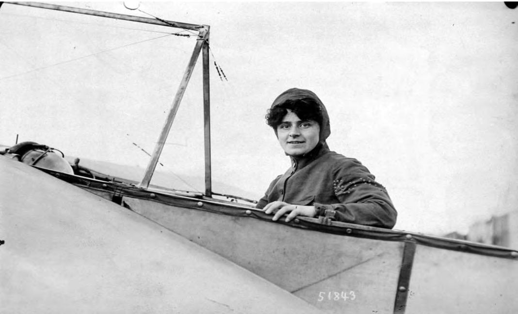
Iblame it all on Edith. Who? You know, Edith Maud Cook, the first British woman to fly an aircraft (January 1910). It was a Bleriot XI, very similar to the one in which Louis Bleriot crossed the Channel in 1909, other than the shape of the rudder. Edith was born in Ipswich on the 1 September 1878 and was unfortunately killed only months after her Bleriot flights, following a parachute accident on the 14 July 1910. I am a member of the Suffolk Aviation Heritage
Museum near Ipswich and having had a long time interest in Edith, we had previously arranged for a Blue Plaque to be placed on the house in Ipswich where she was born, and to have a headstone erected on her previously unmarked grave. So, one day, members were talking about how nice it would be if we could arrange to have an Edith Cook
Memorial Hall at the museum, perhaps even a replica
Bleriot XI. Research soon showed that the cost to have one built was far beyond our means, in the region of £12,000. This is when I said that I would build one. In retrospect, this was perhaps somewhat rash as, at that time, I had no plans or technical drawings of a Bleriot, no experience in building one, no materials, nowhere to build it and no budget! What could possibly go wrong…?! I decided straight away that if I was going to the trouble of building the Bleriot, I may as well find a set of plans for a flyable aircraft and build it as if it were going to fly, even though it would be for static display only. Unfortunately, my flying days are behind me with 1,000-plus hours mostly on Tiger Moths, Austers and Luton Minors. That was in the ‘good old days’ when you did not need a radio to fly into airfields like Stansted or Brussels International, petrol was two shillings (10p) a gallon, and few airfields charged landing fees.
Above Edith Cook First British woman to fly an aircraft.
The search for materials and sponsors
to pay for them, unfortunately at a cost beyond our means. Having tried various places in the UK without much success, I looked to the USA, but again without success. Not wishing to give up, I tried Europe and – bingo! I found the Spanish Air Museum. The Fundacion Aerea De La Comunuida Velenciana (FACV) had built a flyable Bleriot XI to the original drawings, and not only were they willing to let me have plans for the aircraft, they also provided a number of templates for various parts, in addition to a pair of main wheels – and all for free. I was also introduced to the gentleman who had built the aircraft, Señor Joan Bloomer, who also worked as an engineering volunteer at Duxford. His advice was invaluable throughout the build. Next step was, where do I get the wood? As it was non-flying, I did not have the restraints of finding approved wood, although I do not think either Louis Bleriot or Raymond Saulnier, who collaborated with Bleriot on his aircraft and went on to found Morane-Saulnier, had any concerns about wood approval. I decided to go for Douglas fir for the fuselage and main spars, and Birch plywood for the ribs. Douglas fir is nice and straight, easy to work and, importantly, has few knots. I struck lucky at the first joinery company I approached, Sunningdale Joinery (now 1st Stop Joinery) of Ipswich. Astonished at this request for a sizeable amount of wood to build an aircraft, the manager, Tony Wallis, said he would like to build it with me. I asked if I could make use of their premises to build the aircraft and he allowed it on Saturdays and in areas that did not interfere with Joinery’s work. And of course, the wood was also offered free of charge. I now had plans, wood and a place to build it. When you look at the Bleriot you will notice that it is held together by lots of U bolts and yards of 2mm stainless steel wire and turnbuckles. Where do you find wire and turnbuckles? A ship’s chandlery, maybe, but it would be very expensive. So, I tried a number of manufacturers and suppliers of marine rigging wire. James Arrowsmith, the CEO of the S3i Group of Harworth, turned out to be a fellow pilot and kindly agreed to donate the wire and the turnbuckles. And so the story of generous sponsors continues. Technology Suppliers Ltd of Shrewsbury kindly donated the 1,500mm x 4mm rods needed (16 of them) for 80-odd U bolts; Tracy Tools of Torquay freely offered advice and generously donated a number of engineering dies. And Gripfixings of Ipswich donated all of the nuts, bolts, washers that were required. We had decided on a high-quality 4mm Birch plywood for the tailplane and wing ribs and this time we had to buy four 8 x 4ft sheets at a cost of £97. However, Gliders and Racing Models Ltd of Newark kindly gave us a discount on the 1mm plywood for the leading edge of the wings, leaving us just £64 to pay. You will see from the photos that the undercarriage is of a quite simple design of steel tubes, bolted or welded together, which we thought that, with help, we could manage to make ourselves. That was before we discovered that if we wished to buy even a small piece of tube, of say 25cm in length, we had to buy three-metre lengths. I approached one company which said they could make the undercarriage, but it would take quite a time and cost hundreds of pounds. Then I remembered that a company in Ipswich called Ransomes Jacobsen Ltd, built aircraft in 1918. So I approached them to see if they would like to help in the build of another one, albeit 100 years later? The MD at the time, Alan Prickett, agreed they would build the undercarriage for us free of charge! We were now ready to build the 1910 version of the Bleriot XI as flown by Edith Maud Cook.
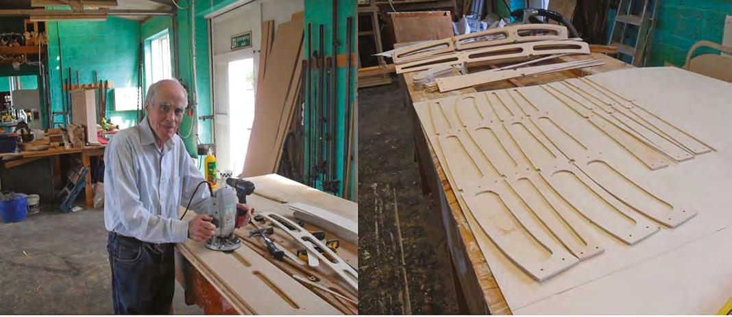
Above Telford Thomson at work on the Bleriot, having managed to gather a plethora of generous sponsors to support the building of the Bleriot.
The construction
built one will know that, unless you have ideal facilities and time on your hands, if you say six months that will usually equate to six years. We said one year, and it took just over 18 months, our main restraint being the time that was available to us at the workshop. Tony and I now had the plans and most of the materials, but where do you start? The plans were written in Spanish, German and English with metric and Imperial measurements. It was decided that we would start with the ribs for both the tailplane and the wings.
Tailplane, elevator and wing ribs
There are a total of 16 ribs in the tailplane and elevator, although fortunately they are all of the same size. Using a band saw, we cut out 16 blanks of 4mm ply and stacked them together in two bundles of eight. Then a number 3mm holes were drilled for dowels that would hold the blanks together for cutting, and also to line up with the positioning pins on the gluing jig. Then, using the template drawing, the outline of the rib was marked on the top rib blank and the band saw used to cut out the shape. Then 10 lightening holes of 30mm were drilled and 20mm x 35mm holes cut out for the two spars. A further 35mm hole was cut into the ribs to accommodate the tube for attachment of the elevators. The 24 wing ribs are also made of 4mm Birch ply in a similar manner, but due to their size they were made in three different sections. The wing ribs are in three sizes, 20 are 2,040mm in length and 850mm wide, and on four ribs (two each wingtip), the rear section is made to measure on the job.
Capstrips
Capstrips for both tailplane and wing ribs are 3mm x 20mm x 2,060mm and were placed in a steam box made from a plastic drainpipe and a wallpaper steam stripper. Pegs were placed across the width of the pipe for the strips to lay on to reduce the chance of them being contaminated from water in the pipe. A drain hole was placed in the rear end of the pipe and a steam vent on the top surface. The strips were steamed for one hour, removed and placed on a curved jig and left in place for 12 hours. Assembling the ribs was fairly straightforward, although care has to be taken not to snap the upper capstrip due to the sharp curve on the leading edge of the wing rib. I allowed a 15cm overlap at the leading edge, which was reduced when the capstrip was clamped in place (we needed a lot of clamps).
Wing spars
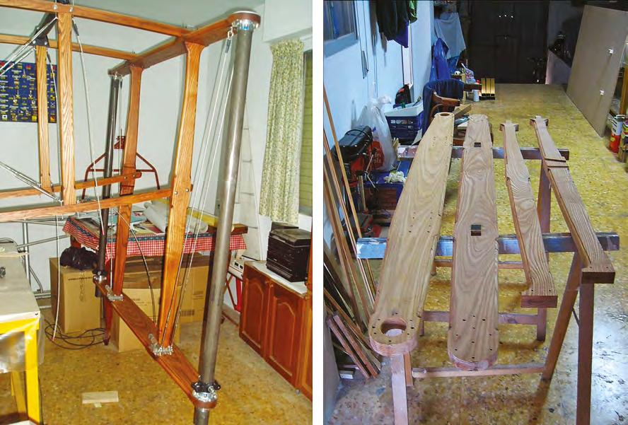
The 4125mm long wing spars were made from Douglas fir, the front spar is 19mm thick x 100mm wide with a 15˚ taper on the top and bottom edges of the spar to allow for the curvature in the wing rib. The rear spar is 16mm x 63mm with a five-degree taper. There are a further 14 (seven each wing) mini spars, 4125mm x 20 x 10mm threaded through the groves in the wing ribs. Top left Wing ribs showing the dowel pins. Photo: FACV
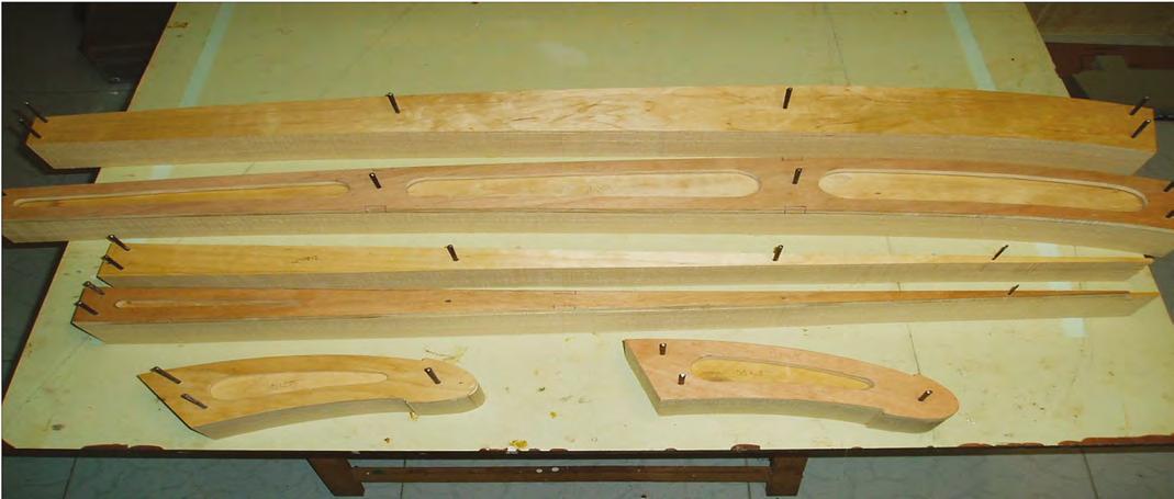
Bottom left Rear fuselage showing U bolt fittings, mortis holes and the fashioning on the crossmembers. The fuselage
Building the fuselage was also straightforward. The only problem is its length, 8.5m. Using a bench saw we cut eight lengths of 3.5m x 35mm x 35mm from a plank of Douglas fir then, using a suitable thicknesser, we planed the longerons 30mm x 30mm in a matter of minutes. Next were the fuselage crossmembers, 40 in number 80mm x 30mm x 40cm, which would later have to be fashioned and cut to the exact size. Remember, there are no glue joints on the fuselage, thus the crossmembers have to be carefully cut to allow for the taper in the fuselage shape. Each one would then need a hole mortised at either end to accommodate the U bolts. As they all look the same, it is important to mark each piece with its position on the fuselage, and which way is up. We had a slight problem when we tried to marry the front fuselage to the rear, we found that the front section was four inches wider. What had happened was, due to our restricted use of space, we had fashioned the front and rear fuselage sections in different rooms and had misread the crossmember length – we took 2. 0 ³/8in for 20 ³/ in, when in fact it was two feet and ³/88 of an inch. We had also drilled the U bolt holes in the longerons before steaming and bending them on the jig – big mistake – when bent to fit the jig, two of the longerons snapped at the holes. Something else we discovered was not to pre-drill the holes for the mounting bolts between the longeron and the main undercarriage struts – the bed posts. First fit them into position, clamp them together and then drill through both structures. What is it they say about your second aircraft being built much more quickly than the first!
The bedposts
Fortunately, we had templates for this important structure, which is the mounting for both the main undercarriage and the engine. Using a bench saw, we cut four planks to slightly larger size than needed, then ran them through the thicknesser. Next, we placed the template over the planks and cut them to size, marking the positions for the mounting holes. The bedpost structure is fastened together by a number of 90˚ metal brackets. We were also lucky here as we had 1:1 scale drawings for each bracket.
Assembling the fuselage
The fuselage can be built in two sections with the longerons spliced and bolted together, or in one large structure with the longerons spliced and glued together. We were not going to fly the aircraft, so we went for a bolted splice. We found it was best to attach the vertical and lateral crossmembers to only one side of the fuselage and then, when all were in place, bring both sides together. You need a few spare hands for this. The U bolt arms needed to be made about 4cm longer than the finished size and were laced through the mortis on the strut and then through the holes in longeron. You can use the U bolts to tighten the rigging, instead of
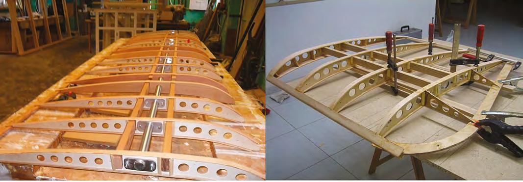
Left The bed posts with the undercarriage tubes in place. Photo: FACV
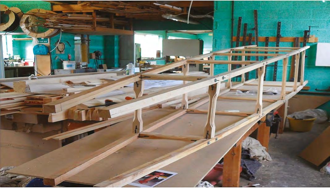
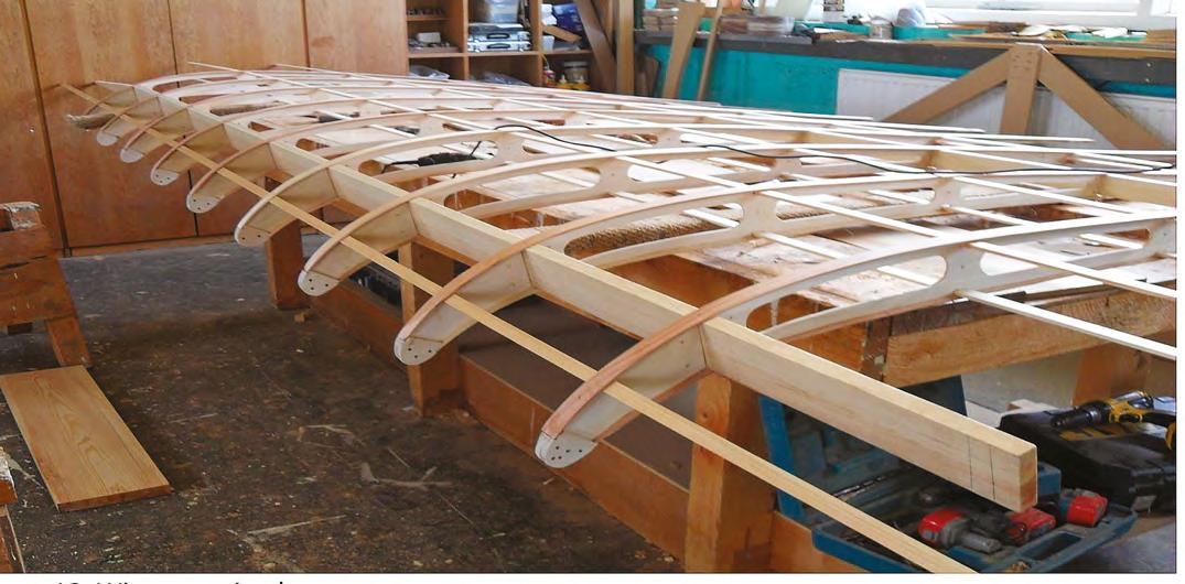
Below One of the wings makes good progress. They proved quite straightforward to construct.
Bottom The tailplane structure. The elevators pivot off each end rather that off the back of the tailplane.
turnbuckles, and then cut the U bolt arms to the correct length once the rigging wires are attached. We also discovered that before reducing the size of the U bolts you have to check, and check again (!) that the spars are in the correct position, not upside down etc. because you will find that you almost have to disassemble the whole fuselage to get one out if it is in wrong. Don’t ask! Now we come to the fun part – attaching the bedposts. Life is easier if you have the metal brackets for the attachment of the vertical and lateral crossmembers fitted in place, as well as both metal tubes for the undercarriage, which will be positioned between, and attached to, the lateral arms of the bedposts. If you do not have the tubes, you can still attach the bedposts, but you will have to turn the fuselage upside down – as the tubes only go through the bottom lateral strut.
Attaching the bedposts and undercarriage
When it comes to attaching the bedposts, you will find out why you should not pre-drill the bolt holes. Holding the bedposts in position and then sliding the upper longerons over the top lateral spar and the bottom longerons on the inside of the vertical post, the bedposts are not at 90˚ but at a slight slope (we could not find a measurement for this on the drawings). This is due to the curvature of the longerons. So, once all clamped up, we drill the holes. All we had to do then was fit the floor of the cockpit and the crash protection around the edge of the cockpit, install the pilot’s seat and rudder bar and tighten the fuselage wires – and it was all done. If you had all the parts ready, three people could assemble the fuselage in a matter of a few hours.
The wings
Once all parts were cut to size, we experienced no problems in putting them together. We placed the main spars on a trestle high enough to allow for the curvature of the leading edge, this was placed on a table then the completed ribs were slid in place. With the ribs in position it is then possible to fit the mini struts as well as the trailing edge. Before gluing we then placed spacers between each rib to ensure everything was at 90˚ and the correct distance apart. Next, we positioned and glued the tension plates in position between the top and bottom mini spars. The trailing edge section on the wingtip ribs numbers 11 and 12 were then cut to size and the wingtip edging glued in place.
The tailplane and elevators and rudder
Building the tailplane and elevator was straightforward, they are just a mini version of the wing. We built ours with full width elevators at either end of the tailplane. The rudder too was uncomplicated. We drew the trailing edge outline on a sheet of 4mm ply and cut it to size, then attached the bracing struts, and metal fittings. We covered the rudder in a cotton bedsheet, applied the dope and then stitched in place. It looks authentic. It is just too expensive to cover in aircraft fabric.
Below The Bleriot XI on display at the Suffolk Aviation Heritage Museum (Ipswich). Attaching the wings
Four people were needed for this, one standing in the cockpit to attach the bracing wires (four each wing) to the metal ‘bird cage’ above the cockpit. Another guided the front spar into the wing mounts, which was resting on top of the fuselage, and two others took the weight of the wings. Another discovery was that if you stand back admiring your work with only one wing on, and nobody supporting it, the aircraft will tip over, undoing all your good work! With both wings fitted and the supporting rigging wires at the correct tension, we fitted the wing warping wires (two each wing) to the warping arm, which is fitted on a metal structure under the fuselage. Two further wires per wing are attached to the lower fitting on the bedposts. The Bleriot XI turned out to be simple aircraft to build, provided you have the correct woodworking tools and the engineering facility to make the undercarriage, and a large room with a door high enough to get the fuselage through – with the upper wing rigging mount in place it is 8ft in height. Tony and I were fortunate in that we had full-size templates and most of the plans were 1/1 scale – and the invaluable advice given by Señor Bloomer. We also had help from Colin Durrant, the chairman of the Museum, and Paddy and Tom from 1st Stop Joinery. Our thanks too to all our generous sponsors, without whom this project would not have been possible. The aircraft is now on display in the Suffolk Aviation Heritage Museum, Foxhall Road, Ipswich. ■


