8 minute read
Engineering Matters


Including: Rotax carburettor float guide checking, failures with bracing wires and inaccurate analogue gauges. Got a submission? Send it to
engineering@laa.uk.com
Rotax 912 carburettor float guides
Problems with the floats fitted to Rotax 91x Series engines over the years are well documented, but what may be a new issue has recently come to light on a BMAA-administered EuroFox.
The new owner of the aircraft discovered it was suffering from starting and running difficulties, which were more than likely there at the time of the sale.
LAA Inspector, Ian Daniels, was asked to have a look, and having gone through the basic inspection items, removed the float bowls to check the floats, as well as for any other issues. One of the floats was found to have a loose brass guide tube which was effectively free to slide in and out of the float, although at times, it would stay put. Wear marks indicated that the guide tube had been moving for some time. One of the holes for the guide tube in the float was round but the other was oval.
CFS, the UK Rotax distributor, replaced the floats under warranty. It would be wise to check the security of the guide tubes whenever
A Pitts Special on the LAA fleet was found, after landing, to have a broken tailplane upper bracing wire. The wire was reported by the pilot as being intact with good tension before flight and the break only noticed after landing and parking. A maximum of 4g was pulled during the flight, and no ill effect on handling was felt.
In discussion with Pitts Specials experts, it would appear that failures of tail brace wire have happened many times before, and to the best of their knowledge have not resulted in any major issue in flight. That said, there remains the possibility that there is potential for it causing a problem if the aircraft was manoeuvred harshly after a wire failure occurs.
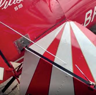
An excellent source of reference regarding streamline wires including their installation, inspection and upkeep is the de Havilland Support Ltd Moth Aircraft Technical News Sheet CT (MOTH) No 23.
Lexan and windows
Inspector Ray Harper reports that he has recently seen yet another high-wing aircraft with wing tanks and a Lexan windsceen that has been damaged by a fuel spill during refuelling.
Ray mentioned that he is aware that some manufacturers (such as Murphy) moved away from Lexan for this reason.
It isn’t just high-wing aircraft where there is a potential issue. The original RV-12 rear window was Lexan and we always protected ours during refuelling operations with a rubber mat as the refuelling point was only just aft of the rear window. Later RV-12s use a Perspex rear window and the refuelling point is now lower down on the fuselage side.
Tool checks
Ballistic Parachute Recovery Systems: CAA G-INFO and LAA ‘My Data’
As mentioned previously, the CAA G-INFO entry for an aircraft should now show if it has a Ballistic Parachute Recovery System fitted. This is to assist first responders if they are attending an aircraft incident.
If your aircraft has a BPRS fitted, please visit G-INFO and check that the details for your aircraft are correct. Please notify LAA Engineering if G-INFO is showing incorrect information.
Similarly, LAA members can log onto the LAA website and check their aircraft details under ‘My Data’. Please advise LAA Engineering if there are any errors.
Control locks
A well-publicised incident in the USA that occurred in July 2021, resulted in the death of a highly experienced airshow pilot who was also an ex-US Navy aviator. The NTSB discovered in the course of its investigation that, in all probability, the control lock had not been removed prior to departure.
The control lock on the aircraft in question (a tandem two-seater) was floor mounted and secured the P1 control column, but allowed the normal rudder pedal and tailwheel movement.

If a control lock is fitted, then ideally this should secure the P1 controls to give the best chance of it not being overlooked during the pre-flight checks. The incident in question demonstrates that even then, for whatever reason, the control lock may still be missed.
The safest types of lock are those that actually prevent the pilot taking their seat unless the control lock has been removed.
Factory-built gyro modifications
It has become apparent that some factory-built gyros (FBG) may have been modified in the field without following the correct procedures for the type.
While it is possible to apply for a modification via LAA Engineering for those FBG that are administered by the LAA, the ‘LAA Standard Mods’ should not be embodied on FBGs in the same manner to which they are on other applicable LAA-administered types.
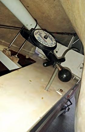
We received an email from seasoned LAA Inspector, Phil Chapman, who was taking advantage of the warm weather to check the stabilator control cable tensions of his Jodel.
At the end of the day, with the maintenance tasks complete and having refitted the large empennage fairing, Phil could not locate the tensiometer.
On lifting one side of the fairing and using his phone camera to look inside – mystery solved.
VW Revmaster pushrod
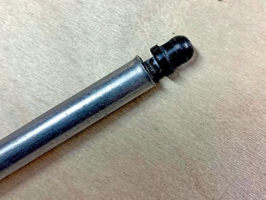
While completing a valve clearance check on his VW-based Revmaster R2300 engine, Richard Teverson found that one valve had an excessive tappet clearance of nearly 1/8in.
On closer examination the steel inserted end of the aluminium pushrod had come loose and hammered the aluminium tube. If this had not been noticed in time, the pushrod could have failed completely.
Richard reports that he contacted Joe Horvath at Revmaster who advised to replace all the aluminium pushrods with steel ones. Apparently, it is possible to purchase them in the UK from Aircooled Hut UK Ltd.


Many years ago, Lycoming introduced a ‘production improvement’ for the O-235 series engines which are one of the few Lycoming engine models that do not utilise hydraulic tappets.
This improvement was to replace the aluminium pushrods with steel versions. As part of this change, the dry tappet clearance was reduced from 0.010in to 0.005in as the steel pushrods would expand less than the aluminium ones at working temperature. The engine data plate had to be restamped for the new clearance figure.
Wing damage? Additional inspection points

When an aircraft is involved in a collision, be it in the air, on the ground, with something moving or stationary, it is imperative that a thorough inspection is carried out to ensure that no damage has occurred to the surrounding structure.

Additionally, areas further away from the initial contact point must be accessed and inspected for damage. Examples of this are when the outboard section of a wing strikes something other than the air.


Wings are carefully designed to provide strength in specific directions, reacting against certain loads. They do not take kindly, for instance, to a fore or aft load. With a leading edge striking an object, because of the long lever arms involved, there is every chance that damage has been caused to the wing attachment points, especially the rear spar. Not only is it the spars that are at risk but also the fuselage structure to which they attach and the same for aircraft with wing struts.
As part of the repair process for aircraft involved in such incidents, rigging checks should be carried out before and after the repairs to ensure the airframe is in alignment and entries made in the worksheets confirming the inspections to the airframe structure and the rigging check have been carried out.
Accuracy of analogue instruments
LAA aircraft owner, Angus Fleming, was surprised to discover just how inaccurate engine gauges may be when compared to modern EFIS electronic systems.
Angus compared his Rotax tachometer with a calibrated TruTach optical digital tachometer. The difference was an underread of the Rotax instrument of up to 9%, which could easily result in an
LAA Engineering housekeeping
unknown engine overspeed situation. Even electronic gauges may not be accurate and the old-style ‘magnet and cup’ car speedometers will probably be the worst of all. Most people accept that car speedometers may be up to 10% inaccurate and the same ‘technology’ is used in cable driven aircraft tachos. Of course, the same issues can affect other
Emails going to spam For reasons best known to someone else, there appears to be a higher than normal proportion of emails sent from LAA Engineering that are going straight into recipients’ Spam or Junk folders.
If you are expecting an email from LAA Engineering and it has not appeared, please check your Spam or Junk folder.
Patience please We are currently in the busiest period of the year in LAA Engineering, please be patient if your query, Permit to Fly revalidation, repair or modification is not dealt with as quickly as you might hope.
Postage charges We receive two or three items of delayed post a week due to insufficient postage.
The way the Royal Mail system works means these items go off on a different route and can take two weeks to arrive at LAA HQ. Currently, LAA absorb the associated ‘fines’ but in the future may have to claim the money back from the sender.
LAA Engineering charges
Initial Permit issue Up to 450kg £450
Permit Revalidation now be paid online via LAA Shop) Up to 450kg
1,000kg and above £260
Factory-built gyroplanes* (all weights) £275
*Gyros note: if the last Renewal wasn’t administered by the LAA, an extra fee of £125 applies
Modification application
Prototype modification minimum £60
Repeat modification minimum £30 Transfer (from C of A to Permit or CAA Permit to LAA Permit)
Four-seat aircraft aircraft flight and engine instruments. If in doubt check your tach reading. It may be possible to adjust or recalibrate the aircraft’s instrument, but not necessarily over the entire range.
Generally speaking, the modern ‘glass cockpit’ EFIS systems are more accurate, but should still have a check calibration wherever possible.
Europa door latch stop Mod/247/012 Permit to Fly revalidation applications are being received with no record of the mandatory modification having been carried out. The Standard Mod SM15833 LAA/MOD 1 form must be submitted to LAA Engineering before the Permit to Fly can be revalidated.
Permit to fly revalidation check flight W&B The take-off weight for the Permit to Fly revalidation check flight should be in excess of 90% of the MTWA for the aircraft, as this makes aircraft performance monitoring more meaningful.
Additionally, the centre of gravity at take-off should be within the limits stated in the aircraft’s Operating Limitations document and use the same datum as specified and please include the units of measurement, not a percentage of MAC, unless that is what is used in the Operating Limitations document.
It is surprising just how many applications are received with a centre of gravity that is outside limits and the incorrect ‘forward of datum’ or ‘aft of datum’ stated. ■
Recent Alerts & AILs
Please note the Engineering section of the LAA website has the most current information.
LAA TSB: TSB-001-2022
Applicability: All Europa aircraft
Europa: Door latch system stop
CAA MPD: 2022-003
Manufacturer’s/agent’s type acceptance fee
Project registration royalty
Category change
Group A to microlight
Microlight to Group A
Change of G-Registration fee
Issue of Permit documents following G-Reg change
Replacement Documents
Lost, stolen etc (fee is per document)£20
PLEASE NOTE: When you’re submitting documents using an A4-sized envelope, a first-class stamp is insufficient postage.
LAA AIL: MOD/247/012
LAA Alert: LAA/AWA/21/08
Note: CAA MPD 2022-003 has now been corrected as of 22 June 2022
MT-PROPELLER ENTWICKLUNG GmbH
Applicability: MTV-( ) Variable Pitch Propellers
Subject: Propeller Blade Lag Screw Replacement EASA AD 2022-0134
Note: Please see the MT Propeller TADS P17 link to the ‘EASA AD Safety Publishing Tool’ for further info.
SLING
Applicability: All Sling aircraft types and serials
Subject: Eyebolt inspection and conditional replacement Sling Service Bulletin #0020
Note: It has been found that the eyebolts fitted in the control system of certain Sling aircraft may fail to meet the manufacturer’s specification in regard to fatigue life. Such eyebolts are identifiable by the narrowness of the neck of the eyebolt above the bolt thread. This service bulletin details the procedures for inspection and replacement of such eyebolts in the various control systems.