10 minute read
3.0 Task 2 : Architectural Components

from Design by Robots

Advertisement
(2)

(4) (5)
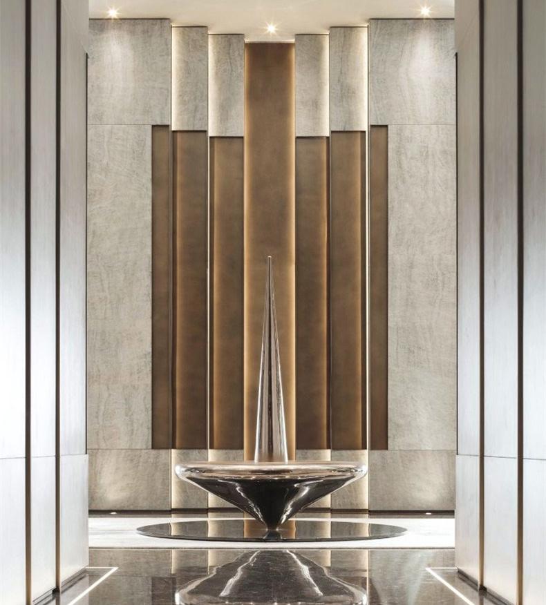
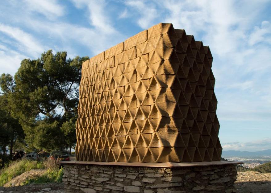
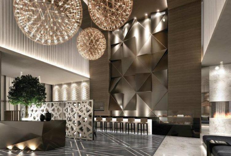
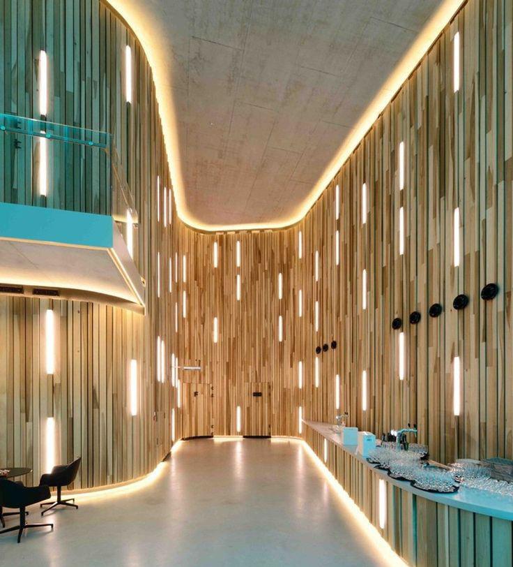
(1)-(5)Hotel Lobby - Reference Images
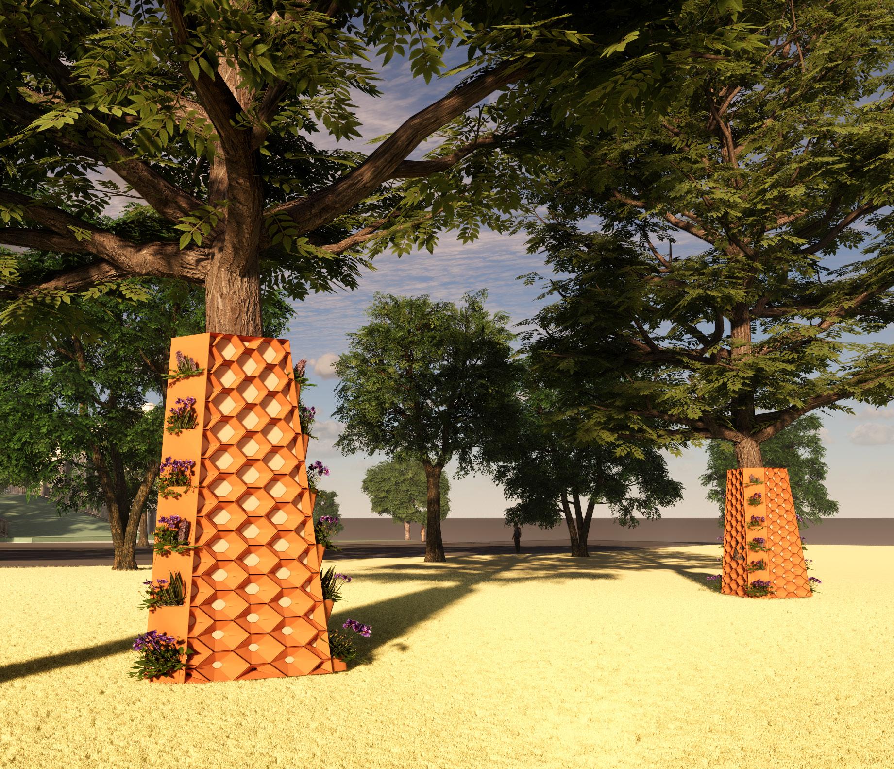
HOTEL LOBBY
Hotel lobbies are grand and always comprise of amazing lighting. Lighting constitutes as an important part of the entire setting. The most striking features of the hotel lobby is the reception wall (feature wall), a sculpture, or the backdrop of the sculpture itself.
Concept
“Find beauty in not only the thing itself but in the pattern of the shadows, the light and the dark that thing provides.”
-Junichiro Tanizaki
Ideation
The attempt was to integrate an organic form exploring potential of computational tools, understanding clay as a material (its strengths, weaknesses, textures etc.) and the light itself.
“We perceive the nature of light from the surface that receives it.”
(2)

(4) (5)

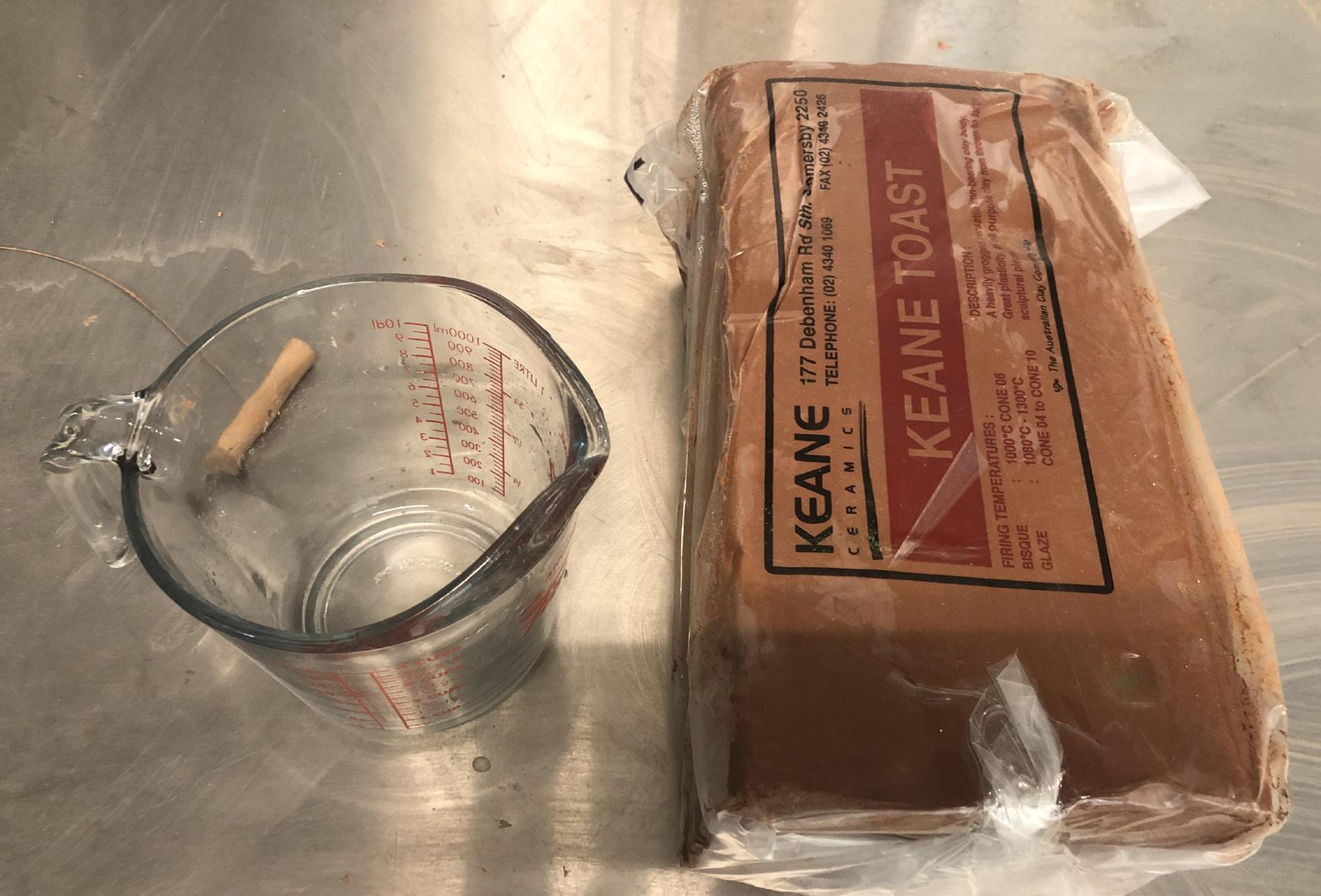
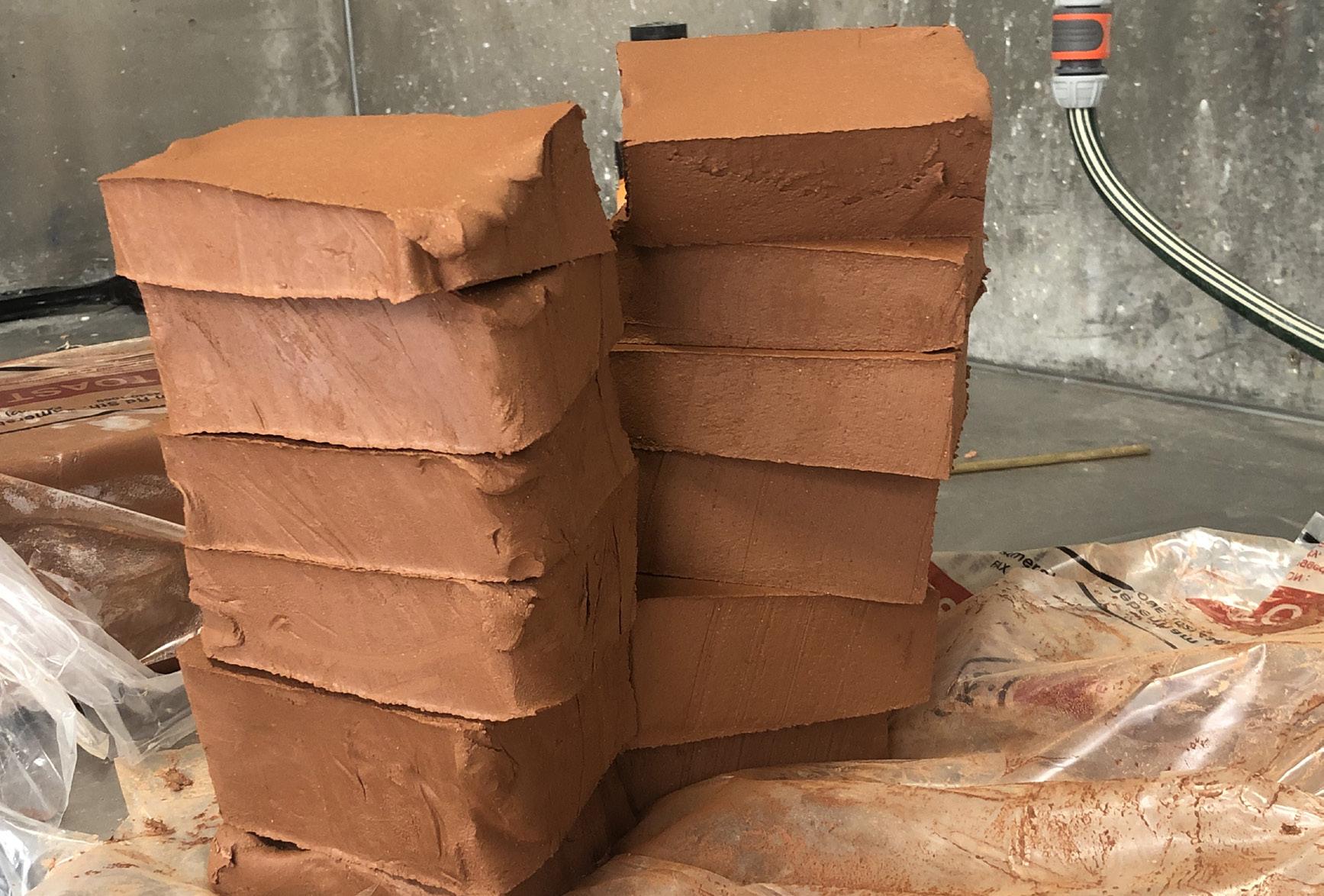
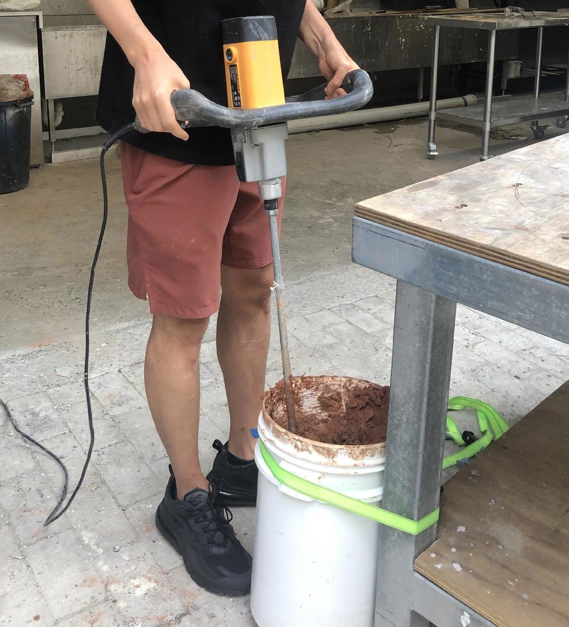
(1) Material and Equipments, (2) Clay cut in small chunks, (3) Using fastening belt, (4) Mixing the clay, (5)Filling up tube with clay
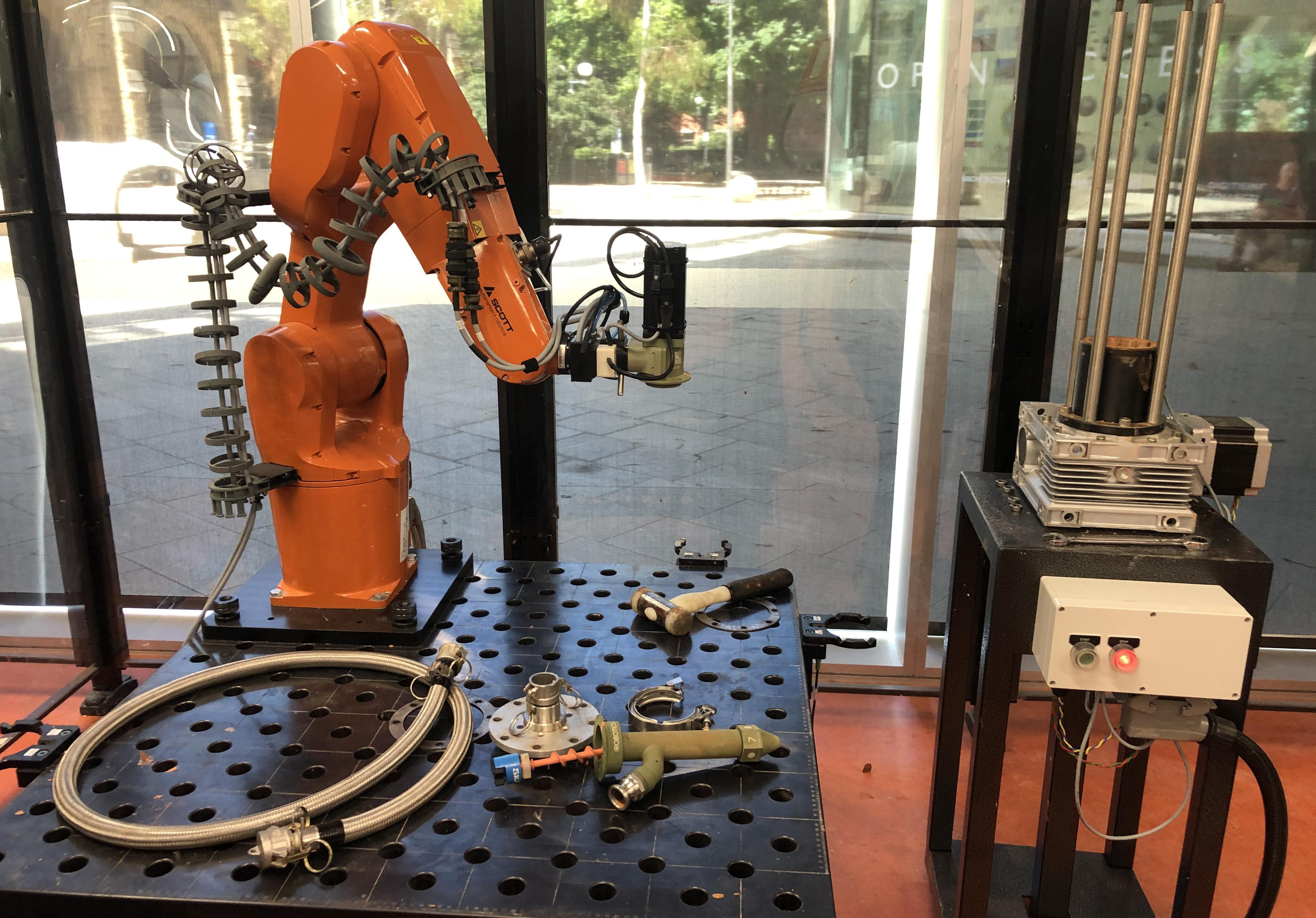
PREPARATION OF CLAY
Step 1
Arranging a beaker/jug for measuring water, a metal wire to cut the clay in pieces and one bag of clay that weighs around 12.5 kgs, a bucket to mix clay, electronic mixer and a fastening belt.
Step 2
Tying up the bucket to a stable support using fastening belt.
Step 3
Cutting the block of clay in small chunks of clay and adding 500ml of water to the clay for mixing.
Step 4
Mixing the clay using the electronic mixer until a homogenous mixture of clay is formed.
Step 5
Filling up tubes of clay for printing.

(2) Breaking down in parts
(1) Design Development : Concept 1 (3) Creating individual bricks
DESIGN DEVELOPMENT 1
The idea was to create a backdrop for a reception area in a hotel lobby.
Discussion with Ryan and Lewis
Though the walls would create shadow patterns, the idea of using light was with an external source which was not in accordance to the initial conceptual idea.
The form or the pattern of the wall was something that could be achieved using Wood and CNC machines. So what is the real need of it being 3D printed? Always think whether, there any other options that could be cheaper and question the need of being 3D printed.
Reflections
While designing we should take into consideration the real need of the object being 3D printed. The real power of 3D printing is to explore and create objects that are complex and which really need 3D printing technology for creation.

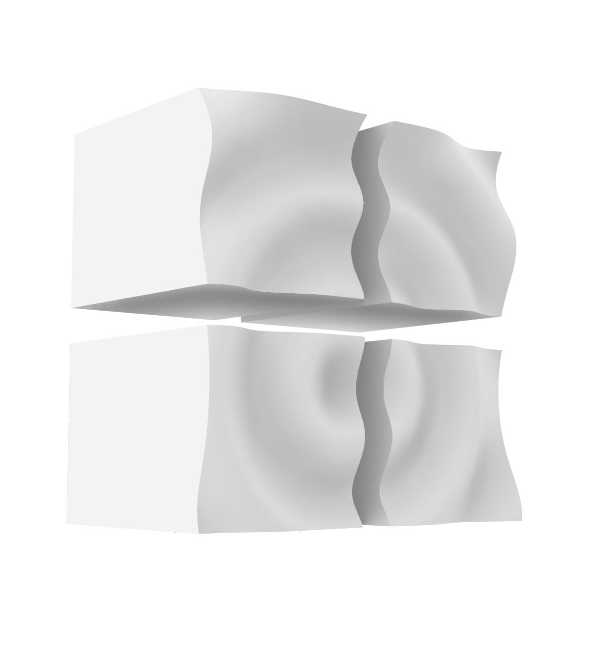
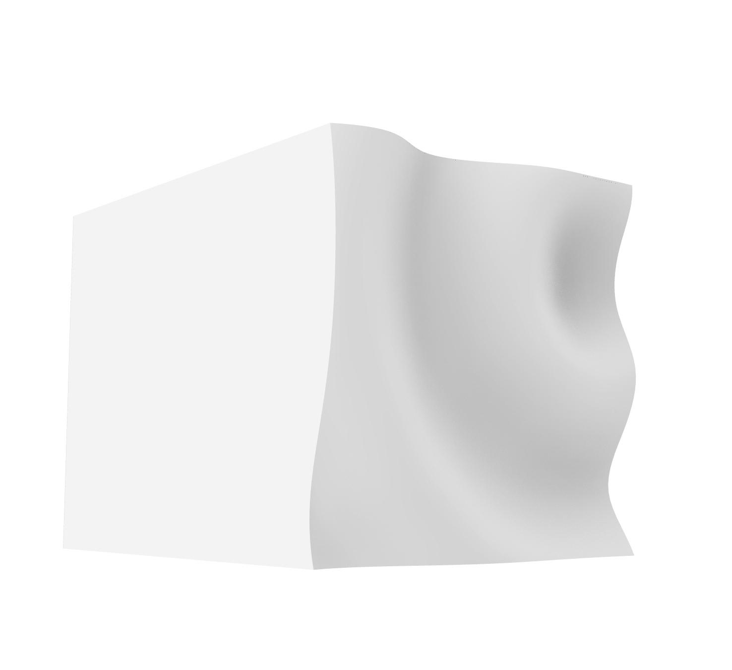
(1) Design Development 2 (2) Modular Brick : Type 1
(3) Modular Brick : Type 2
DESIGN DEVELOPMENT 2
The idea was to create a backdrop wall for a reception area or a feature wall in a hotel lobby.
Discussion with Ryan and Lewis
The wall served the purpose of being a light feature as a strong idea, but was too modular. It is like two types of bricks and multiple replications.
But the real strength of 3D printing can be explored using digital computational tools like grasshopper where each brick can be unique and less modular.
Reflections
A non-modular form can be created by printing unique bricks but having the same idea. The real power of 3D printing is to explore and create objects that are complex and which really need 3D printing technology for creation.
(2)
(4)
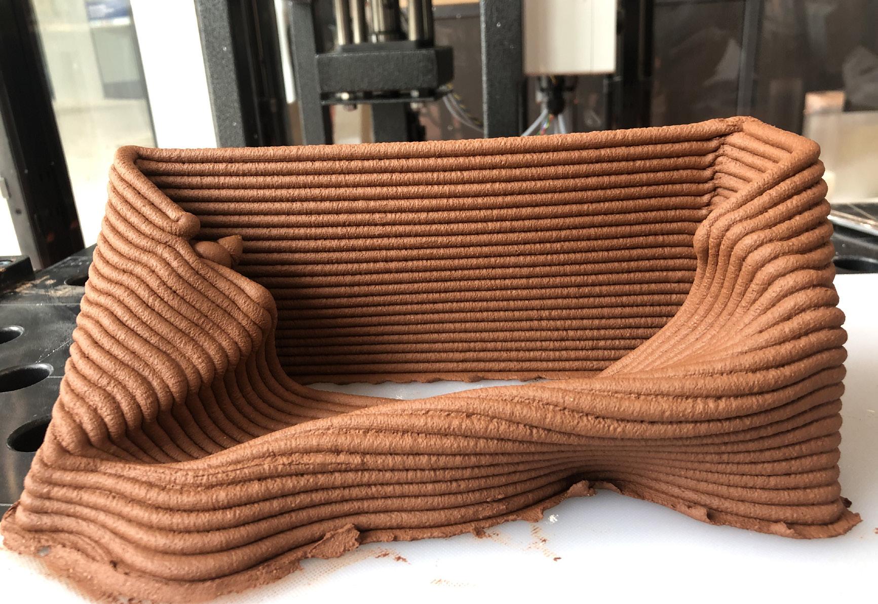
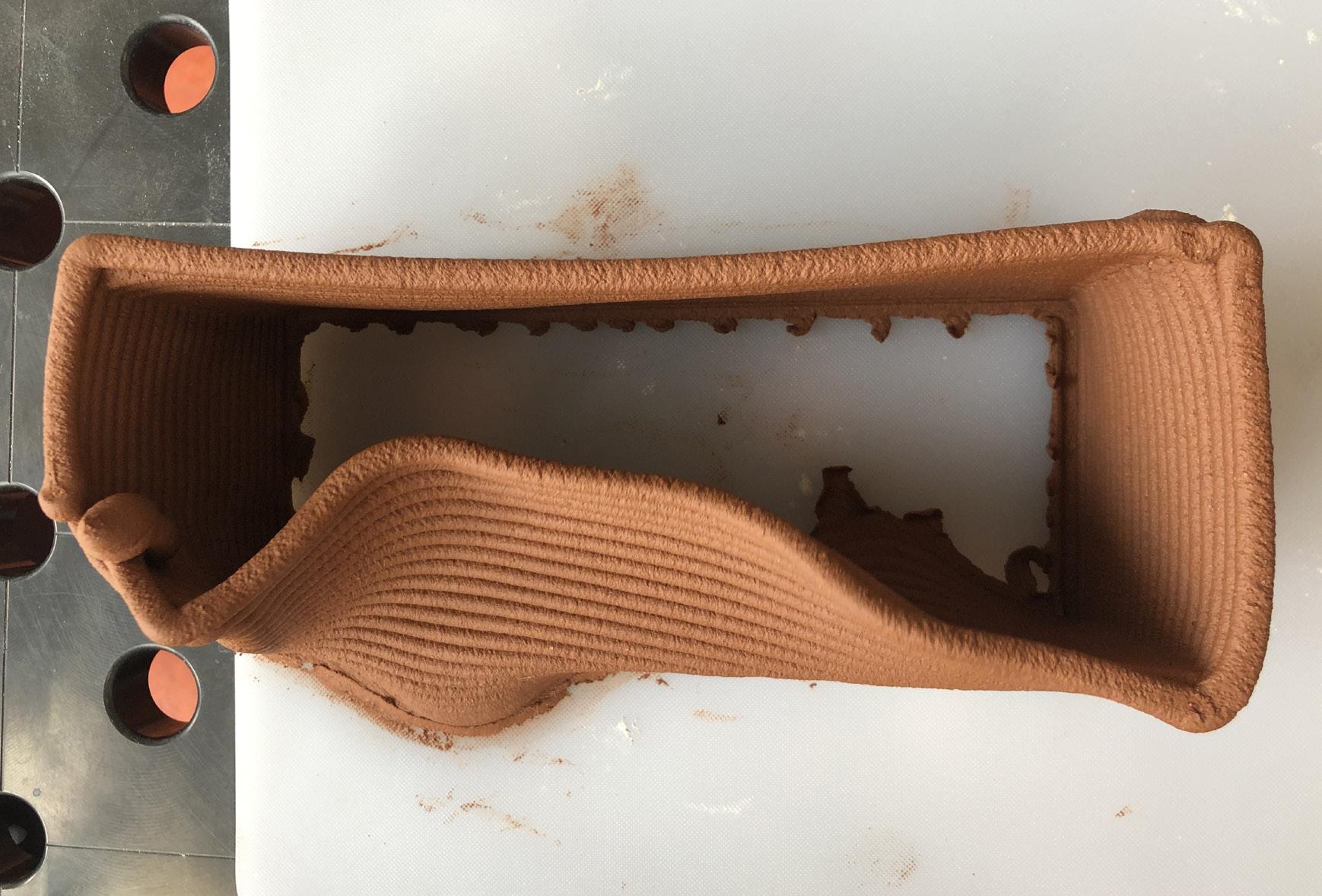
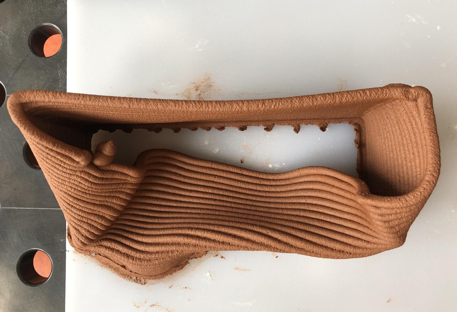
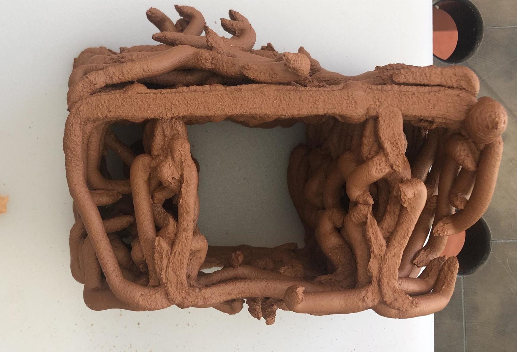
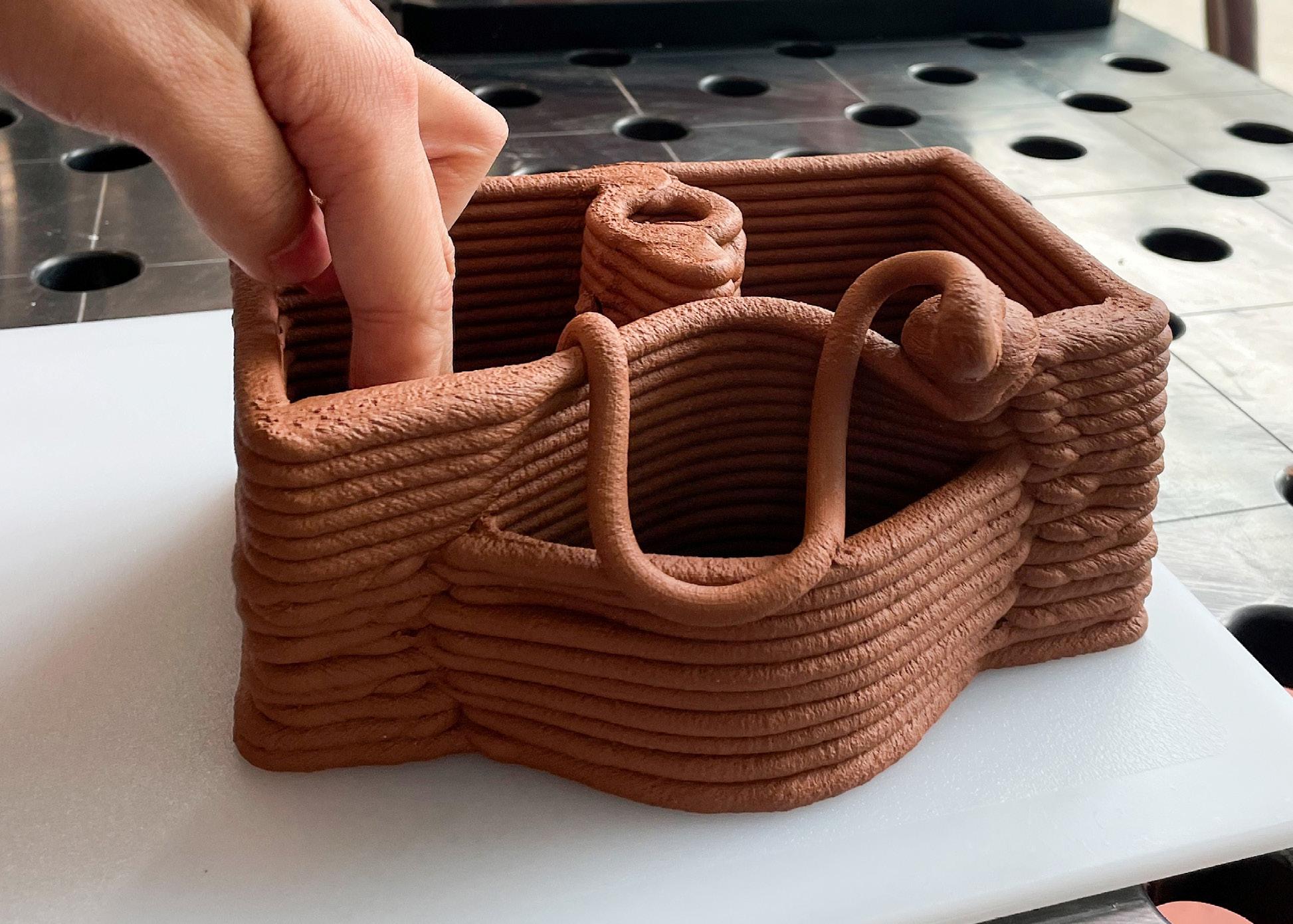
(1)Designed brick, (2)Printed Brick, (3)-(4)Brick collapsed while shifting.
BRICK TEST - 1
The brick printed well at first but then it collapsed by self weight. The bottom layer was disrupted because the height was not set up properly in grasshopper script.
Reflection
The brick needs internal supports to hold the curved surface intact. It is important to check the height from which robot starts printing on the pad. Its important to also consider the change in thickness of the surface on which the brick is printed. Such disrupted layer may create defects or cracking while firing or it way affect the joinery of bricks.

(2)

(4)
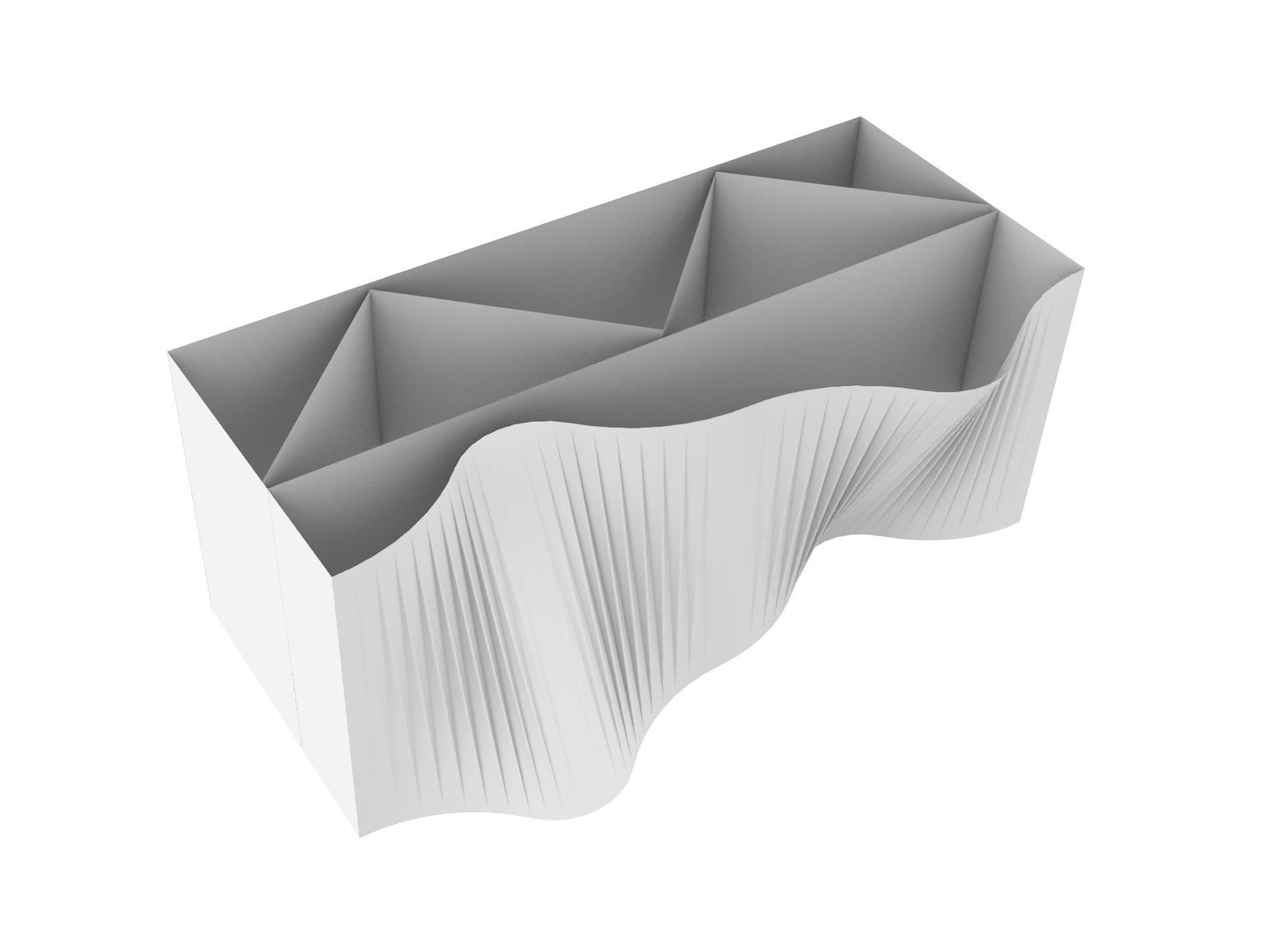
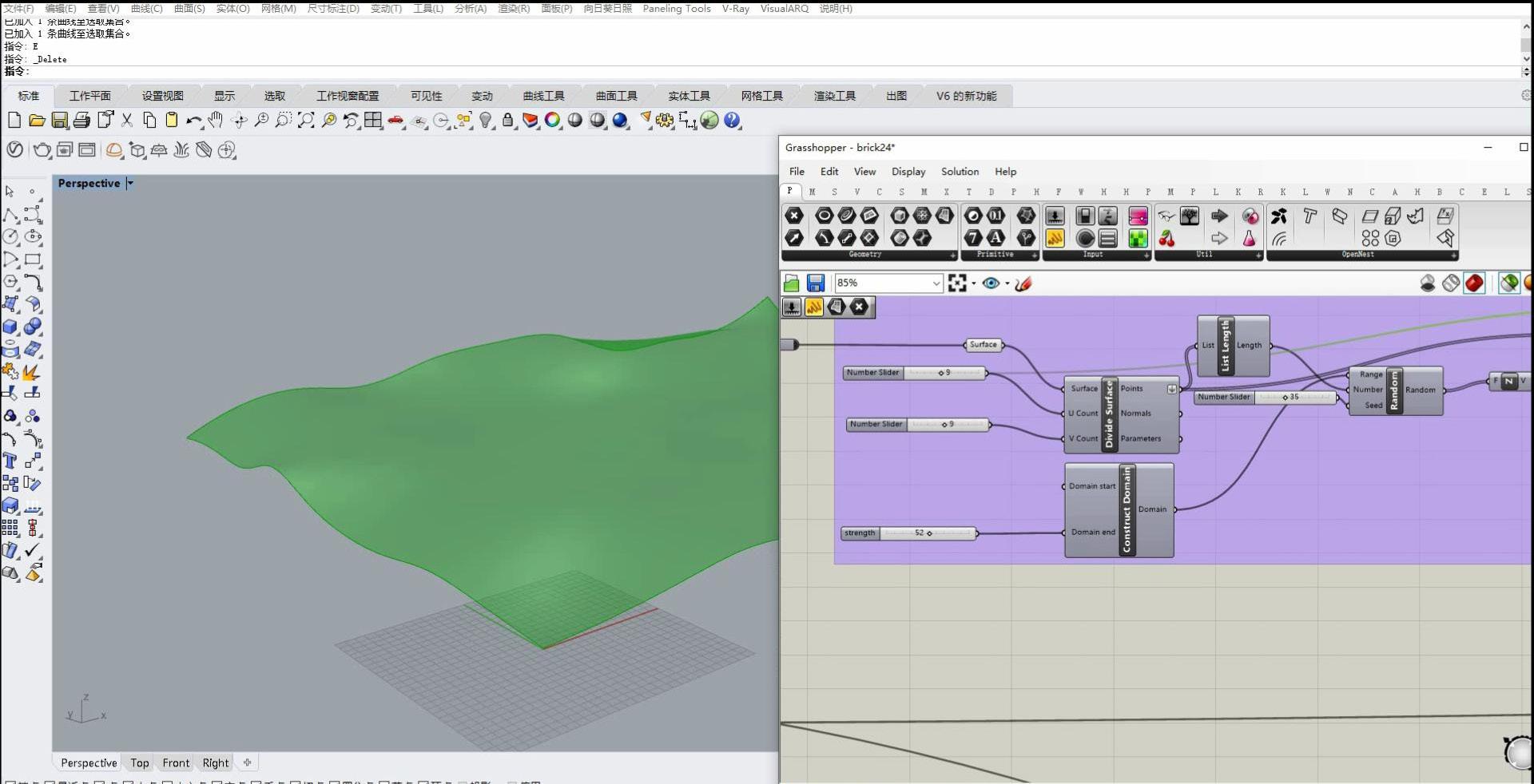
(1)Designed brick with supports, (2)Creating continuous single surface, (3)Step 3 - Upload the geometry curve in grasshopper script, (4)Script - Enable
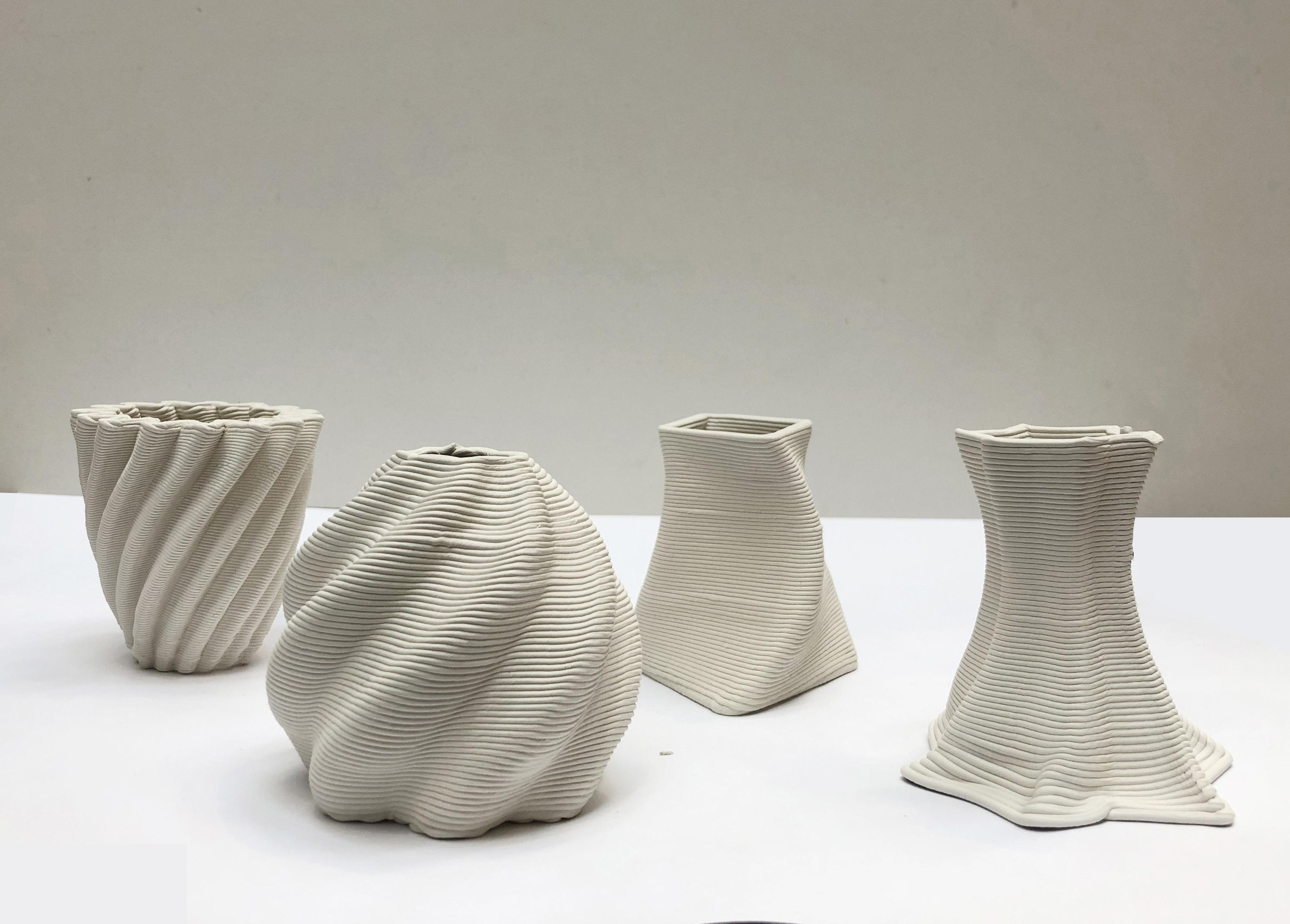
BRICK TEST - 2
Step 1
Designing the object in rhino.
Step 2
Converting the object into a continuous surface with 5mm gap between adjacent sides. (The gap will change depending on the extrusion width)
Step 3
Input the surface in to grasshopper script and change the settings to Continuous and Surface/Mesh (Refer Fig 3).
Step 4
Continuous spiral printing file is ready to be loaded in the robot to be printed.
(1) Design Development 2 (2) Modular Brick : Type 1
(3) Modular Brick : Type 2
DESIGN DEVELOPMENT 2
The idea was to create a backdrop wall for a reception area or a feature wall in a hotel lobby.
Discussion with Ryan and Lewis
The wall served the purpose of being a light feature as a strong idea, but was too modular. It is like two types of bricks and multiple replications.
But the real strength of 3D printing can be explored using digital computational tools like grasshopper where each brick can be unique and less modular.
Reflections
A non-modular form can be created by printing unique bricks but having the same idea. The real power of 3D printing is to explore and create objects that are complex and which really need 3D printing technology for creation.

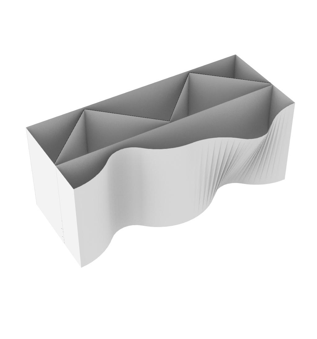
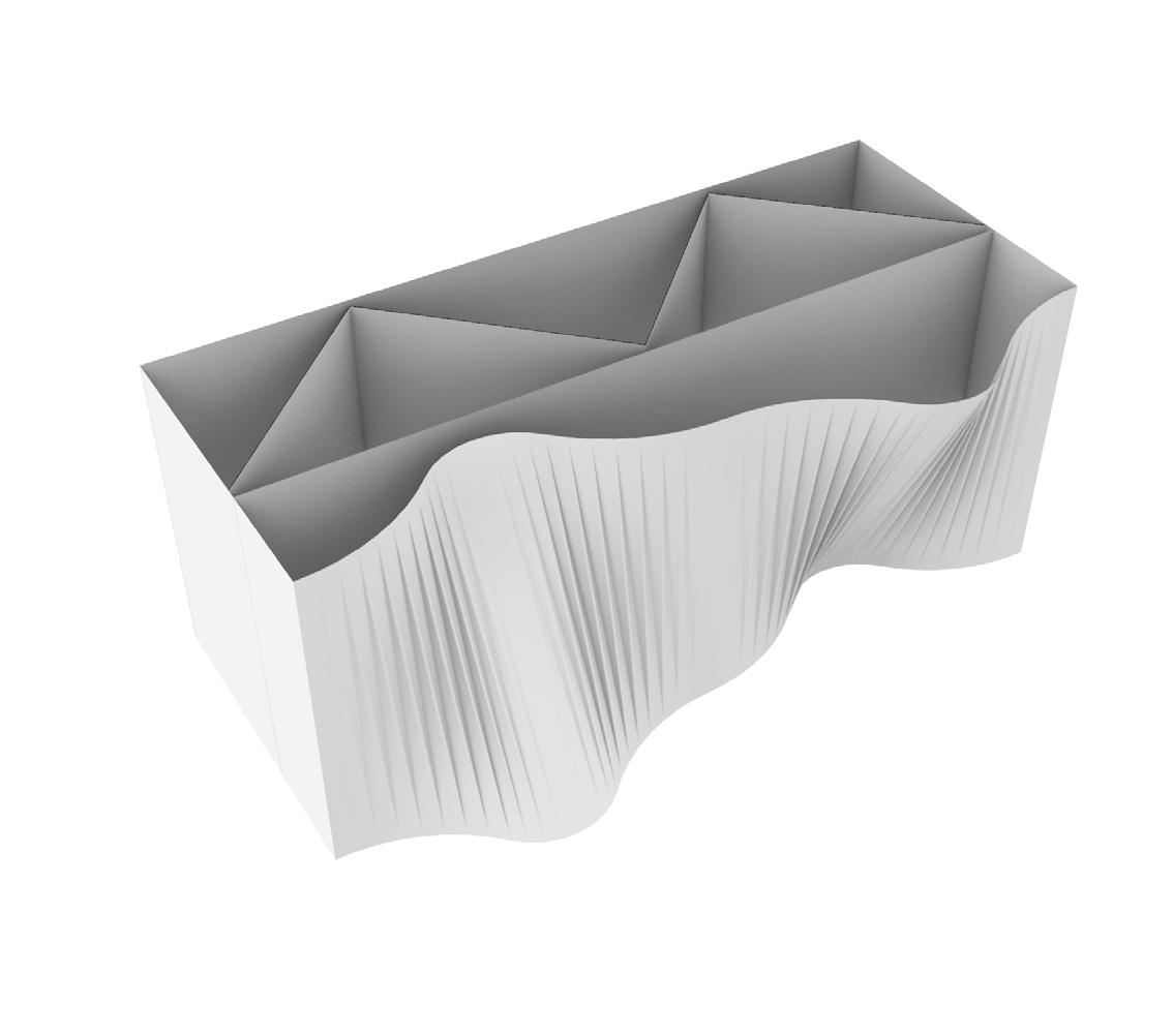
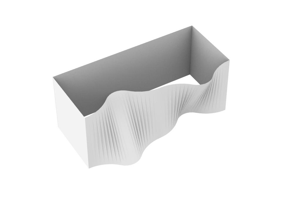
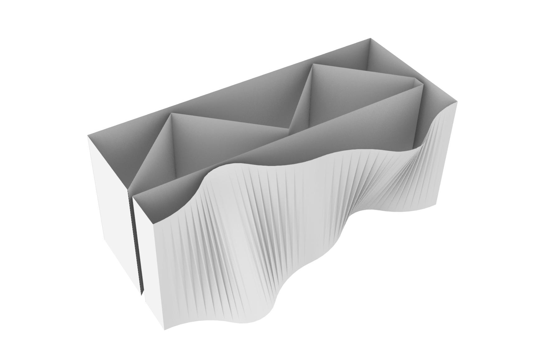
(1) Design Development 3 (2) Side Elevation
PARAMETRIC WORKFLOW Step 1: Grasshopper script used to create the base parametric surface of the wall

PARAMETRIC WORKFLOW Step 2: Grasshopper script used to create the base parametric surface of the wall

PARAMETRIC WORKFLOW Step3: Merging the base surface and the convex surfaces together

PARAMETRIC WORKFLOW Step 4: Creating bricks by developing the sides and flat rear surface
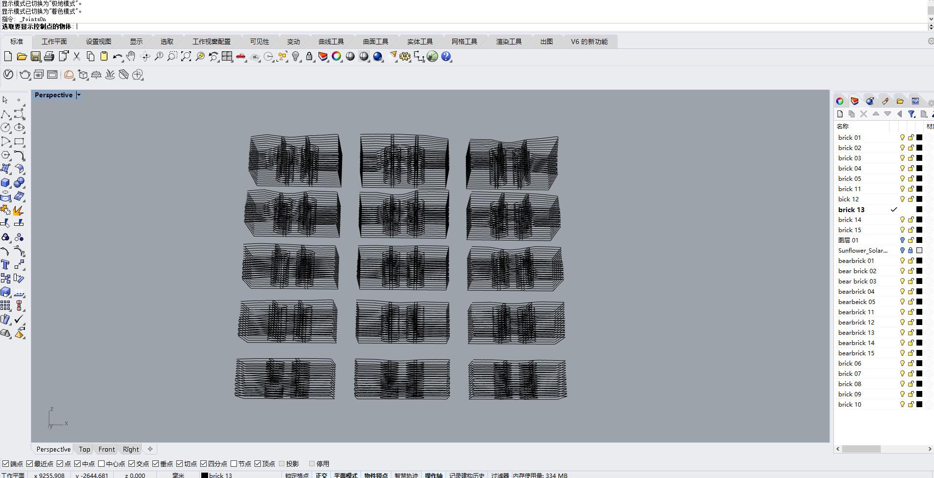
PARAMETRIC WORKFLOW Step 5: Final bricks labelled and ready to be printed


(1)Test 1, (2)Test 2, (3)Test 3, (4)Test 4 Image Source: Xiong and Shubbaam (2)

(4)
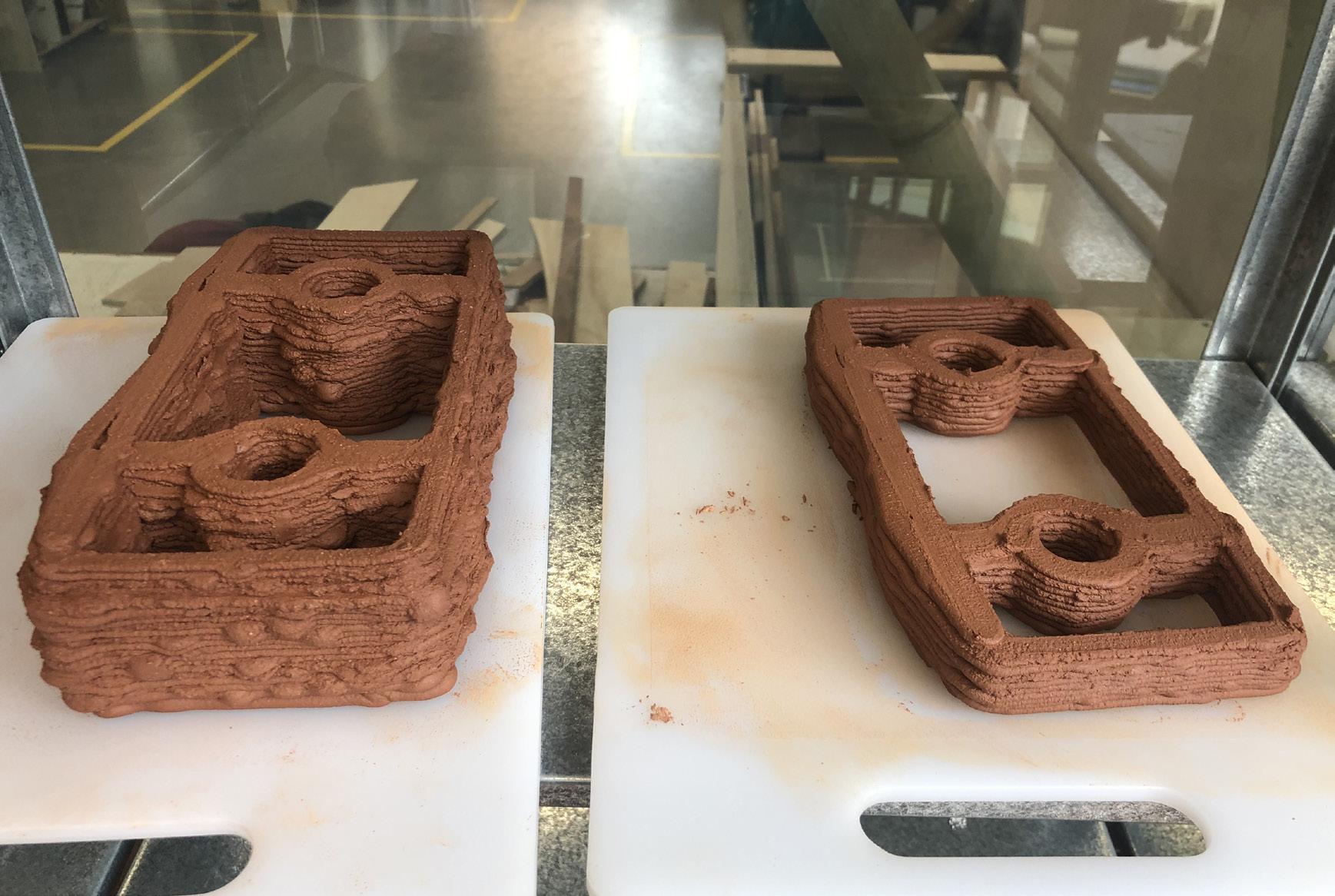
BRICK TEST PRINTING
During the print process, we encountered some problems. The first problem was deriving the relation between the speed of auger, speed of ram and printing speed to a best suitable level to print the bricks.
Various tests were done by changing the values of the above parameters. We observed that some parameters caused each layer be too thick(slow robot speed), and some parameters will cause broken lines (high speed and low auger speed) and discontinuities in the last few layers of clay.
The robotic script had a prior setting of increasing the printing speed as it printed from bottom to top. Hence the bottom layers were printed precisely but the top layer got disrupted. This problem were altered befored printing the final bricks.
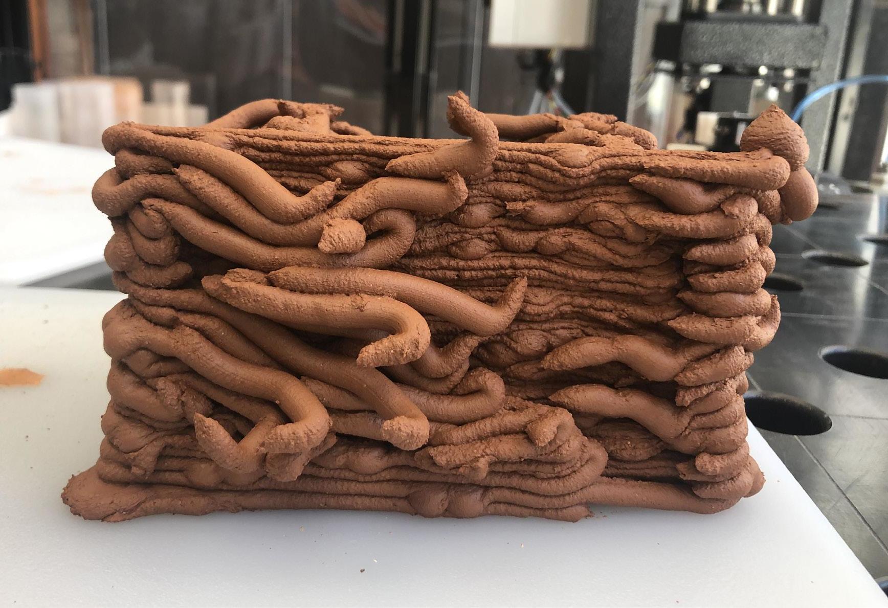
(1)-(2)Test 5, (3)-(4)Test 6 Image Source: Shubbaam (2)
(4)
BRICK TEST PRINTING
The layer heights is one of the important parameters in printing.
If the layer height is too high, the successive layers do not get a base support of the layer beneath as the clay layer settles down after printing. This causes irregularities in the print. Even if the brick gets printed, the clay layers that are not stacked and settled eventually crack after drying.
If the layer height is too low the nozzle drags the clay of the subsequent layers causing deformities. It also creates blobs of extra clay on the surface which distort the brick face. The blob of clay may also be a result of some extra points overlapping in the script which can be changed manually in rhino and grasshopper. (Refer Image 3 and 4).
For printing the final bricks we used 5mm layer height.
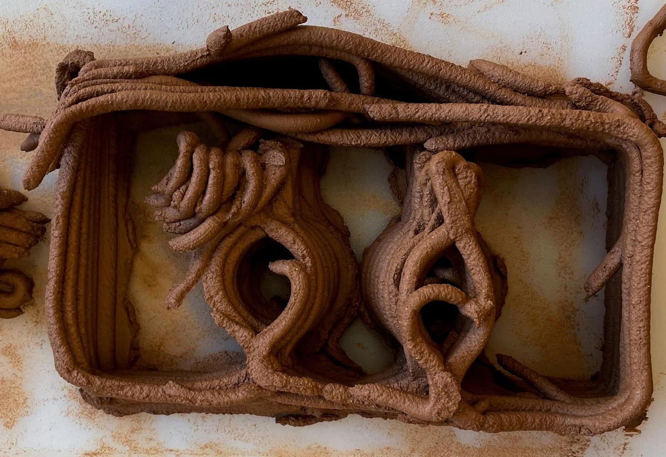
(1) Small size module brick test Image Source: Xiong
BRICK TEST PRINTING
We used manual control mode for printing the bricks. If the stop button was not pushed on time, the clay would overfloe and may cause. It was important to keep an eye on the print so that we could turn of the clay supply as soon as brick is printed to prevent excess clay damaging the brick.
In the first version script, we did not separate the convex surface from the concave surface.The junction between them would appear very crowded and unsightly. So we modified the script a bit by leaving a 5mm gap between the concave and convex surfaces. This prevented the overlap and the extra clay deposit at the junction.

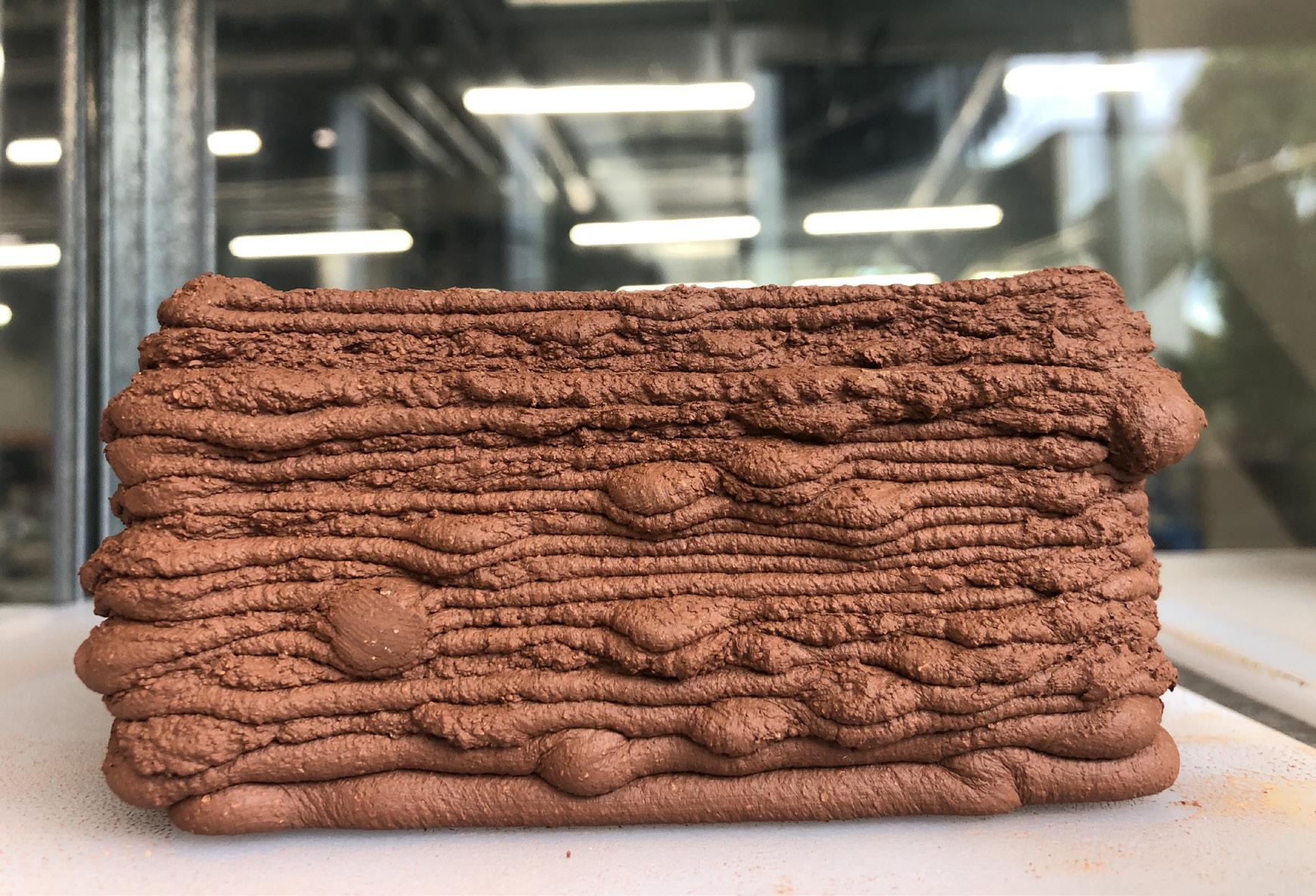
(1) Bigger size module brick test Image Source: Xiong
BRICK TEST PRINTING
We also realized that the brick was too small and the curved surfaces were too narrow to accommodate light fitting inside. So we increased the size of bricks and openings.
Following the changes and printing the bricks we observed that the width of each brick was too large, which led to the collapse of curved surfaces. In the subsequent design, we reduced the width of each brick so that the curved surfaces could support themselves.

(4)
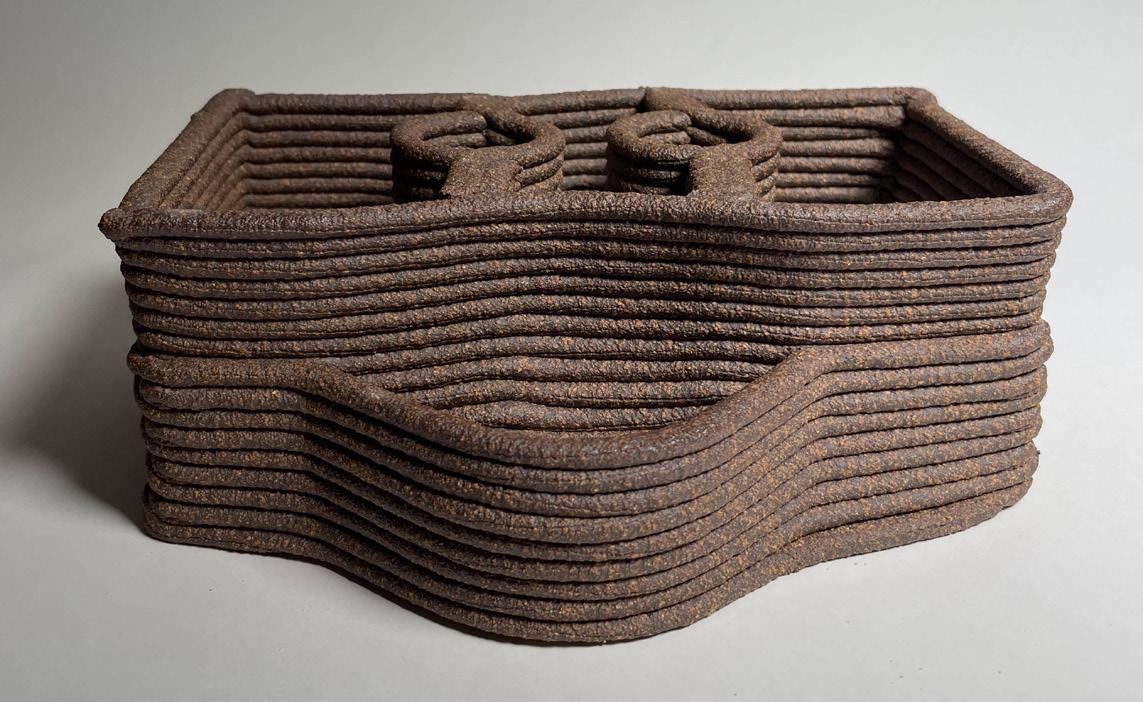
(5)
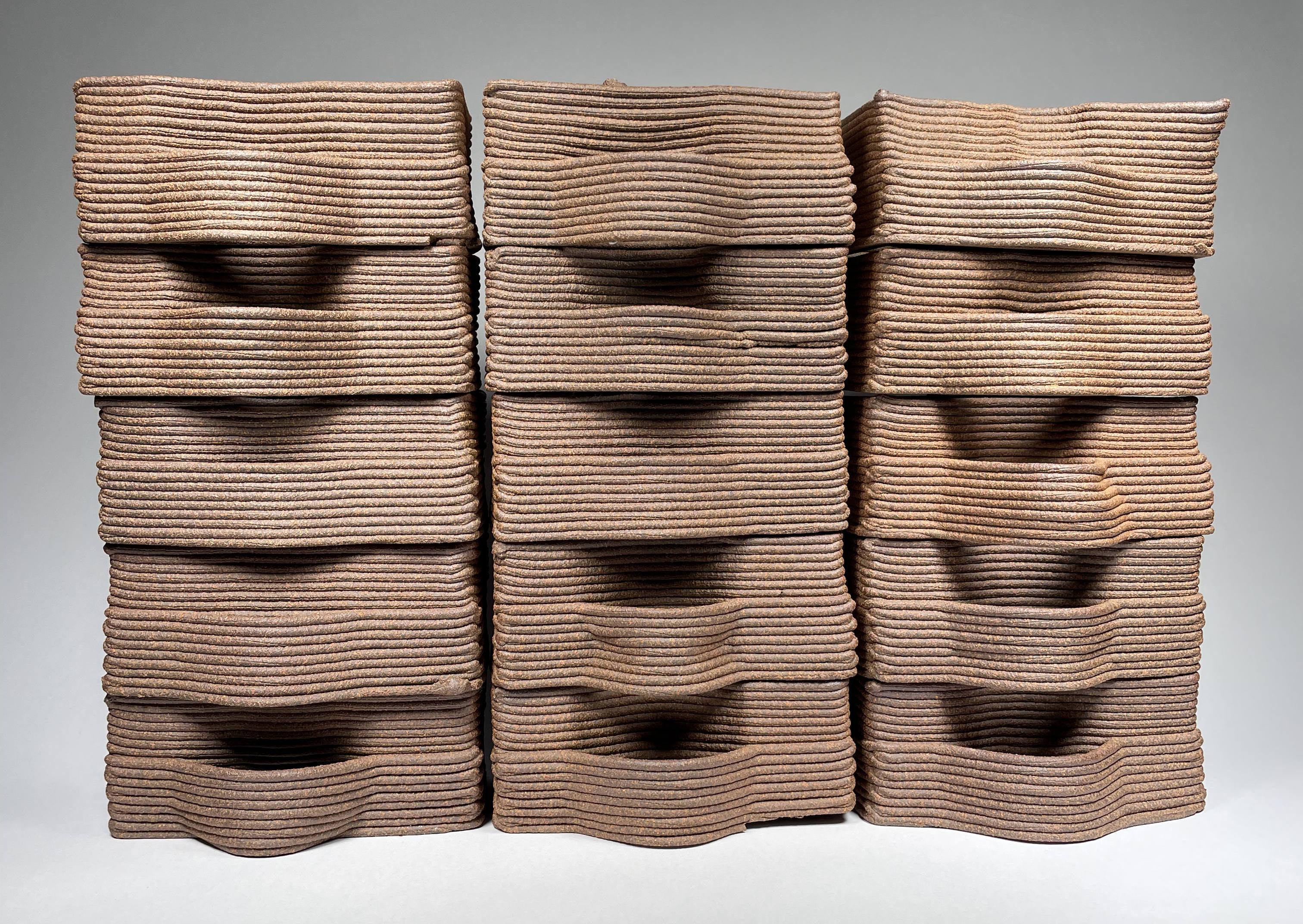
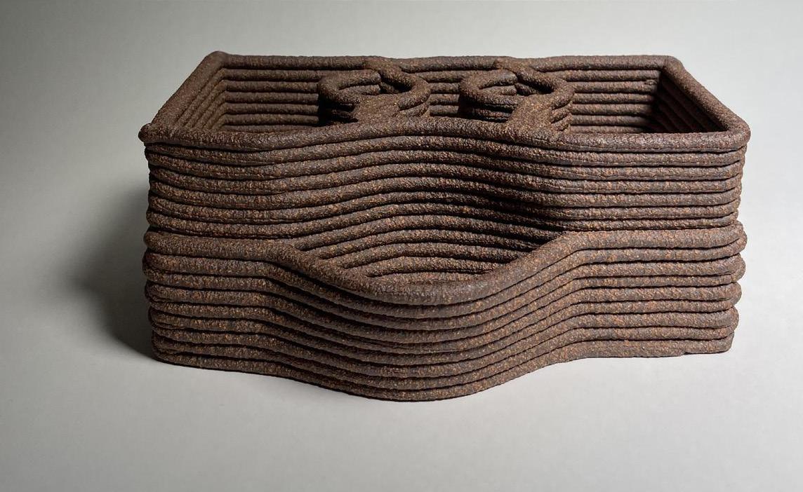
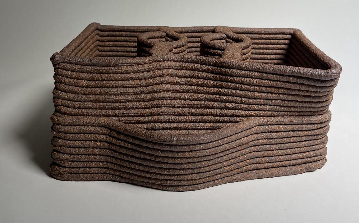
Some of the final printed bricks Image Source: Xiong (6)
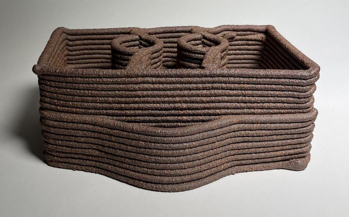
(7) (8)
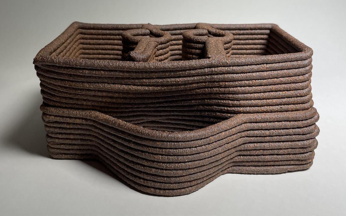

(9)

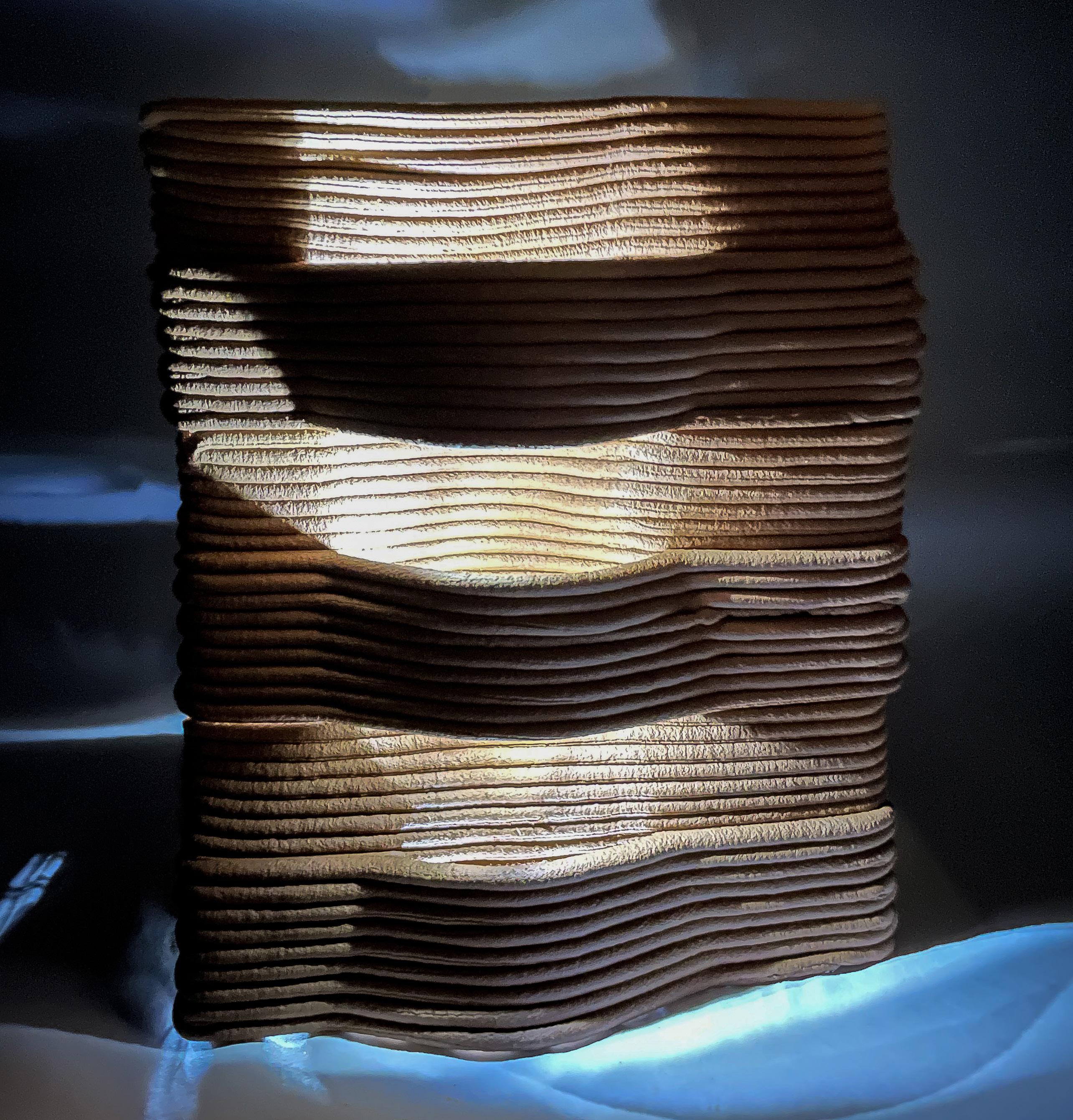
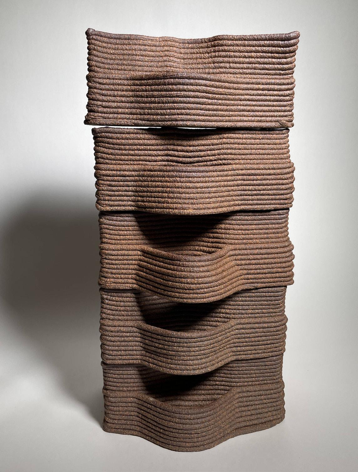
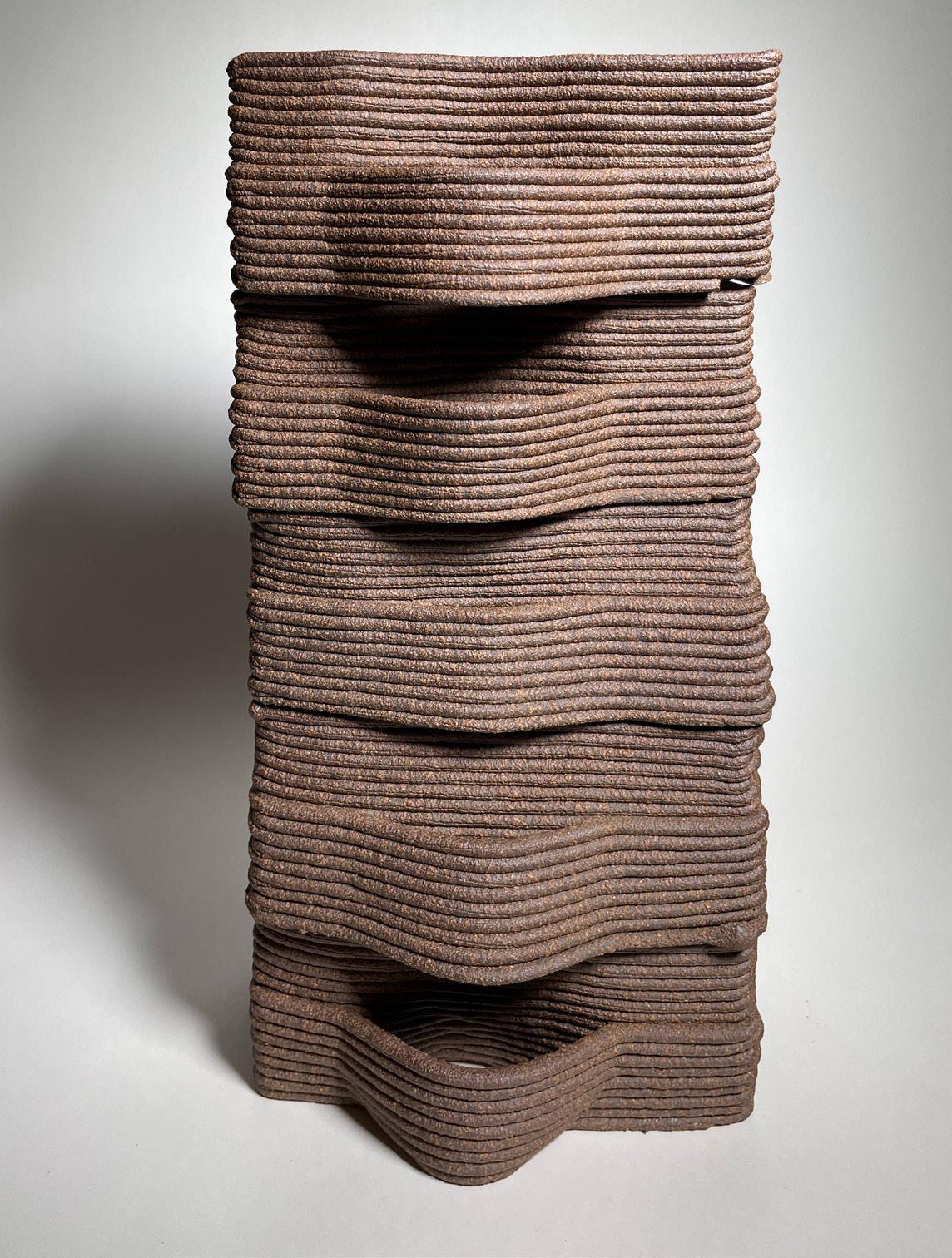
(1) Stacked bricks with LED lights creating a play of light and shadows Image Source: Xiong (2) Light emitting out from the weaved pattern at the back of the brick Image Source: Xiong


(1)Brick wall Image Source : Xiong