1. 2. 3. 4. 5. + 6. 7. IN GNDOUT 8. 9. 10. 11. PICO RASPBERRY PI hsmag.cc Issue #40 March 2021 Is this your next soldering iron? Pinecil PROJECTS Things to make with your $4 microcontroller Mar. 2021 Issue #40 £6 Add encryption to MQTT IOT Security How citizen scientists are looking after these lovely little honey-makers BEES BEES Screen printing in the digital age Laser cut printing ALUMINIUM FOIL CNC CROCHET LEDS

EDITORIAL
Editor
Ben Everard ben.everard@raspberrypi.com

to
HackSpace magazine
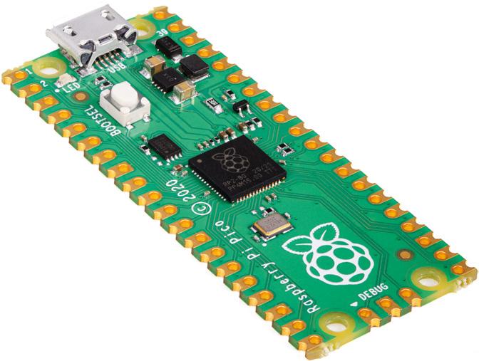
got a new tool in our maker’s toolbox that’s great for connecting things together With the launch of Raspberry Pi Pico, we’ve
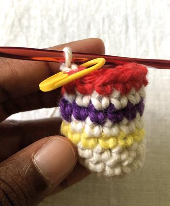
Last month was the most in-demand issue of HackSpace ever. With the launch of Raspberry Pi Pico, we’ve got a new tool in our maker’s toolbox that’s great for connecting things together. This issue, we’re going to keep looking at Pico – after all, a lot of readers will have gotten one free last issue – with some projects. Whether you like beeps and boops, or sparkly lights, we’ve got something for you. If you didn’t get the last issue, but want to join in the fun, don’t forget that you can get a free Pico when you subscribe to HackSpace magazine (from just £5 if you’re in the UK). For details, head to hsmag.cc/subscribe It’s not just Pico, of course. I really love it when our contributors bring together areas of making that don’t always seem that close to each other. This month, we’ll show you how to crochet your own resistor holder! Take a look at page 94 if you think your workbench needs more soft toys.
BEN EVERARD Editor ben.everard@raspberrypi.com
Got a comment, question, or thought about HackSpace magazine?
get in touch at hsmag.cc/hello
Features Editor
Andrew Gregory andrew.gregory@raspberrypi.com
Sub-Editors
David Higgs, Nicola King
DESIGN
Critical Media criticalmedia.co.uk
Head of Design
Lee Allen
Designers
Sam Ribbits, James Legg, Ty Logan
Photography
Brian O’Halloran
CONTRIBUTORS
Lucy Rogers, Drew Fustini, Jo Hinchliffe, Mayank Sharma, Marc de Vinck, Anuradha Reddy, Rob Miles, Andrew Lewis, Daniel Hollands, K.G. Orphanides, Stratos Botsaris
PUBLISHING
Publishing Director
Russell Barnes russell@raspberrypi.com
Advertising
Charlie Milligan charlotte.milligan@raspberrypi.com
DISTRIBUTION
Seymour Distribution Ltd 2 East Poultry Ave, London EC1A 9PT +44 (0)207 429 4000
SUBSCRIPTIONS
Unit 6, The Enterprise Centre, Kelvin Lane, Manor Royal, Crawley, West Sussex, RH10 9PE
To subscribe 01293 312189 hsmag.cc/subscribe
Subscription queries hackspace@subscriptionhelpline.co.uk
This magazine is printed on paper sourced from sustainable forests. The printer operates an environmental management system which has been assessed as conforming to ISO 14001.
HackSpace magazine is published by Raspberry Pi (Trading) Ltd., Maurice Wilkes Building, St. John’s Innovation Park, Cowley Road, Cambridge, CB4 0DS The publisher, editor, and contributors accept no responsibility in respect of any omissions or errors relating to goods, products or services referred to or advertised. Except where otherwise noted, content in this magazine is licensed under a Creative Commons Attribution-NonCommercialShareAlike 3.0 Unported (CC BY-NCSA 3.0). ISSN: 2515-5148.
WELCOME FREE PICO WHEN YOU PAGE 50
3 Welcome
GET IN TOUCH hackspace@ raspberrypi.com hackspacemag hackspacemag ONLINE hsmag.cc


4 Contents 06 Top Projects Exceptional artefacts made by everyday humans 20 Objet 3d’art Version two of a quite brilliant seven-segment display 22 Meet the Maker: Thea Flowers Modular synth sounds of the open-source variety 30 Columns Wood-turning as productive procrastination 32 Letters The public want more Pico stuff. Excellent! 34 Kickstarting Boost the brains of your Raspberry Pi 38 Pico projects More things to make and do with your $4 microcontroller 52 How I Made: CNC plotter Rescue broken hardware and turn it into an art vector 58 Interview: My Bees How one project is monitoring urban ecology 68 Improviser’s Toolbox Aluminium foil Make things with thin sheets of metal 37 06 SPARK LENS Cover Feature 38 94 Admit it: you’ve always wanted your own cuddly resistor Tutorial Crochet PICO RASPBERRY PI PROJECTS Do more with the $4 microcontroller 80


CONTENTS 5 Some of the tools and techniques shown in HackSpace Magazine are dangerous unless used with skill, experience and appropriate personal protection equipment. While we attempt to guide the reader, ultimately you are responsible for your own safety and understanding the limits of yourself and your equipment. HackSpace Magazine is intended for an adult audience and some projects may be dangerous for children. Raspberry Pi (Trading) Ltd does not accept responsibility for any injuries, damage to equipment, or costs incurred from projects, tutorials or suggestions in HackSpace Magazine. Laws and regulations covering many of the topics in HackSpace Magazine are different between countries, and are always subject to change. You are responsible for understanding the requirements in your jurisdiction and ensuring that you comply with them. Some manufacturers place limits on the use of their hardware which some projects or suggestions in HackSpace Magazine may go beyond. It is your responsibility to understand the manufacturer’s limits. 74 SoM PIO in MicroPython Get masses of data in and out of your Pico 78 SoM MQTT security Keep your IoT devices safe from prying eyes 80 SoM Laser cutter screen printing A modern twist on applying ink to surfaces 84 Tutorial Retro gaming Use a retro DB9 joystick with Raspberry Pi 400 88 Tutorial FreeCAD Curves: because bendy is trendy 94 Tutorial Crochet Make a woolly resistor 73 FORGE 102 Best of Breed Solar power units Harvest the sun’s rays – they’re free energy! 108 Review Pimoroni Pico Explorer Loads of add-ons for your Pico, all in one board 110 Review Pinecil smart soldering iron This handheld tool gets things hot. Smartly! 112 Review Ooznest WorkBee Carve wood with computer-controlled precision 101 FIELD TEST Meet the Maker Thea Flowers 22 Who else loved the soundtrack to Sonic the Hedgehog 2? 102 Add-ons to capture solar radiation as energy 20 58 06
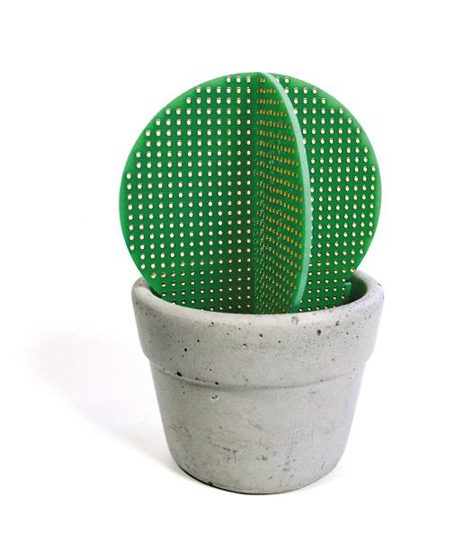
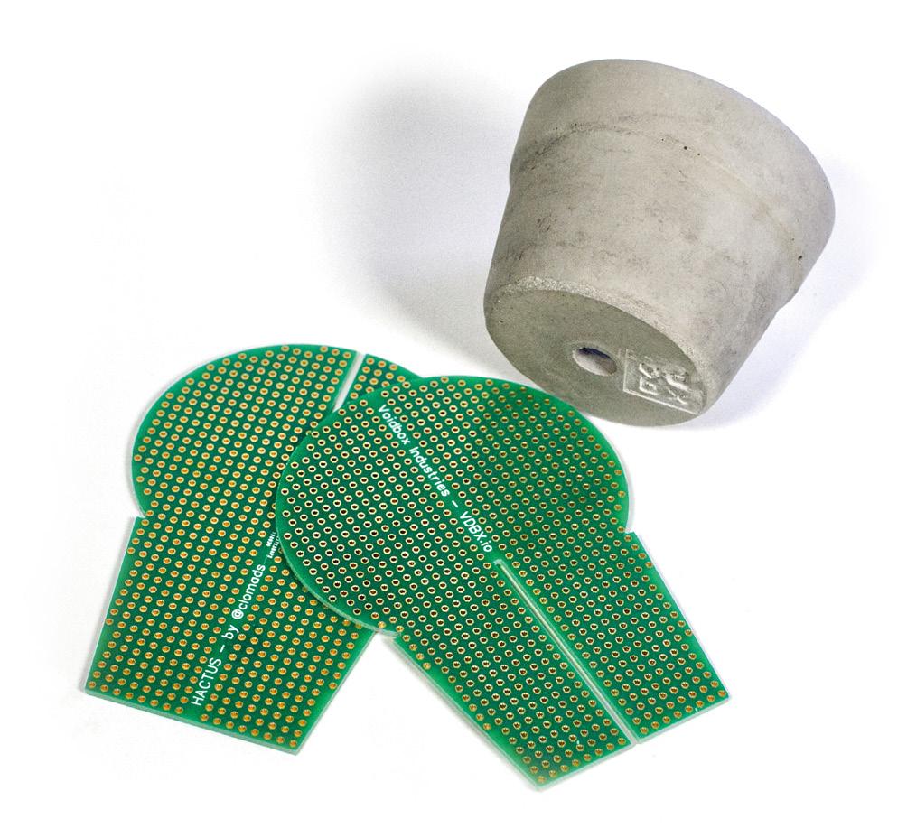
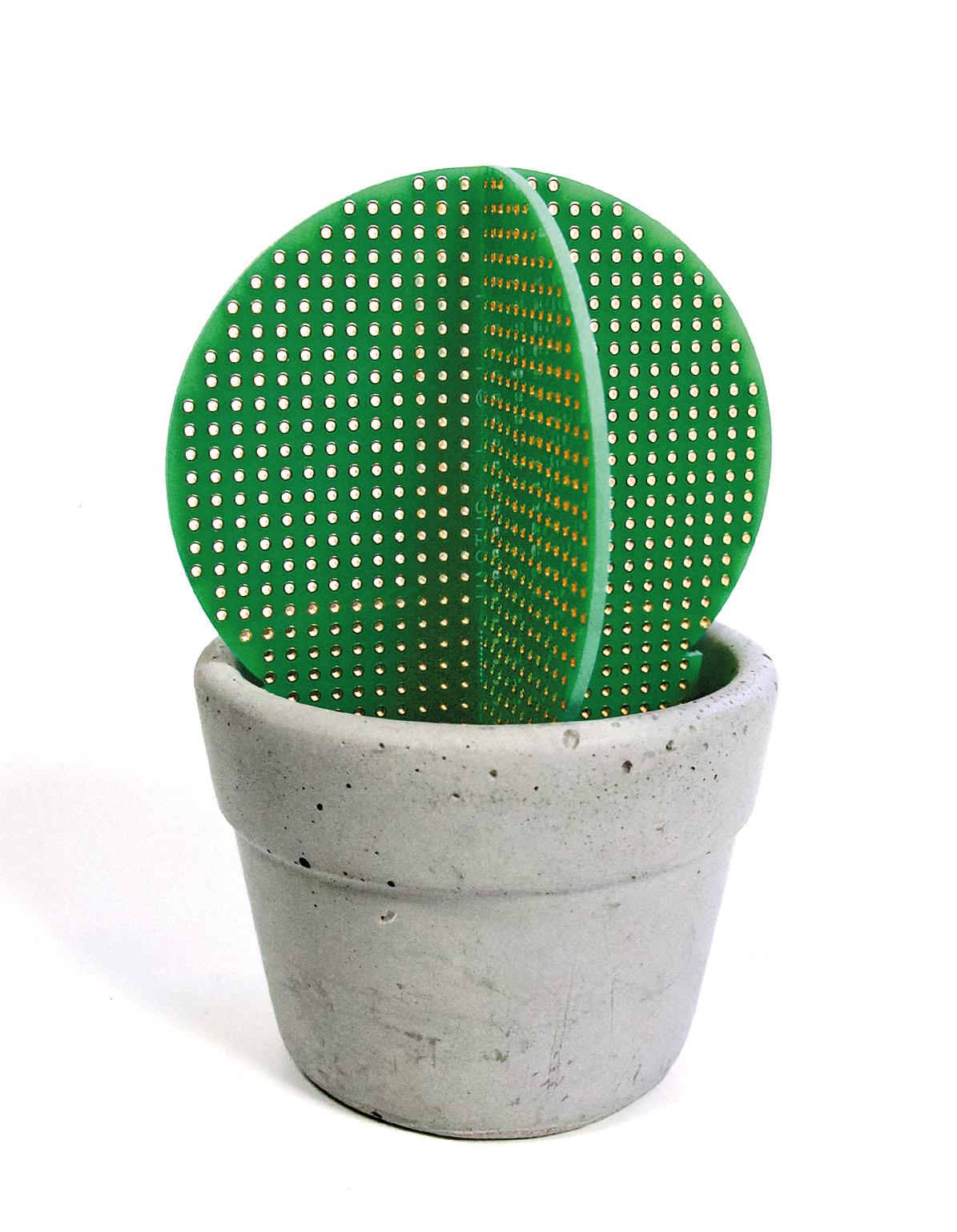
Hactus
By Chloe Madison hsmag.cc/Hactus
Do you ever wish you had green fingers, but find that anything you plant just withers and dies? Well, Hactus might be the perfect houseplant for you! The cunning play on concrete and perfboard, by the artist Chloe Madison, will never need watering, and an online, plant-based cactus makes an ideal base for electric tinkering.
Top Projects REGULAR 6
Right What
is art? I don’t know, but I like it
7 SPARK
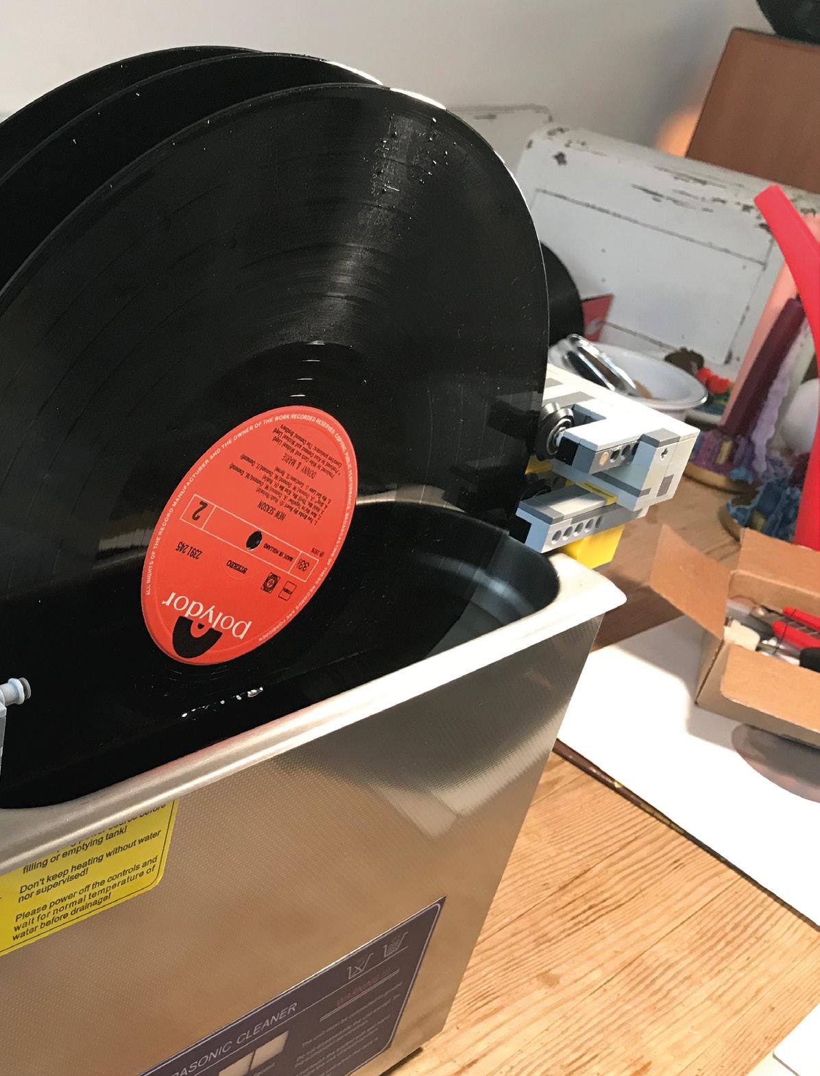
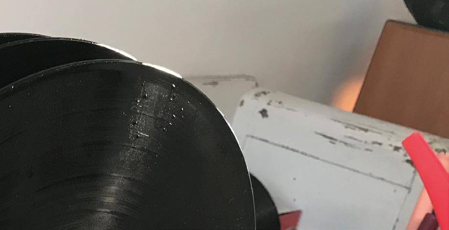
Lego + ultrasound vinyl cleaner
By Bas van Lieshout hsmag.cc/LegoSpin
Things you don’t know about if you only listen to vinyl from charity shops: the best way to keep your priceless records in audiophile condition is to rotate them through a solution, while ultrasonic vibration generates bubbles to gently dislodge the dirt and dust that accumulates in the grooves. You can buy machines that turn the vinyl in the solution, but as the owner of plenty of Technic Lego and a 9 V motor, Bas thought he’d have a go at his own implementation. This device rotates the record within the solution a set number of times and, rather than spin via the axle at the centre of the disc, it turns the edge of the disc instead (crucially, that’s the bit where no audio information is stored).

Top Projects REGULAR 8
Right Bas doesn’t believe in genres; there’s only good music
9
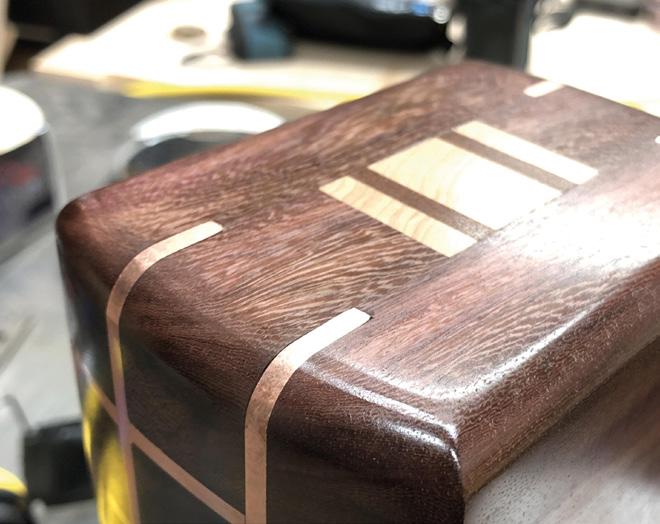
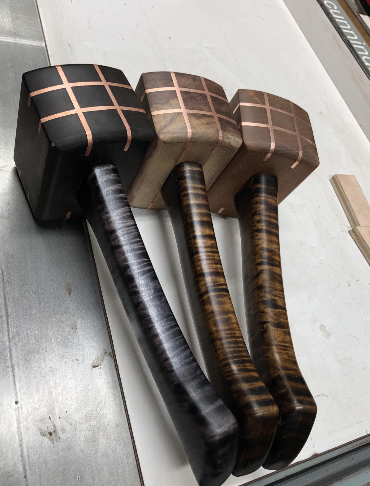
Copper-inlay mallet
By Cunningham Woodwork cunninghamwoodwork.com
These mallets, by Cunningham Woodwork, are a great example of a concept that we’ve touched on before: if you’re using a tool every day for your work, you want it to be the best tool that you can possibly make/afford. These are made with a traditional joint of a wedged mortise and tenon, with the handle going through the head of the mallet, and wedged in place with two different pieces of wood to keep a tight fit. What really sets these mallets apart is the decorative copper inlays on the faces of the mallet. You might imagine that the combination of hard metal and soft wood would make this hard to get right, but if you go slowly, the copper is just about soft enough to work with on carbide-tipped tools, such as a router and band-saw.

Top Projects REGULAR 10
Right
By Odin, whoever wields this is sure to have some fun
11 SPARK

12 Top Projects REGULAR

Gigaduino
By Zach Hipps of byte sized engineering youtube.com/bytesized
This is no ordinary Arduino…this is a 12× scale model of an Arduino, CNCed out of wood, with a mix of wooden and 3D-printed components and connectors. And while it’s maybe a little bit impractical for embedded work, its creator, Zach Hipps, has embedded an Arduino inside it, making it an embedded, embedded device.

13 SPARK
Left The Gigaduino makes your code twelve times bigger and better
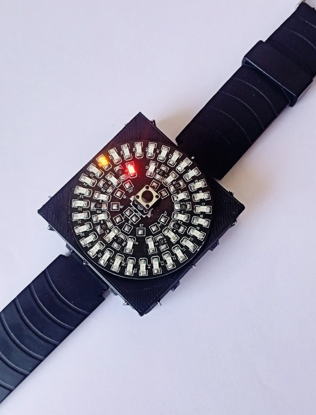
Analogue + digital watch
By maker_ATOM hsmag.cc/AtomWatch
This brilliantly bonkers design uses an Arduino Pro Mini, a DS1302 RTC module, LiPo battery, and TP4056 charging module, which protects the battery from overcharging. The components are stacked in layers, giving the watch a chunky feel on the wrist, like a Rolex or a TAG Heuer. To cut down on size, the watch face has only 30 LEDs to represent 60 minutes. Despite this, the wearer can still perceive time passing. If you don’t have a second hand/display, a digital watch is only accurate to within plus or minus one minute anyway, so it’s not as if accuracy was ever going to be a paramount consideration.
Below The 42 LEDs are connected using a technique called Charlieplexing


Top Projects REGULAR 14

15
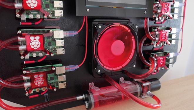
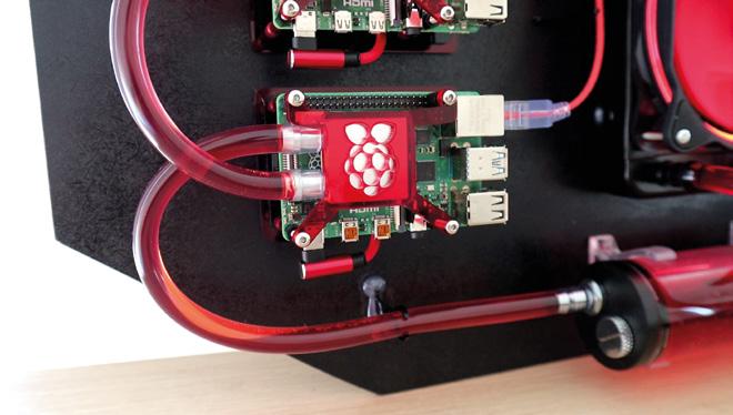
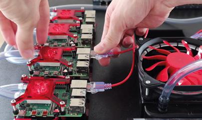
Water-cooled Pi Cluster
By Michael Klements hsmag.cc/PiCooler
Michael Klements has already been playing with cooling solutions for the Raspberry Pi –earlier this year he built a water cooling rig for a single Raspberry Pi, a project that he admits was “crazy overkill”. This cluster, on the other hand, makes a bit more sense. He’s used a 120 mm fan, an off-the-shelf water cooling kit, laser-cut acrylic to hold the cooling pads onto the Raspberry Pis, and eight Raspberry Pi 4s mounted onto 3 mm MDF, with aluminium standoffs to keep some air circulating.
The build write-up he’s put together is a thing of beauty – apart from the super-computer he’s built, we’re also impressed by the clean Dremel work.

Top Projects REGULAR 16
but
Right
When it launched, the Raspberry Pi 4 had a reputation for getting a bit warm under heavy load…
this is just silly. And magnificent!

17 SPARK
Suzuki Hayabusa
By Samy hsmag.cc/CardBike
Because of the nature of HackSpace magazine and the people who read it, we’re used to seeing designs put together in some sort of software package first. Whether it’s Inkscape, for laser-cut models, or something more advanced, like FreeCAD or KiCad, the precision you get from designing on the computer, then fabricating from those plans, gives a satisfying sense of predictability.
That’s why we love Samy’s work here. This cardboard Suzuki motorbike was modelled entirely by hand using… a picture of the bike taken from a Google image search. That’s it – but it was enough to make this incredible finished artwork.

Top Projects REGULAR 18
Right Even the detailing on the engine is spot-on

19 SPARK
Objet 3d’art
3D-printed artwork to bring more beauty into your life
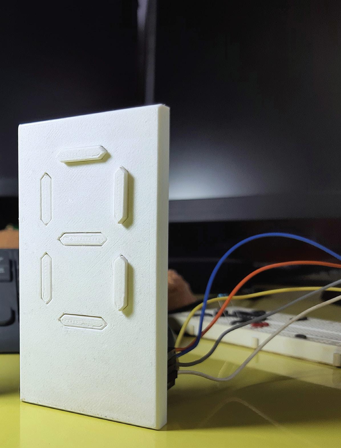
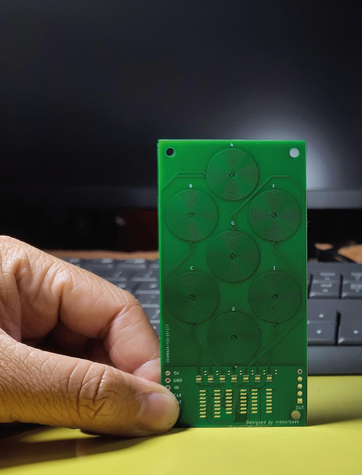
We featured an earlier iteration of this sevensegment display in the middle of 2020, and it was pretty clear then that, even at an early stage, it was a brilliant idea. Its creator, Neeraj Rane, said at the time that he wanted to minimise the size of the electromagnetic actuators that move the seven segments in and out, and he’s done that by ditching discrete components, and instead printing the coils of the magnets onto the PCB. This method, inspired by Carl Bugeja, has resulted in a slimmer, more useful creation, in a 3D-printed body.
youtube.com/IndoorGeek
Meet The Maker: Thea Flowers
Making music one bit at a time
Modular synths are an endlessly fascinating wormhole of weird sound. Devotees will obsess over what, to our barbarian ears, are just endless versions of the same thing, in a way that’s completely cool and endearing. It’s a world of enthusiasts making things they love – one of whom is Thea Flowers. Thea’s been making modular synths under the Winterbloom banner for three years now, and anyone with any musical taste will instantly recognise the classic sounds that her stuff makes. What’s more, everything she does is open-source.
“I got into modular synths because of electronics. I’ve been playing music most of my life now, and I’ve always liked synthesisers and the idea of them, but I’ve never really got into modular synthesisers. I heard about modular synths a few years ago, and my immediate reaction was ‘that’s not something that I want to do’. However, when I started getting into electronics, I was building custom keyboards, mechanical keyboards, and stuff like that. I did music and I wanted to explore standalone synthesizers.
“The idea of building a standalone synthesiser by yourself is daunting; you have to do so much. So I started looking for a way to build synthesisers without having to know everything out of the gate, to build a full synthesiser entirely by myself. I started to look back into the modular stuff and saw like, this is actually really awesome. There’s so much neat stuff going on, so many unique little modules – this is perfect! I can experiment, I can play around with stuff, I can make tiny single-purpose things that

don’t require me to have a PhD before I even start creating things.
“It was more about the desire to create something physical than the desire to create music. It’s the tinkering aspect – I like the idea of small singlepurpose machines that work together.
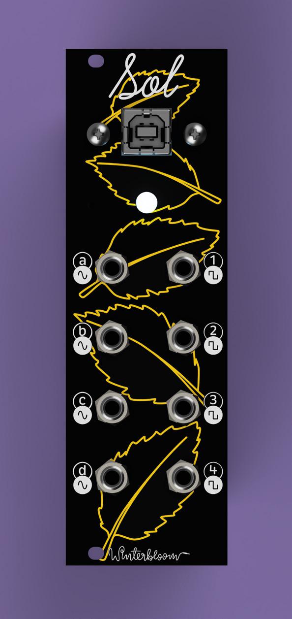
“My first module is called Sol, and it’s a MIDI-tocontrol voltage (CV) model. In the world of modular synthesisers, everything talks to each other using CV; in the world of computers, everything talks to each other using MIDI. Sol is the bridge between the two. You can hook it up to your computer and send it MIDI notes – Sol will convert that to CV.
“What’s cool about Sol is that it’s running CircuitPython. You can change how it translates MIDI information to CV. You can make it do all kinds of neat stuff. Instead of outputting a note, you can make it output a note plus some vibrato; you can make it change the scale of the note. You can also make it play the role of smoother modules that you may not have if you’re just starting out. It can be an envelope generator, it can be a little frequency oscillator if you want it to do that. Sol is really customisable and it’s a little reprogrammable brain that can process MIDI and spit out CV.
“Big Honking Button is technically a sampler with a button on it, and when you press the button, it honks. It also runs CircuitPython, and it’s customisable, so you can make it do all kinds of cool stuff. For example, there are samples on there for doing percussion. One of my favourites that I wrote is a cycle program, so you tell it a list of samples, and every time you press the button, it will cycle through them. You can have a drum sound and
22 Meet The Maker REGULAR
 Right
The Big Honking Button: a reprogrammable, open sampler, running CircuitPython
Right
The Big Honking Button: a reprogrammable, open sampler, running CircuitPython
 Right
Thea was inspired to create a synthesizer by her lifelong love of the music on Sega Genesis [aka Megadrive] games
Right
Thea was inspired to create a synthesizer by her lifelong love of the music on Sega Genesis [aka Megadrive] games
a snare sound, and alternate between them every time you hit the button.
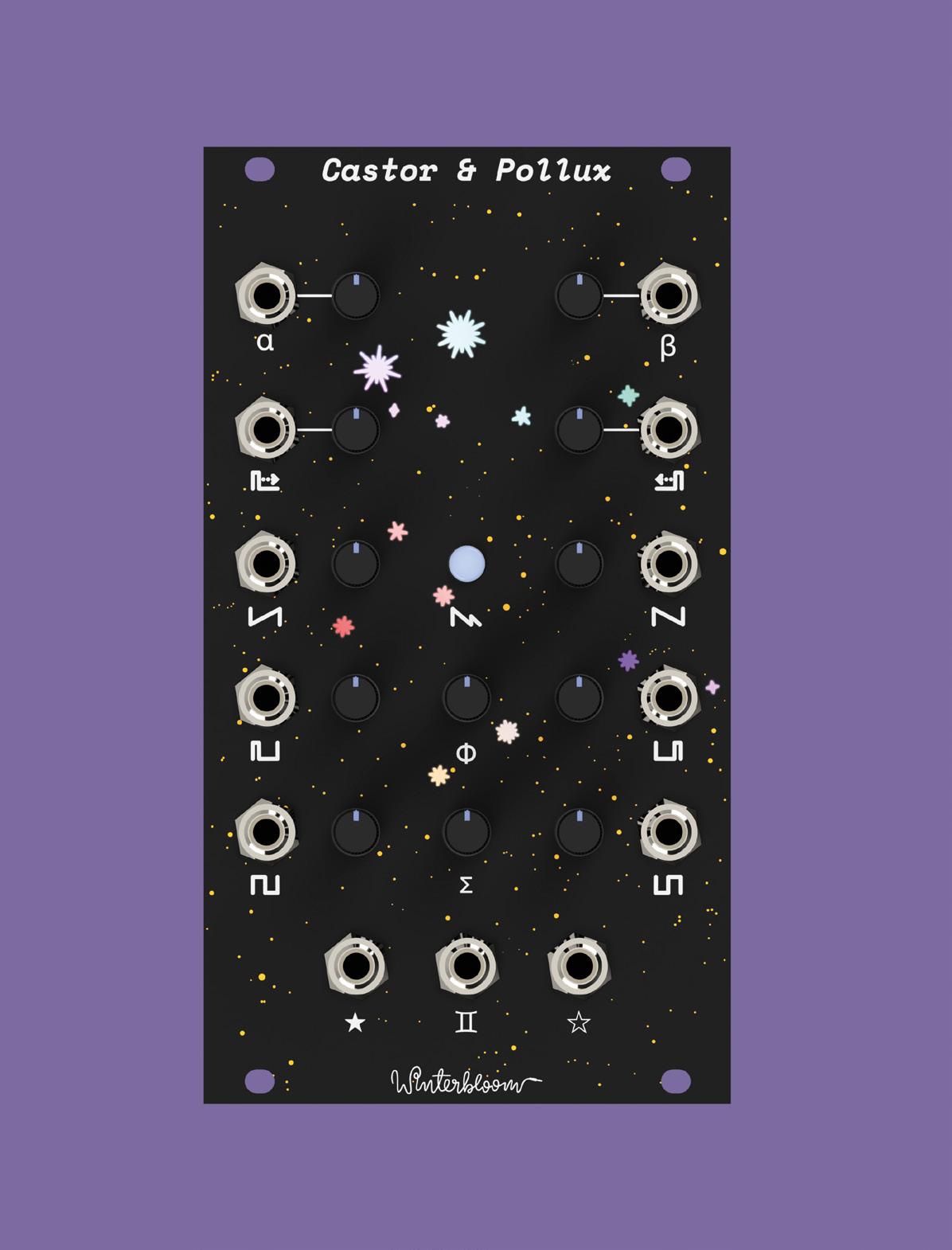
“The thing I’m working on at the moment is called Castor & Pollux – it’s my favourite module that I’ve designed so far. It’s beautiful. It’s the module that I’ve wanted to make since I started making modules. It’s a Roland JUNO-inspired oscillator. It basically brings the voice that the Roland JUNO had into the Eurorack form. That voice is legendary; it’s built into everything. You could throw a rock at the 1980s and hit 17 songs that had the JUNO on them.
“It was the first polysynth that could stay in tune. Every other synth at the time used a lot of analogue circuitry that was all temperature-dependent. It would be out of tune when you got on stage, and by the time you’d fixed the tuning and started playing, 15 minutes later it would be out of tune again because it had warmed up a bit.
STAY TUNED!
“The Roland JUNO took a different approach, and because of that, it stayed in tune. You could plug it in and it would be good to go. It got a lot of popularity because of that, and also because of the way that it sounds. It’s in so many songs; Cyndi Lauper’s breakout album, Time After Time, that’s all the JUNO; a-ha’s Take On Me, that’s the JUNO; Sweet Dreams by the Eurythmics, that really awesome intro, that’s the JUNO. It’s so perfect. I wanted to bring that voice to Eurorack.
“This has actually been done before – someone straight up took the oscillator design and put it into Eurorack, and that’s awesome. I wanted to do something a little bit weird, though. I decided to take two of them. This is actually two oscillators that are based on the JUNO oscillator, so it can overcook some of the limitations that were in the original JUNO design. Because the JUNO only has one oscillator per voice, it sounds a little thin sometimes. The way that Roland got around this was by adding chorus to the end of it to make it a little bit thicker.
“But Castor & Pollux actually has two complete oscillators that are independent and can be configured to follow each other. That gives you the ability to stack detuned oscillators together to create these massive-sounding voices that just weren’t possible on the JUNO. It’s inspired by the JUNO, it sounds a lot like the JUNO, but it also has its own unique voice that just wasn’t possible on the JUNO, and I really love that.
“Big Honking Button got way more popular than I ever expected. I expected that people would get it and they’d immediately change the sample that’s on
it. It’s designed to do that. It’s supposed to be silly to draw you in, but then you realise that you can get it to play any sample you want just by hooking up a USB cable and swapping out the sample. You can also change the code on it because it’s CircuitPython.
“However, there are a lot of people who bought two of them and left one of them as the honk – the default program, the link sound. People send me videos of themselves all the time using this honk in otherwise straight-up awesome music. I never anticipated Big Honking Button to be what it is. It’s
That voice is legendary; it’s built into everything. You could throw a rock at the 1980s and hit 17 songs that had the JUNO on them
silly; I love it. At least from a creative perspective, Castor & Pollux is the module I had in my brain when I started doing this. To see it become a thing, and the reception that it’s had so far, is incredible. It’s become a lot bigger than I’ve anticipated, and a lot bigger than anything else I’ve done.
“We’ve just sold out the pre-order for the first run. I’m working with our contract manufacturer to do a second run. That’s really exciting. I’ve never done

25 SPARK
” ”
Below
Just some of the sell-out first run of Castor and Pollux – it’s like the Roland Juno, but twice as good

anything where it sells out before I’ve even shipped the first one! I’m really happy about it. It’s less ‘coping’, and more ‘being really excited’ and trying to maintain the high level of quality that I have for everything. The first run was 150, and we’ve sold every single one of them.
“There’s a mix of people. There are certain demographics of people who are into Eurorack synthesizers, right? People who have disposable income and who are technically inclined. I’ll also say I’m really happy that some of my first supporters and biggest customers are friends of mine that are part of a transgender Discord.
product, and their support is so important to me. They’re repeat customers; they give me great feedback, and they really make feel like I’m part of a community versus making a product that some people are buying. It’s collaborative in a huge way to send over some sound samples and have them give me feedback so that I can iterate on that.
“There’s a lot of wealthy white dudes in Eurorack; there’s also a huge part of it that is people who aren’t necessarily rich with disposable income, and I’m glad that my customers come from a mix of both. It’s important to me that I make modules that are approachable and obtainable. If every module I made was $600 and I was only selling to ridiculously wealthy people, I would not be happy about that. It’s a mix of people – I’m happy about that.
“Because we don’t have distributors outside of the US now, it’s mostly US-focused, but we do get quite a lot of orders from the UK and Australia, which is really cool. I would love to be able to ship to them more cheaply. We are talking to two different distributors in the UK, and hopefully that’ll work out.
The point isn’t that I’m making synth modules. It’s that I’m making things that people use to learn ” ”
“These people have watched me take Castor & Pollux from a circuit on a breadboard to a finished

“Everything I do in terms of Winterbloom is open-source. From the hardware design to the bill of materials to the firmware, to the factory setup scripts that we have for each module, everything is open-source.
“Some people will copy the work, and I want them to. I want to see people do that. I’m happy when that happens. That’s part of the point. But from what I’ve noticed, people are willing to pay for you to create something for various reasons. It could be the convenience of having it built for them, or the assurance that someone who knows what they’re doing put it together, or it could just be that they want to support you and want to give you money so you’ll continue to do what you do.
“I put my stuff out there as open-source, and I’m not bothered if someone wants to go and take it and make it themselves.
“The point isn’t that I’m making synth modules. It’s that I’m making things that people use to learn. The education piece is the most important piece to me. I want my modules to be fun, but I also want my modules to be educational in some way. You can see that throughout everything I do. You can take Castor & Pollux as a user guide, and in many ways, it’s an introduction to what synthesis is.
Meet The Maker REGULAR 26
Above Sol, Thea’s first module, converts MIDI input into control voltage
Right Thea’s products all conform to the Eurorack form factor – the gold standard of modular synths
“I owe my entire career to open-source. I didn’t go to college, so in terms of learning how to program, and learning how to do all this stuff, it’s all because other people decided to make stuff open-source, so that I could learn from it. It feels like an obligation, but also I have a huge desire to give back.
COMMUNITY IS KEY
“You can’t develop a module in a vacuum, right. You can’t develop something that’s designed to work with other pieces of equipment if you have no idea what other people are going to use it for. A lot of the feedback I got from Castor & Pollux was around the controls on the front of it. I got really good feedback on tuning it; people were concerned about these little trimpots on here. Because it is a little hard to nail the exact setting on something that small. Based on that feedback, I made a little edit in software to make the tuning knobs non-linear so that the centre of the range is more spread out, so you have an easier time dialling in the note that you want. It’s little things like that, quality of life, that I get from the community.
“[Before getting into hardware] I had been a software engineer for over a decade. I mostly focused on the Python community, developer tooling, and APIs and stuff like that. I’m a Python Software Foundation fellow, so I’ve done a little bit in the Python community.
“I’m relatively new to the hardware world. I’ve been really happy with how, over the last three years or so, PCB prototypes, and, even small-scale contract manufacturing, have become so much more accessible to people. If it weren’t for contract manufacturers willing to do small runs of things, if it weren’t for PCB services like OSH Park and others, I couldn’t even do this. It would be impossible.
“People ask me all the time, ‘how do I get into doing hardware stuff?’ And the best answer I have is: find a community. Go and seek out people who are doing things that you want to do – surround yourself with those people. Having a community is the best way you’re going to learn, and the best way you’re going to be successful. You need people to interact and learn from and share with. That is the most important thing you can do. You can not learn any of this stuff in a vacuum.
“I could not have done this without the modular synth communities I’ve been a part of, and the Adafruit community. Scott Shawcroft, the CircuitPython project lead, once spent like four hours helping me debug the first board that I had designed. He didn’t have to do that, but he did. Community is essential.”
27 SPARK
Right The best way to learn a new thing is to find a community – luckily, Open Source Hardware people tend to be willing to share their knowledge
Beginner’s Guide Raspberry Pi

Inside:
• Learn how to set up your Raspberry Pi, install an operating system, and start using it
• Follow step-by-step guides to code your own animations and games, using both the Scratch 3 and Python languages
• Create amazing projects by connecting electronic components to Raspberry Pi’s GPIO pins


Plus
The only guide you need to get started with Raspberry Pi £10 with FREE worldwide delivery THE OFFICIAL
much, much more!
Buy online: magpi.cc/BGbook Now
includes Scratch 3 projects!


£10 ONLY MAGAZINE FROM THE MAKERS OF THE BEST PROJECTS FROM HACKSPACE MAGAZINE THE ULTIMATE SKILLS, TRICKS, AND MAKES AVAILABLE NOW
Procrastination
Restarting an old hobby
 Lucy Rogers
@DrLucyRogers
Lucy is a maker, an engineer, and a problem-solver. She is adept at bringing ideas to life and is one of the cheerleaders for the maker industry.
My wood-turning lathe has been gathering dust for too many years. It is one of those things that I am completely present in – for it’s not wise to daydream with sharp tools and a lump of wood spinning fast next to you.
However, I haven’t used it in a long time. It hadn’t even been set up properly from my last move – nearly three years ago. And it was hardly used in the workshop it was in before that.
So I decided this year it was either use it – or sell it on. The lathe is large. I had great plans to make candlestick holders, about 1 m tall and 0.15 m in diameter. So, 15 years ago, I bought a lathe that would be able to cope with long and chunky lumps of wood. It also has lots of paraphernalia – from chisels to finishes, sandpaper of many grits, to a buffing mop. Plus, the numerous blanks and bits of tree that I’ve accumulated over time.
Pause while awaiting delivery of switch for grinder.
Day five: Fix the grinder.
Day six: Set up the grinder/sharpening system jig and baseplate. Need to raise the grinder 35 mm. I have 40 mm wood …
Day seven: Cut wood for packing and for securing onto the stand. Need to remove the bracket on the grinder. Tools elsewhere.
Day eight: Progress being made on the grinder jig. Took ages to rummage through the random bolt box to find ones that would work.
Day nine: Grinding jig complete – plus new guards fitted.
Even if I do end up burning the first seven, it still means I have practised my skills
To keep myself on track, and for a bit of accountability, I decided to tweet my daily progress:
Day one: Find the actual lathe – buried under garden furniture, boxes, and random pieces of wood.
Day two: Remove surface rust and mould from tools and lathe.
Day three: Discover broken plug and replace.
Day four: Find and attach to faceplate a wood blank. Sharpen tools – grinder dead. Whetstone and diamond files tried. More practice required.
Day ten: Chisels now shorter, and sharper – and some are slightly blue on the corners.
Day eleven: After ten days of faff (spread over about 2.5 weeks), which is approximately ten hours in the workshop, I finally made wood shavings!
No wonder I’d been putting it off. But now it’s all ready, and I am taking Andy Coates’s advice (@AndyWoodturner): “Take ten identical bowl blanks. Turn the same bowl ten times. The last three will be almost identical – and right. The others you can burn – you’ll want to. Do 20? Even better, 30? Now you’re talking.”
I’m starting with the bowl blanks I already have. The wood is a sunk cost – I didn’t need to justify it with a final product, which gives me the freedom to play and try things. Even if I do end up burning the first seven, it still means I have practised my skills. And that stack of wood is no longer burning into my consciousness and taking up mental and physical space.
Rogers COLUMN SPARK
Lucy
30

Letters
If you have something you’d like to get off your chest (or even throw a word of praise in our direction) let us know at hsmag.cc/hello
MORE PICO PLEASE
Right, I’ve got my Pico, got MicroPython installed, built the traffic lights, attached a buzzer, and I’ve got a shopping list of add-ons ready for when payday comes. What now?
Rachel Colchester
Ben says: What now? Why, turn to page 38 of course –we’ve been absolutely hammering our Pico, especially with the PIO features that make it so powerful.
YOU MADE A TIME MACHINE?
I really must take issue with your Letters page, issue 39. The letter in question mentions a DeLorean, while the image clearly shows the car from Ghostbusters. This is a fail. But on the other hand, it did lead me to stumble across a documentary on John DeLorean and his dodgy dealing on the BBC the other week. So a fail, but a productive fail.
Worcester
Ben says: I literally have no idea how this happened, but I really don’t mind – Ghostbusters is the best film ever, after The Expendables 2, so we’ll take any excuse to talk about it.

Letters REGULAR
ATTENTION ALL MAKERS!
32
Paul
CHEERS FOR THE PICO!
I wasn’t looking for a cheap, dual-core microcontroller, but now that I’ve got one I’m not giving it back! I’ve no idea how you are able to give away something so useful, so cheaply, but I’m not going to complain. Having to learn C was always a barrier to entry to learning Arduino, so I’m pleased that there’s now a cheap way to show my nieces how to make things flash and beep with Python instead.
Huw Jones Telford
Ben says: As I recall from business studies lessons, the cheaper things are, the more you have to sell to make the same amount of money. Based on the fact that I think the plan for the Pico is to sell scullions of them, which suits me: as you say, controlling hardware on Python is so, so much easier than doing it with C. Let a thousand embedded engineer flowers bloom!


HOT AIR
Last issue, you got hold of a hot air reflow station for melting solder paste. It looked a bit like a hair-dryer, but with a dial to control the temperature of the air. I’ve never used one of these things before – in fact, I’ve never used surface mounted components at all. Is there any chance of you publishing a guide to help me get started?
Suraj Chennai
Ben says: Sticking part x to part y is the easy part – we prefer to link a skill to a project, so we’ve got a few parts on order that’ll be used to demonstrate a few surface mount soldering techniques. So in short, yes, but we don’t know how long they’ll be stuck at customs.
SPARK 33
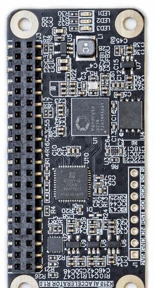
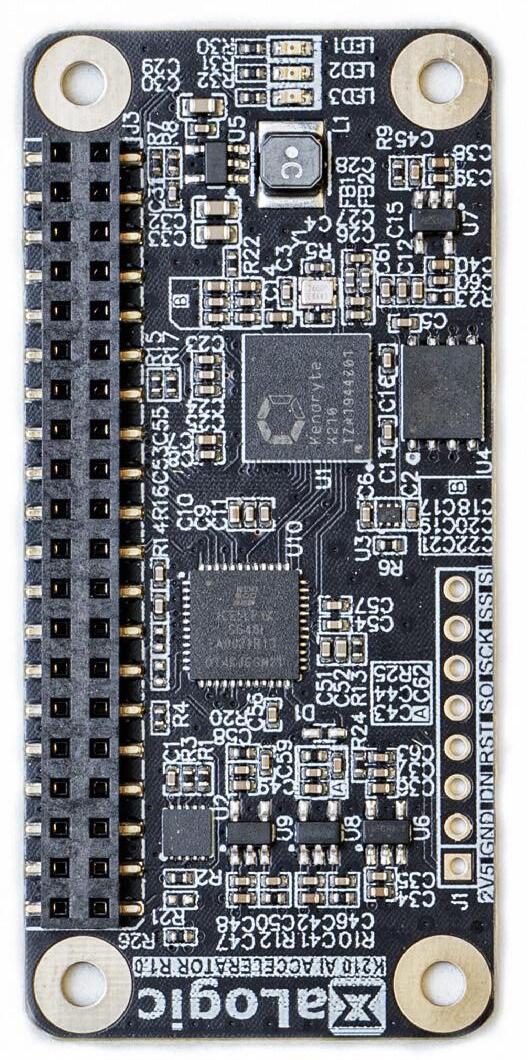
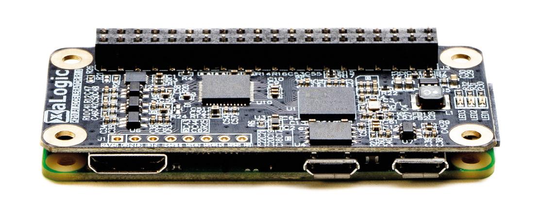
CROWDFUNDING NOW K210 AI Accelerator
Give your Raspberry Pi a performance boost for machine learning
$38 crowdsupply.com Delivery: May 2021
You can run neural networks on your Raspberry Pi, but they’re demanding and can suck up a lot of your processor time – especially if you’re using a Raspberry Pi Zero. This HAT lets you offload some of the processing of neural networks to an additional processor, the Kendryte K210. This isn’t as powerful as some of the other neural network accelerators – running at about 0.5 TOPS. But it doesn’t suck up too much electricity and is convenient to use.
Pre-trained models will be available for object detection and face detection, but if you want to dig into TensorFlow, you can create your own. While TensorFlow development is quite an involved affair, you can run existing models without too much difficulty from Python.
If you’ve already got a heavy workload on your Raspberry Pi, this is a great way to add a little extra compute power to enable AI.
34 Crowdfunding now REGULAR
BUYER BEWARE !
When backing a crowdfunding campaign, you are not purchasing a finished product, but supporting a project working on something new. There is a very real chance that the product will never ship and you’ll lose your money. It’s a great way to support projects you like and get some cheap hardware in the process, but if you use it purely as a chance to snag cheap stuff, you may find that you get burned.

35


LENS
HACK MAKE BUILD CREATE


the technology that’s powering the future It’s shiny, it’s malleable, and it’s conductive: the perfect material for playing with IMPROVISER’S TOOLBOX: ALUMINIUM FOIL Scavenged hardware from old printers finds a new, useful life controlled by a Raspberry Pi HOW I MADE A CNC PLOTTER 52 PG 68 PG What cheap, off-the-shelf hardware can teach us about the world of urban ecology INTERVIEW: INTERNET OF BEES 58 PG PG 38 PICO RASPBERRY PI PROJECTS Things to make and do with your $4 microcontroller
Uncover
PICO RASPBERRY PI
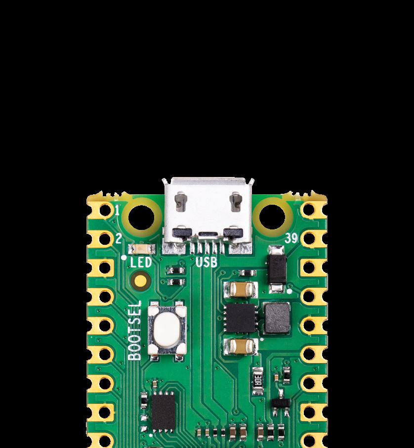
Raspberry Pi Pico Projects FEATURE 38
If you got your hands on HackSpace magazine issue 39, then you’ll have received a Raspberry Pi Pico – a brand new microcontroller board from Raspberry Pi. Let’s look at some awesome projects that you can build using this $4 board.
We’ll take a look at MicroPython, which is a great language to use if you’re new to programming or want to get something working quickly, and the Raspberry Pi Pico C/C++ SDK which gives you more control over the hardware.
There’s blinking lights, beeping noises, and even details of how to overclock your Pico to give it a turbo boost. We’ll show you how to use some of the unique Pico features, such as PIO, that give fine-grained control over the I/O pins, even from MicroPython, which isn’t real-time.
If you’ve created something, let us know at hackspace@raspberrypi.com – we’ll feature the best in future editions of HackSpace magazine.
If you’ve not got yourself a Pico yet, you get a free Pico with any HackSpace magazine subscription. They start from just £5. Head to hsmag.cc/subscribe to grab yours.
LENS
39
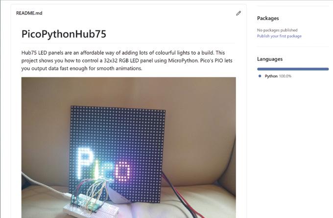
SIGN ANIMATED
Light up your living room like Piccadilly Circus
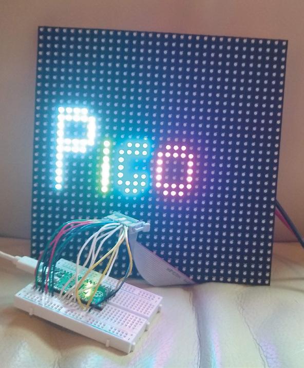
HUB75 LED panels provide an affordable way to add graphical output to your projects. They were originally designed for large advertising displays (such as the ones made famous by Piccadilly Circus in London, and Times Square in New York). However, we can use a little chunk of these bright lights in our projects. They’re often given a ‘P’ value, such as P3 or P5 for the number of millimetres between the different RGB LEDs. These don’t affect the working or wiring in any way. We used a 32×32 Adafruit screen. Other screens of this size may work, or may be wired differently. It should be possible to get screens of different sizes working, but you’ll have to dig through the code a little more to get it running properly.
The protocol for running these displays involves throwing large amounts of data down six different data lines. This lets you light up one portion of the display. You then switch to a different portion of the display and throw the data down the data lines again. When you’re not actively writing to a particular segment of the display, those LEDs are off.
There’s no in-built control over the brightness levels – each LED is either on or off. You can add some control over brightness by flicking pixels on and off for different amounts of time, but you have to manage this yourself. We won’t get into that in this tutorial,
MICROPYTHON
Before running this, you’ll need to get MicroPython up and running on your Pico. You can find details of how to do this at rptl.io/rp2040-get-started, in the MicroPython tab. If you’ve never used MicroPython before and want a quick introduction, take a look at our Getting Started guide in issue 39 (hsmag.cc/issue39).
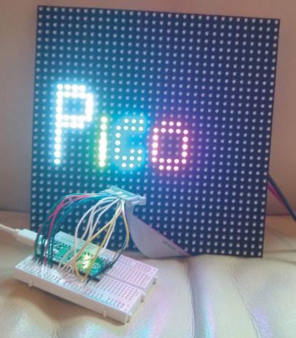
Raspberry Pi Pico Projects FEATURE 40 Above The most costeffective way to add 1024 RGB LEDs to your project
GOING FURTHER
The code we’ve created for this is a little rough around the edges, and needs some work. It works with the 32×32 Adafruit panels we’ve used in testing, and may work with some others. However, the code that sets up the data to be sent is far from perfect. If you’re familiar with HUB75 panels, or have some other sizes that you can test out, we’d love it if you got involved. Take a look at hsmag.cc/Hub75 and let’s try and get it into a more robust form. If we can get it into a useful state, we’ll wrap it up as a library so that it’s easy to reuse in other projects.
but if you’d like to investigate this, take a look at the box on 'Going Further'.
The first thing you need to do is wire up the screen. There are 16 connectors, and there are three different types of data sent – colour values, address values, and control values. You can wire this up in different ways, but we just used header wires to connect between a cable and a breadboard. See hsmag.cc/ Hub75 for details of the connections.
These screens can draw a lot of power, so it’s best not to power them from your Pico’s 5 V output. Instead, use a separate 5 V supply which can output enough current. A 1 A supply should be more than enough for this example. If you’re changing it, start with a small number of pixels lit up and use a multimeter to read the current.
With it wired up, the first thing to do is grab the code from hsmag.cc/Hub75 and run it. If everything’s working correctly, you should see the word Pico bounce up and down on the screen. It is a little sensitive to the wiring, so if you see some flickering, make sure that the wires are properly seated.
You may want to just display the word ‘Pico’. If so, congratulations, you’re finished! However, let’s take a look at how to customise the display.
The first things you’ll need to adapt if you want to display different data are the text functions – there’s one of these for each letter in Pico. For example, the following draws a lower-case ‘i’:
def i_draw(init_x, init_y, r, g, b): for i in range(4): light_xy(init_x, init_y+i+2, r, g, b) light_xy(init_x, init_y, r, g, b)
As you can see, this uses the light_xy method to set a particular pixel a particular colour (r, g, and b can all be 0 or 1).
You’ll also need your own draw method. The current one is as follows:
def draw_text(): global text_y global direction global writing global current_rows global rows
writing = True
text_y = text_y + direction if text_y > 20: direction = -1 if text_y < 5: direction = 1
rows = [0]*num_rows
#fill with black for j in range(num_rows): rows[j] = [0]*blocks_per_row
p_draw(3, text_y-4, 1, 1, 1)
i_draw(9, text_y, 1, 1, 0)
c_draw(11, text_y, 0, 1, 1)
o_draw(16, text_y, 1, 0, 1)
writing = False
This sets the writing global variable to stop it drawing this frame if it’s still being updated, and then just scrolls the text_y variable between 5 and 20 to bounce the text up and down in the middle of the screen.
This method runs on the second core of Pico, so it can still throw out data constantly from the main processing core without it slowing down to draw images.
LENS 41
Above The code for this is on GitHub (hsmag.cc/Hub75). If you spot a way of improving it, send us a pull request!
DISPLAY LIGHT
Trap some electric fireflies in a jar

Adding flashing lights to a project is a great way to make it a little more visually appealing, and WS2812B LEDs (sometimes known as NeoPixels) are a great way to do that. They have their own mini communications protocol, so you can control lots of them with just a single pin on your microcontroller, and there’s a handy library for Pico MicroPython that lets you control them.
First, you need to grab the library from hsmag.cc/PicoPython and copy the PY file to your Pico device. You can do this by opening the file in Thonny and clicking Save As, and then selecting your MicroPython device and calling it ws2812b.py
You create an object with the following parameters: number of LEDs, state machine ID, and GPIO number, in that order. So, to create a strip of ten LEDs on state machine 0 and GPIO 0, you use:
pixels = ws2812b.ws2812b(10,0,0)
This object has two methods: show() which sends the data to the strip, and set_pixel which sets the colour values for a particular LED. The parameters are LED number, red, green, blue, with the colours taking values between 0 and 255.
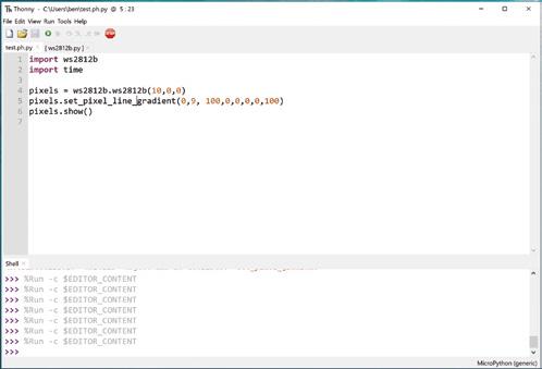
At the time of writing, there’s an issue using this library in the interpreter. The author is investigating, but it’s best to run it from saved files to ensure everything runs properly. Create a file with the following and run it:
import ws2812b import time
pixels = ws2812b.ws2812b(10,0,0) pixels.set_pixel(5,10,0,0) pixels.show() time.sleep(2) pixels.set_pixel(5,0,10,0) pixels.show() time.sleep(2) pixels.fill(0,0,10) pixels.show() time.sleep(2)
So, now we can light up some LEDs, let’s take a look at how to turn this into an interesting light fixture. We originally created the fireflies example in the WS2812B project for Christmas tree lights, but once
Raspberry Pi Pico Projects FEATURE 42
Above You can tweak the code to add more or fewer LEDs, speed it up or slow it down, and make it your own in whatever way you like
the festive season was over, we liked them so much that we wanted to keep them going year round. Obviously, we can’t just keep a tree up all the time, so we needed another way to display them. We’re using them on thin-wire WS2812B LEDs that are available from direct-from-China sellers, but they should work on other types of WS2812B-compatible LEDs.
For display, we’ve put the string of LEDs into a glass demijohn that we used to use for brewing, but any large glass jar would work. This gives an effect inspired by fireflies trapped in a jar. You can just download the code and run it (it’s in the examples folder in the above repository), but let’s take a look and see how it works.
The first part of the code sets everything up:
import time import ws2812b import random
bright_div = 20 numpix = 50 # Number of NeoPixels strip = ws2812b.ws2812b(numpix, 0,0)
colors = [ [232, 100, 255], # Purple [200, 200, 20], # Yellow [30, 200, 200], # Blue [150,50,10], [50,200,10], ]
max_len=20 min_len = 5
flashing = []
num_flashes = 10
You can change numpix , and the details for creating the WS2812B object, to whatever’s suitable for your setup. The colors array holds the different colours that you want your LEDs to flash (in red, green, blue
format). You can add to these or change them. We like the subtle pastels of this palette, but you can make it bolder by having more pure colours.
The max_len and min_ len variables control the length of time each light flashes for. They’re not in any units (other than iterations of the main loop), so you may need a little trial and error to get settings that are pleasing for you. The remaining code is what actually does the work of flashing each LED:
for i in range(num_flashes): pix = random.randint(0, numpix - 1) col = random.randint(1, len(colors) - 1) flash_len = random.randint(min_len, max_len) flashing.append([pix, colors[col], flash_len, 0, 1])
strip.fill(0,0,0)
while True:
strip.show() for i in range(num_flashes):
pix = flashing[i][0]
brightness = (flashing[i][3]/flashing[i][2]) colr = (int(flashing[i][1][0]*brightness), int(flashing[i][1][1]*brightness), int(flashing[i][1][2]*brightness))
strip.set_pixel(pix, colr[0], colr[1], colr[2])
if flashing[i][2] == flashing[i][3]: flashing[i][4] = -1 if flashing[i][3] == 0 and flashing[i][4] == -1:
pix = random.randint(0, numpix - 1) col = random.randint(0, len(colors)1)
flash_len = random.randint(min_len, max_len)
flashing[i] = [pix, colors[col], flash_ len, 0, 1]
flashing[i][3] = flashing[i][3] + flashing[i] [4]
time.sleep(0.005)
The flashing list contains an entry for every LED that’s currently flashing. It stores the LED position colour, length of the flash, current position of the flash, and whether it’s getting brighter or dimmer. These are initially seeded with random data; then we start a loop that keeps updating the display.
That’s all there is to it. You can tweak this code or create your very own custom display.
Above
There are some other methods in the WS2812B module, such as set_ pixel_line_gradient() to add effects to your projects
LENS
43
NOISE MAKE SOME
Adding beeps and boops to your Pico project
Pico’s PIO hardware can be used to handle fine-grained timing of I/O pins. This can be employed to handle high-speed data output (or input), but it can also be used to interact with our brains. Let’s take a look at how to use PIO for sound.
We’ve created a library for simple square-wave sounds at hsmag.cc/PicoBuzz. There are a few files there. PIOBeep.py is the module we’ll be importing,
so you need to download this and transfer it to your Pico (open it in Thonny, then use File > Save As to save it to Pico (use the same file name)). Once it’s on there, you can import it in your programs.
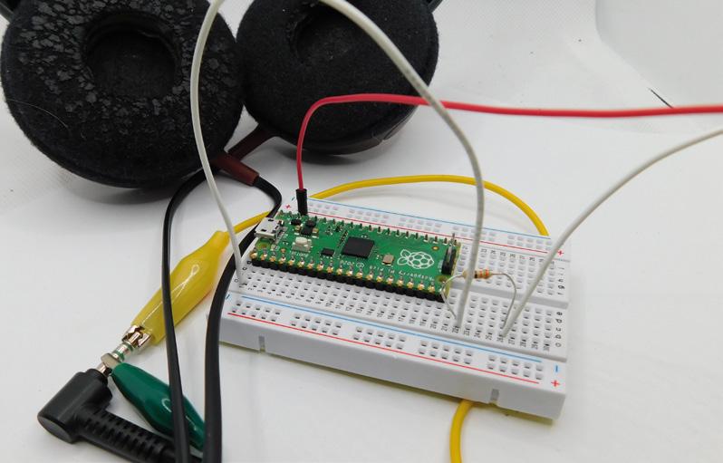
To get sound out of Pico, you need to attach a speaker or headphones. The easiest way of doing this is using crocodile clips on a headphone jack. On ordinary headphones, there should be three metal contacts – you’ll need to connect to the tip and the base. This will only output sound to one ear. If you want a more permanent setup, you could add a headphone jack socket to let you easily plug in and out, or you could use a portable speaker with a jack.
It’s hard to know exactly how much current headphones will draw, and it’s better to be safe than
Raspberry Pi Pico Projects FEATURE 44
Right If you create your own songs, let us know! Tag us on social media, or email hackspace@ raspberrypi.com
sorry, so adding a 250–300 ohm resistor, in series with the headphones, should prevent any damage to either the headphones or the Pico. This may make the sound quiet; you can try dropping the value of this resistor if it’s too quiet. You may be able to get away without using a resistor at all, but don’t blame us if this damages your Pico, your headphones, or your ears.
That’s the hardware set up, let’s now look at the software.
As a simple test, type the following into the MicroPython interpreter:
>>> import PIOBeep
>>> beeper = PIOBeep.PIOBeep(0,0)
>>> beeper.play_pitch(10,1,400)
The first line imports the module. The second line sets up the PIOBeep object with state machine 0 on pin 0. You can create up to eight different PIOBeep objects at a time, all outputting on different GPIO pins using the state machine IDs 0–7 as the first parameter here. The final line will play a ten-second note at 400Hz, with a one-second pause at the end.
That’s the basics of how to use our little buzzer library, but there is a slight optimisation we can use. The module needs to convert the frequency you want to play into the value that’s passed to the PIO program. We can do this on the fly as we did above, but if we’re going to play a note multiple times, it's slightly quicker to pre-compute it. We’ve done this in the following code which plays the first line of Happy Birthday To You:
import PIOBeep from time import sleep
beeper = PIOBeep.PIOBeep(0,0)
notes = [392, 440, 494, 523, 587, 659, 698, 784]
HIGH QUALITY
We’re using PIO in a very rudimentary way here – just creating a simple square wave which gives beeps and boops. PIO can actually do far more nuanced audio than this using pico_audio. However, this is currently only available in the C SDK, and is still a bit experimental. We’ll come back to it in a future issue, but if you want to have a sneak peek at what’s possible, take a look at PicoPicoSynth (hsmag.cc/PicoSynth). Note, this may or may not compile when you access it, as the API is changing from time to time, and the author may or may not have caught up with the current changes, but it should give you an idea of what’s possible.

notes_val = [] for note in notes:
notes_val.append(beeper.calc_pitch(note))
#the length of a semi-quaver, the shortest note in the song note_len = 0.1 pause_len = 0.05
while True:
beeper.play_value(note_len*2, pause_len, notes_ val[0])
beeper.play_value(note_len, pause_len, notes_ val[0])
beeper.play_value(note_len*4, pause_len, notes_ val[1])
beeper.play_value(note_len*4, pause_len, notes_ val[0])
beeper.play_value(note_len*4, pause_len, notes_ val[3])
beeper.play_value(note_len*8, pause_len, notes_ val[2])
The full code (including all lines) is available at hsmag.cc/PicoBuzz
That’s the basics of playing square waves with PIO. There are lots of ways you could expand this. The C SDK provides far more power for creating audio (see box). Alternatively, you could create a simple resistor DAC using two or more GPIO pins, and use the PIO program to create different waveforms. This program is blocking, meaning that while you’re waiting for the note to play, you can’t do other processing. This makes it simple to use for playing tunes, but if you want to use it for notifications, it’s not optimal. Since no processing is actually being done while the PIO program is outputting sound, you could use timers to turn the state machine on and off when you want. Alternatively, you could dedicate one processing core to playing the sound, while the other core does whatever other processing you need.
Above
Crocodile clips are great for testing, but consider adding a jack socket if you want to use this long-term
LENS 45
Raspberry Pi Pico Projects
FEATURE
PICO OVERCLOCKING YOUR
Push your Pico to its limits
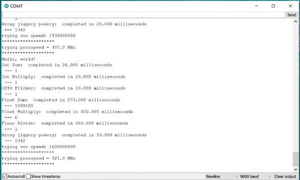
If you look at the datasheet for the RP2040 – the processor at the heart of your Raspberry Pi Pico – you’ll see that it runs at up to 133MHz. This is sort of true. The process for making silicon chips doesn’t make them all exactly the same. There are slight differences between any two integrated circuits that come out of the same foundry, and this means that some chips will work when running faster than others.
When Raspberry Pi says that Pico runs at 133MHz, what Raspberry Pi's engineers are saying here is that they will guarantee that it will definitely run at 133MHz. Many Picos will run faster than this, and a few will run much faster than this. Let’s take a look at how you can
Obviously, we’ll need some code so that we can see just how fast it’s running at. See our hsmag.cc/SpeedRmp. It’s a very simple benchmark that pushes the processor to do particular types of operations over and over again. For example:
int int_sum() { int y = 0; for(int z=0; z < LOOPS; z++)
{ y = y+z; if(y>1000000) { y=1;} } return y;// print so the loop isn't optimised away }
This is all wrapped in some simple code to get it all working: int main() {
vreg_set_voltage(VREG_VSEL); sleep_ms(10); int start = 0; int end = 0; int loops = 1000100; int y = 0; float y_float = 0;
uint32_t vco = 600000000; uint32_t crystal_freq = 12000000; float procspeed = 120;
volatile float z; volatile float a = 1.1;
int div1 = 5; int div2 = 1;
int step = 6;
JUST RUN THE CODE
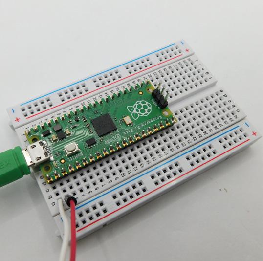
If you just want to know how fast your Pico will run and don’t care too much about how to push it to its limit, then you can download a UF2 file with the code on it from hsmag.cc/SRReleases. Flash this to Pico, and you should be able to see output on the serial port.
46 Below If you'd rather get data out of the UART on pins 0 and 1, use version 0.2
SERIAL PORT
This software sends information to the default UART, which can be set to transmit over USB or GPIO. The easiest option is to use USB (which is how it's set up in the CMake file).
Once you've flashed the UF2 file onto your Pico, it will run automatically. You'll need a serial port monitor to read the output. If you use the Arduino IDE for programming other boards, you can use the included serial monitor. There are other options on the getting started guide at hsmag.cc/OdxgkP
sleep_ms(10);
stdio_init_all();
//sleep ten sec to let you connect to uart sleep_ms(10000);
printf("Pico Speed test\n");
printf("let's see how fast your pico can go ...");
while (true) { printf("Hello, world!\n"); time(int_sum, "Int Sum: ");
//run other benchmarks
vco = vco+(step*crystal_freq); //increase at multiples of the crystal oscillator
procspeed = (vco/(div1*div2))/1000000;
printf("trying vco speed: %d\n", vco);
printf("********************\n");
printf("trying procspeed = %0.1f MHz\n", procspeed);
printf("********************\n");
set_sys_clock_pll(vco,div1,div2);
sleep_ms(100); } return 0; }
The first thing we do to give the RP2040 the best chance of running fast is to set the voltage as high as possible. This is done in two lines:
#define VREG_VSEL VREG_VOLTAGE_1_30
vreg_set_voltage(VREG_VSEL);
By default, the RP2040 runs at 1.1 V, but you can set it to anything between 0.85 and 1.3 V in 0.05 V increments. Since we’re not worried about temperature or power consumption, we’ve gone straight in with the highest voltage. This may reduce the life expectancy of your Pico. You can try running this at lower voltages if you want to keep your Pico alive for as long as possible and not push it to its limits.
Changing the clock speed is done with: set_sys_clock_pll(vco,div1,div2); setup_default_uart();
The set_sys_clock_pll() function takes three parameters: the Voltage Controlled Oscillator speed and two dividers. This sets the system clock speed to VCO / (divider1 × divider2). You can control any of these to get a wide range of frequencies, but we keep the dividers the same and increase the vco speed.
This is the basics of how to overclock your Pico. You should now know how fast your Pico can run, and how to tweak the settings, should you need to use the overclocking in your own projects.
COMPILING THE CODE
You’ll need the Raspberry Pi Pico C/C++ SDK setup to compile this code. See rptl.io/rp2040-get-started for details of how to do this. Once that’s done, you can tweak whatever you like and recompile the code with your own options. If you don’t want to go through setting up the C SDK, take a look at the 'Just Run The Code' box.
LENS
Below This test Pico can run at 307MHz – well over twice the so-called maximum speed – but some can go much faster 47
INSPIRATION OTHER
Our pick of projects from around the web
Raspberry Pi Pico has only been out for a month, but we've already seen some great projects popping up on pages around the web. Here are a few of our favourites at the moment, but we'll keep scanning the internet for new and exciting Pico projects.
What have you been up to? If you've created something that you'd like to share, let us know at hackspace@raspberrypi.com or @HackSpaceMag on social media. We can't wait to see what you get up to with this tiny, powerful device.
Is there anything you'd like to learn how to do? Get in touch with us about what Pico skills you'd like to learn and we'll put the finest minds (well, the finest we have available) to work on it.
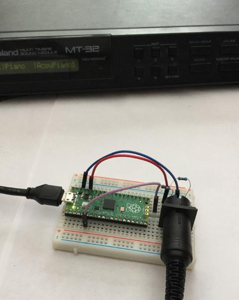
MIDI MUSIC
You can hook up your Pico to a MIDI-DIN port and use it to control your favourite MIDI hardware. This example is from DIYElectronicMusic, and you can find full instructions for how to play Bach’s Prelude in C Major at hsmag.cc/PicoMusic. It outputs notes using Pico’s UART, and all you have to do to play a different tune is arrange the notes in a different order.
Raspberry Pi Pico Projects FEATURE 48
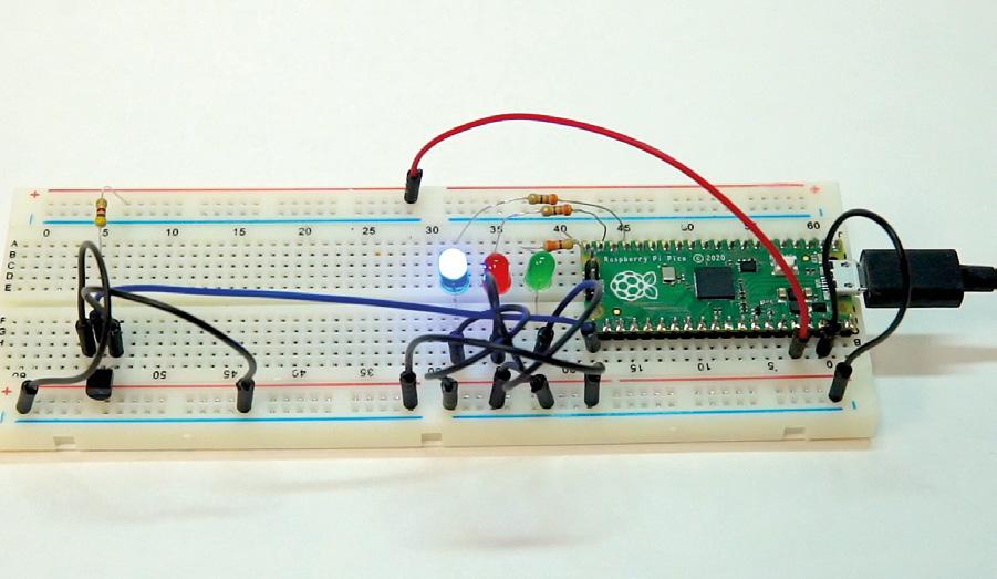
Little babies are fragile things. They need cuddles and are obviously an excuse for a new gadget or two. Jeff, being in possession of both a newborn baby and a Raspberry Pi Pico, decided to use the latter to protect the former. He used the in-built temperature sensor on the Pico to read the temperature in the baby’s room and lit up a few lights to let him know if the temperature was safe for the baby to sleep in (getting too hot or cold can increase the risk to newborns). Take a look at his video at hsmag.cc/TempAlarm for more details on his build.
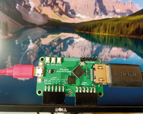
RP2040 – the microcontroller at the heart of Pico – is capable of phenomenal I/O transfer speeds. Thanks to DMA and Programmable I/O, you can throw data out at speeds not usually possible with a microcontroller. However, just how fast can it go? Can it drive 720p30 video over HDMI (that’s 372Mbps of data transfer)? Luke Wren, one of the developers of RP2040, decided to find out, and it turns out that it can. In fact, not only can it drive one HDMI screen, it can drive two. Take a look at hsmag.cc/PicoDVI for all the details.
LENS
PICODVI
ALARM 49 hsmag.cc/FreePico Get a FREE PICO when you subscribe from £10
TEMPERATURE


Subscription will continue quarterly unless cancelled hsmag.cc/FreePico SUBSCRIBE TODAY Get three issues plus a FREE Raspberry Pi Pico delivered to your door FOR JUST £10 UK offer only. Not in the UK? Save money and get your issue delivered straight to your door at hsmag.cc/subscribe See page 66 for details.


SUBSCRIPTION hsmag.cc Issue #38 January 2021 RASPBERRY PI XMAS LASER ETCHING Microcontrollers go modular The best festive makes RubenBringing craft and digital design MICROMOD + Jan. 2021 Issue #38 £6 Issue #38 January 2021 + + hsmag.cc Issue #39 February 2021 Issue #39 February 2021 Raspberry Pi Pico FREE DUAL-CORE MICROCONTROLLER LOW-COST HIGH-PERFORMANCE FLEXIBLE I/O A NEW MICROCONTROLLER BOARD FROM RASPBERRY PI INTRODUCING 1. 2. 3. 4. 5. + 6. 7. IN GNDOUT 8. 9. 10. 11. PICO RASPBERRY PI hsmag.cc Issue #40 March 2021 Is this your next soldering iron? Pinecil PROJECTS Things to make with your $4 microcontroller Mar. 2021 Issue #40 £6 Add encryption to MQTT IOT Security How citizen scientists are looking after these lovely little honey-makers BEES BEES Screen printing in the digital age Laser cut printing ALUMINIUM FOIL CNC CROCHET LEDS 44% SAVE SUBSCRIBE on app stores From £2.29 Buy now: hsmag.cc/subscribe Free Pico with print subscription only
How I Made
A RASPBERRY PICONTROLLED CNC PLOTTER
Join the ranks of Plotter Twitter with salvaged components
By Stratos Botsaris
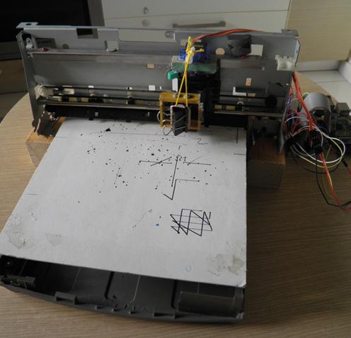
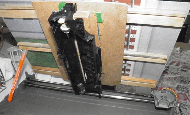
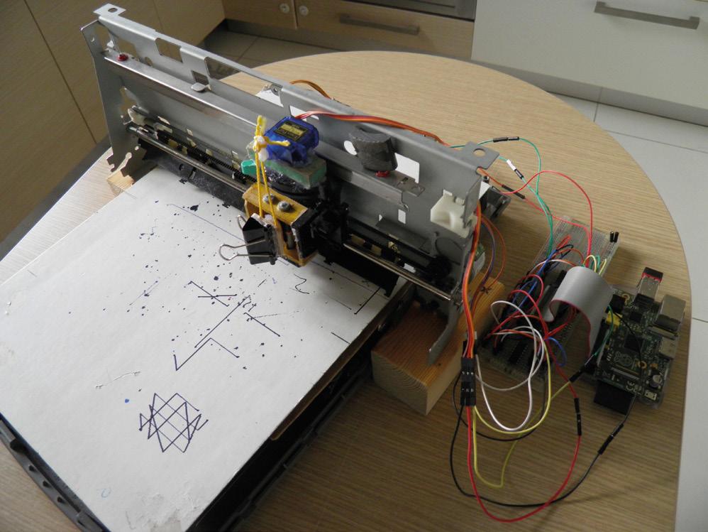
Behold, a CNC plotter which is controlled by a Raspberry Pi and can draw an image on an A4 paper.
many CNC plotters, but this one is special because I designed both the hardware and the software myself. I have assembled its hardware by using recycled parts from an old scanner and a printer.
Moreover, I have written the Python software that translates the G-code into actual physical drawings. But first: what and why?
COMPUTER NUMERICAL CONTROL
A CNC is a machine whose movements are controlled by a computer through a process known as computer numerical control. Some examples of common CNC machines are milling machines, 3D printers, laser cutters, and many others. I had seen people creating and using CNC plotters and always wondered how
these machines work. Especially the way the CNC machine translates the G-code instructions into movement that drives the stepper motors. I wanted to find out the internal workings.
Moreover, most of the CNC plotters were created with the use of the Arduino board. That’s the reason that I wanted to try it with the Raspberry Pi and see if it is possible.
So I started experimenting with a stepper motor and the Raspberry Pi. Fortunately, I was lucky enough to have salvaged one stepper motor from an old printer and another one from an old scanner. In the beginning, I had to find out how stepper motors work and how to connect one to the Raspberry Pi. Then I tried to drive the stepper motor by writing a small program in Python and running it on the Raspberry Pi. Once I managed to make this work, I got very excited, and this gave me the push to continue with controlling two stepper motors at the same time. This was
FEATURE
52
How I Made: A Raspberry Pi-controlled CNC plotter
the most tricky part because I had to find a way to move the two stepper motors in parallel if I ever wanted the CNC plotter to draw a diagonal line.
I tried several algorithms in Python, but eventually, the simplest one worked as I wanted.
HOW DO COMPUTERCONTROLLED MACHINES WORK?
For a CNC machine to make precise movements, it needs to know where and how quickly to move in twodimensional space.
These movement instructions, or toolpaths, are called G-code. G-code is created in a CAM program which produces a file.

53 LENS
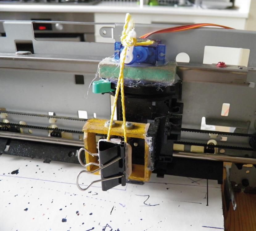
Left Sometimes a simple approach is best, like this bulldog clip
Below
The X-axis stands above the Y-axis on some wooden blocks
How I Made: A Raspberry Pi-controlled CNC plotter

Then an interpreter is needed to read through the G-code from the file and execute each movement instruction. This means translating each instruction into movement for driving each stepper motor.
WHAT IS A CNC PLOTTER?
A CNC plotter is basically a 2.5 axis CNC machine. It has a stepper motor on each of the X and Y axes and a servo motor at the Z-axis. A pen is connected on the X-axis, and the Z-axis is used to move the pen up and down.
As the name suggests, the CNC plotter draws or plots a drawing by giving it a number of instructions. These instructions are called G-code – they’re included in a file with the extension ‘.GCODE’.
I use the Inkscape software program to convert an image to G-code. Then I use this file in my Python program, which executes the G-code line by line and translates it into movements for the stepper motors on each axis. As a result, the plotter can draw the image on paper.
WHAT IS A STEPPER MOTOR?
A stepper motor, also known as step motor or stepping motor, is a brushless DC electric motor that divides a full rotation into a number of equal steps. As long as the motor is calibrated to the application for torque and speed, the user (or more usually, control software), can move the motor’s position to a given position without the need for an external position sensor.
The absence of a sensor is the big difference between a stepper motor and a servo. With a stepper motor, you tell it how far you want it to try and turn. With a servo, you tell it what position you want it to be in, and it will try and do it. While the servo’s sensing might sound useful, in practice, it means that the accuracy is defined by the sensor, which is often not as accurate as using a stepper motor’s approach.

FEATURE 54
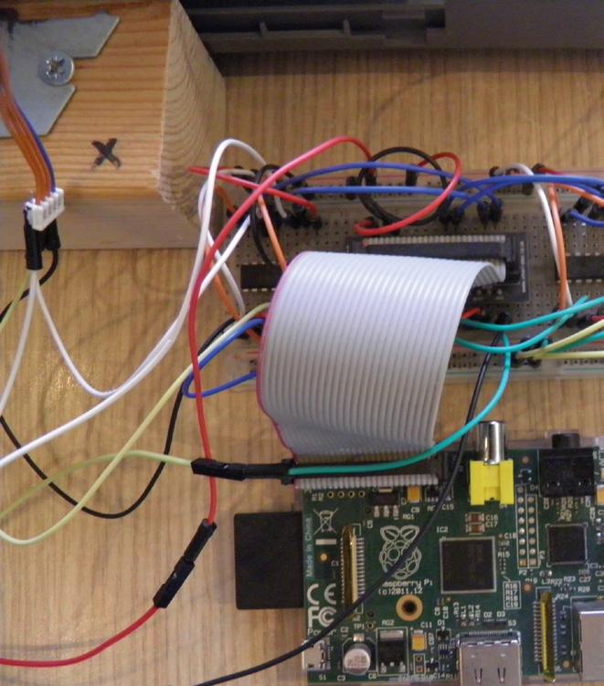
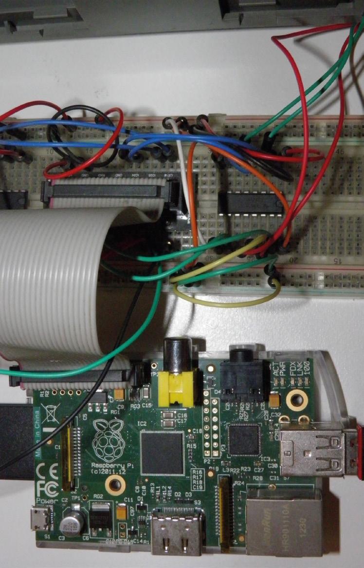
Above and right Using driver chips rather than modules can help you save costs, but it does mean that you’ll need a breadboard
Below
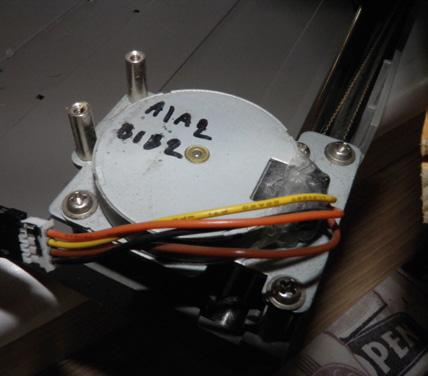
motors are
by
PARTS REQUIRED:
• Raspberry Pi 1 Model B, Revision 2
• Raspberry Pi accessories including power supply cable, SD card, and WiFi dongle
• Breadboard and cables
• Chassis from an old scanner, including the drive system with the stepper motor and the timing belt. This is the CNC Y-axis which moves back and forth
• Chassis from an old printer including the drive system with the stepper motor and the timing belt. This is the CNC X-axis which moves left and right
• Two L293D ICs – motor drivers for controlling each of the two stepper motors
• Mini servo motor
55 LENS
Right The wiring did get a bit messy towards the end!
Stepper
controlled
four wires, and rotate in a fixed number of steps per full turn
How I Made: A Raspberry Pi-controlled CNC plotter
I implemented the software program myself because I wanted to find out the internal working of a CNC plotter

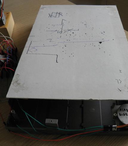
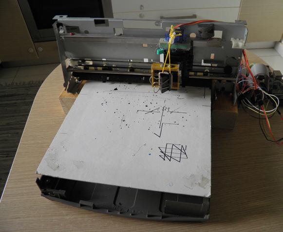
As you can see from the photos, the X and Y axes of the plotter can be taken apart, moved easily to another place, and then reassembled again.
It took me around three years to build the whole thing, but I was doing it parttime, mainly during holidays and some weekends. First, I assembled the hardware part, and then I implemented the software program. All stages included a lot of testing.
HOW MUCH DID IT COST?
I wanted to minimise the cost as much as possible in order to find out how cheap such a project can be.
That is the reason I reused parts from an old scanner and a printer for the hardware part. Also, I used L293D chips instead of an L298D motor driver board which is more expensive. So, the only cost was actually the Raspberry Pi and its accessories, and I owned these anyway.
Finally, I implemented the software program myself because I wanted to find out the internal working of a CNC plotter. So I would say the only cost to me was time, which I enjoyed spending on this project!
FEATURE 56
Above The Y-axis sits under the X-axis as a separate part
Above Salvaging motors meant they came with ready-made mountings

Left
Looking at the parts gives me flashbacks to memories of getting reluctant PC hardware to work
Below The only decision now is what to draw
57 LENS
INTERVIEW
ofprivate Bees
Interview
The private life of bees
The more useful, friendlier cousin of the wasp
You may think you know bees from their sterling work producing honey. But there’s more to them than that.
On their quest for nectar, the sugary substance that they turn into honey, bees pollinate flowers – including those of most fruit and vegetable plants. Without bees, food harvests would either be dramatically smaller or non-existent, causing (at best) food prices to go up or (at worst) many millions of people to starve to death. We need to look after bees, understand them, and find out what they’re up to.
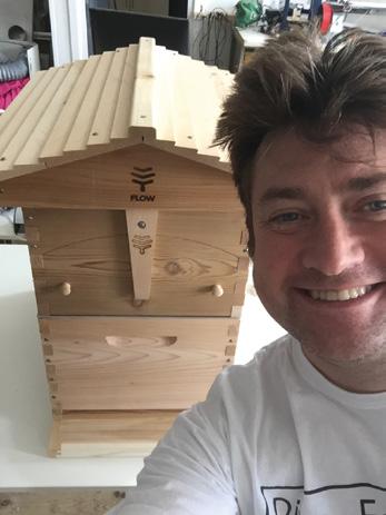
That’s why we caught up with Andrea Ku and Alex Lennon, who have teamed up to monitor a beehive in the centre of Liverpool – with cheap, off-the-shelf hardware that anyone can get hold of. And if you want the multimedia immersive experience while you’re reading this, you can watch and listen to the bees in question at mybees.co.uk
The private life of bees
58
private Bees

59 LENS
Above Andrea Ku looks after 35 beehives in Liverpool and on the Wirral
Left Alex Lennon makes smart objects talk to the internet and each other
Image credit:
Joel Goodman
INTERVIEW
ofprivate Bees
HackSpace First of all, who are you and how did you get into bees?
Andrea Ku I’m originally an artist, and I’ve also been keeping bees for ten years. I’m also a trained landscape architect. I work a lot from the ground up to improve nature, mostly in Merseyside, so I work with school groups, community garden groups – small groups who are going to use areas of their gardens or parks or whatever.
The most effective way I found people were engaging with their landscape was through bees and bee-keeping. I’ve been teaching bee-keeping now for the last seven years, for ages 4 up to 85.
In bee-keeping there’s a lot of data that you can collect. For example, if there’s a new queen, if the old queen is dead, or missing, or the bees have killed her, down to temperature, time of year; there’s so much to keep a note of. And I was really thinking, how can I turn this into a datadriven art piece?
I gave a talk at DoES Liverpool [the incredibly productive local makerspace] about two years ago, and this project came from there. Alex was on one of my bee courses last year, and we’ve been in touch since then.
I don’t know any tech. I feel like I’m eavesdropping on the magic circle, hearing some of these things.
Alex Lennon I’m helping out with the tech side of things, mainly because I’ve always been interested in bees, but never really knew how to begin. I’m having a great time because I’m learning about all this stuff as I go along.
I attended an online course that Andrea was running – we got talking about what would be useful and interesting to do. It seemed like there was a two-pronged approach. One was that we wanted a lot of sensing and telemetry.
My background is embedded systems, I’ve been doing that for 20, 25 years. That’s all about little black boxes, communication, sensing, maybe a little bit of control. It’s meat and drink to me.
And there’s a lot of interesting things that we can learn from the data. But it’s not all that sexy – numbers don’t really pull people in terribly well.
So the other line of attack was putting a camera in there, and watching and listening to what the bees are up to. With my commercial hat on, I design and manufacture embedded devices, but it seemed a lot more sensible for this project, which is a completely opensource project – we want people to be involved in this and take what they want from it – it made more sense to use offthe-shelf devices, and Raspberry Pi is the obvious choice for that. So we started with a Raspberry Pi 4 in there.
It’s worth just noting that we use something called Balena. Without going too deep into it, Balena is run by a lovely bunch of people who have taken Docker cloud containers and put them into embedded devices. That enables us to manage the Raspberry Pi in the beehive remotely really easily, update it, and see what’s going on with it. It’s a real nice way of doing things. So there’s a Raspberry Pi running Balena, networked up, and the lovely people at DoES Liverpool where Andrea has three hives on the roof, in central Liverpool, and we’ve got one of those connected via a Power over Ethernet connection into DoES Liverpool. They’ve been a huge help in terms of getting us wired up, infrastructure, bandwidth – those sorts of things.
In the hive, we grabbed an IR camera. It’s a Raspberry Pi Camera that connects directly on to the board.
It’s also got two infrared lights that are light-level sensitive. In the hive, those lights are on, and that’s what allows us to capture the images of what the bees are up to.
HS Doesn’t that disturb the bees, having a light on them all the time?
AL Bees don’t see down into the infrared spectrum; they actually see higher than we do, so they see the things that we see but they also see up into ultraviolet.
Andrea showed me some images of flowers lit with UV and they look like targets, or landing zones.
What we’re doing with the infrared cameras, they don’t see that, so it doesn’t disturb their routines.
Similarly, we don’t want to use the WiFi on the Raspberry Pi. We don’t know, but we think that the radio emissions may affect the bees, so we want to limit that as much as possible. It’s part of the learning experience. We’re very much learning on the job, and we’re very cognisant of not going in and causing trouble for these hives, because that’s the opposite of what we want to do.
So, we’ve got a camera and a microphone in there, and that’s livestreaming 24-7 onto the internet. We’ve got a little site that we put together, and you can go in and see what the bees are up to at any time.
With the sensing, we just thought, what can we do? So, we’ve got things like temperature, pressure, humidity. We’ve also got two different kinds of particulate sensors, which are monitoring for a couple of different sizes of particulates, which could be pollen or it could be pollutants, and we’ve got some sensors monitoring for different kinds of gas.
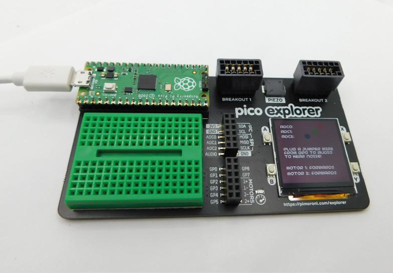
HS I recognise some of the hardware you’re using from these pictures…
AL When we started out with this, I was cobbling together individual different sensors that I was picking up from here and there. It was working fine – these are all I2C sensors that we’d connected up to Raspberry Pi. But, as time went on, I fortuitously came across a lovely little thing that Pimoroni has released called the Enviro+ board. It’s beautiful, and it’s lovely. They’ve integrated all the things that I was cobbling together in I2C with loads of wires all over the place, into one add-on.
So, the core of what we’re doing at the minute is all of the Enviro+ sensors and the add-on particulate sensor.
Part of this is the question ‘can other people build upon this work and
The private life of bees
60
private Bees

Below Bees collect food (and pollutants) from a wide area – up to five miles from the hive

recreate what we’re doing in this hive, in other hives’? The Enviro+ board happily sits on a Raspberry Pi Zero, of course, so rather than trying to put the Enviro+ on Raspberry Pi 4 as well as the higher-end audio-video stuff, what about if we have a separate sensor setup?
So, we’ve got a separate Raspberry Pi Zero which is running the Enviro+, and that’s connected off the USB of Raspberry Pi 4. It’s going through Raspberry Pi 4 to do all its telemetry reporting, so there are two different systems coexisting there.
You could take away Raspberry Pi Zero and just have that in a hive, which is probably the next thing we want to do, because you’re not going to wire Ethernet into hives all over the place.
Now we’re looking at battery power and LoRa communications, and sending data from hives out in the middle of nowhere. That way, we can begin to look at these different sensor data sets and how they range in different locations. We’ve got all sorts going on around Liverpool. There’s a big port expansion going on, so there are a lot more lorries than normal coming through. Can we look at what that’s doing to our city?
The bees are like remote sensors. They’re going all over the place and bringing things back to the hive. They’re showing us what’s going on in the local environment. As long as you can read it, you know what’s happening.
HS I think we need a bit of background into what bees do and why they’re important.
AK There are three types of bees in England. Honeybees, bumblebees, and solitary bees. Except for solitary bees, bees are social insects. They live in a group, there’s no social authority – they all work together. Honeybees are a perfect example of everyone working together. I really like that ethos. The bees work together to make something better. Bees have come from ants, which are also social, and ants have come from
ofprivate Bees
Below Bees thrive in urban environments as well as the countryside
termites. It’s a honeybee hive that we’ve got monitored. People don’t really keep bumblebees because there’s nothing much you can get out of it – apart from the growing appreciation of the pollination function that bees perform.
One in three mouthfuls of food we eat has been pollinated by bees. Fruit, vegetables… it’s essential.
HS That’s why it seems such an odd thing to be reintroducing neonicotinoids [a type of pesticide that’s toxic to bees, and banned in the EU] in Britain.
AL One of the things we’re interested in is can we monitor that? Can we monitor pollution, what the bees are bringing into the hives? That’s very much part of what we’re trying to do.
There was a really high level of pollution one Saturday, just after Christmas, and all of a sudden, all the particulates went really high. We don’t know what it was. Maybe container ships – if the wind changes, it can waft a load of diesel emissions from the container ships going up and down the Mersey.
We don’t know. But we’re at the point now where we’re capturing reliable data from the hive, we’re graphing that, and the next part of this project is: how do we look at that? How do we understand what the data means in terms of the environment?
One of the things Andrea was explaining to me was sentinel hives. Bees are so important to the ecosystem, and in places like Liverpool, because we’ve got so much port traffic coming in and out from other bits of the world, you’re getting little animals coming as well. There are a number of different parasites that bees have real problems with. Some beekeepers sign up to one of the agencies of DEFRA [the Department for Environment, Food and Rural Affairs] to be monitored. They check if everything’s OK, and in that way you can track the progress of parasites across the UK and across the world.
AK It’s called the National Bee Unit. The UK has a local bee inspector designated to each region. I’ve got three apiaries that are sentinel apiaries. That’s because bees in port cities are at much higher risk of disease than in the rest of the country.
HS What are they looking for?
AK The two big ones that we don’t want are the Asian hornet and the small hive beetle.
There’s the European hornet, which is native, that’s like a big wasp. But because we’re getting a lot of containers coming in from China, there’s a chance that an Asian hornet queen could make its way over here and establish a colony. Those prey on honeybees – they get into the hive, kill
” Can we monitor pollution, what the bees are bringing into the hives?
private Bees
the bees, and eat the honey; they’ll quickly destroy a weak hive.
The other one is the small hive beetle. The nearest that’s been found to England is southern Italy. It’s from Africa originally; it has made its way around the world, because in southern Italy there are successful bee breeding programmes; people like Italian bees, they’re small, they look good, they’re hard-working, they produce loads of honey.
They’re being sold all around the world, and there’s an issue with the small hive beetle in Italy. It’s not to say we haven’t got it in England, it’s just never been identified. Wild colonies in the middle of nowhere might have it.
That’s a big one because that could devastate the agricultural pollination service as well.
In sentinel apiaries, the local bee inspector will come along three times a
”
year. They’ll check the hive, check for all sorts of pests and disease.
I’ve got four apiaries, north, central and south Liverpool, and there are docks within flying range of all these. And my fourth is in Ness Botanic Gardens on the Wirral – because it’s a botanic garden, they get specimens from all over the world. Their plants go in quarantine for two weeks, but a small hive beetle can survive for longer than that.
But not a lot of bee-keepers like the idea of the local bee inspector checking them, because they think ‘there’s nothing wrong with my bees – I know everything there is to know’, or else at the other end of the spectrum, they’re ashamed of the state of their hives.
HS Have you had the data long enough to establish any trends?
AL It’s one of those things. Because it’s one of the more fun and interesting projects, it’s got to coexist along with the commercial stuff.
We’ve been talking about this for a while now, and what’s pushed us was that we needed to get into the hives before the end of last year, before the bees have started settling down and become more dormant. We couldn’t have been taking the tech out and putting it back in and that kind of thing, as there was a bit of a rush. So it’s there now, but we’re not at the point where we’re looking at trend information. The initial bit has been making sure it works!
It’s pretty reliable now, so we’re at the point where we’ve got this data that’s being captured into a database, and that will build up over time.
The other thing is that we’re keeping the data open. We want people to come and join us, take the data, and do things with it. We’re not precious about that. There are a couple of things that we’re interested in: particulates and pollution, and that sort of thing.
There’s also … so you’ve got bees swarming, and your queen in the hive,
63 LENS
INTERVIEW
and as more queens are born, that preps the hive to break apart. Then there’s a swarm, and the swarm will leave and find a new hive.
We discovered that you can identify queens within the hive because of the noise they make. It’s early days, but we’ve got microphones in there, so this led us to question: can we use artificial intelligence and machine learning techniques to listen to the queens and do swarm prediction?
You can evaluate the health of the hives from the noise they’re making, the numbers of the queens, all these kinds of things. There are much cleverer people than me who will have ideas on how to do that, and it would be great to talk to them.
It’s the same with analysis of the video, because you see them at night-time all piled together for warmth. It feels like you could do some good analysis with that too.
When the bees are in the hive doing their own thing, it’s quite a meditative experience, It’s quite relaxing. You can hear the environment, you can hear cars going up and down the road. You’re listening into the bees sharing our surroundings.
HS You mentioned opening the data. Do you want other people to create data with you as well? If someone else were to put sensors into their hive, would you be interested in working with them?
AL For me, this is a lot of fun. I’m doing really interesting stuff that actually has a positive environmental and social impact. I’m learning as I go along, and I don’t really know where this is going to go. I’m really keen to engage with people who have ideas.
AK I love the idea of turning data into a piece of work: if you can record the musical notes that the bees are making,
you could turn it into music. The noise the queen makes is called piping, and it’s in A-sharp. Even the temperatures could be turned into music.
If you listen to the bees now in January/February time, they’re clustering, so they make a low hum. In the height of summer, when the colony is at its peak numbers, the sound is completely different. Even the presence of male bees changes it. There are no male bees in the hive at the moment, because the females will have kicked them out in autumn. The males know their purpose in life is to mate with a queen. The workers are all female. After the males have mated, the female bees kill the males, they kick them out of the hive. But the males are distinguishable because they’re so loud.
Before Covid, I was preparing to teach a lesson to some blind students, so I spent some time working with the bees with my eyes closed. You can tell from the sound when they’re happy, when there’s a drone nearby, when there’s a new queen. Turning all that into some sort of art piece is something that I’d very much like to do.
There’s a group of bee-keepers in Cumbria, a junior school that teaches bee-keeping to kids, but they do it to such a really high level. The kids are so advanced when it comes to beekeeping. They’re very progressive and forward-thinking.
The typical demographic of bee-keepers is a retired man in his 70s. I go to bee-keeping conventions and there’s no-one else there under 45. But in this school, they’re really progressive, and a lot of older bee-keepers don’t like it; they’re a bit snidey with the tech stuff. It would be great to make a tech pack that other bee-keepers can plug and play into their own hives, and you can collect the data not just about the bees, but about your environment. We need to make sure that more people are interested in beekeeping – its science, craft, and tradition, and it’s important for the planet.
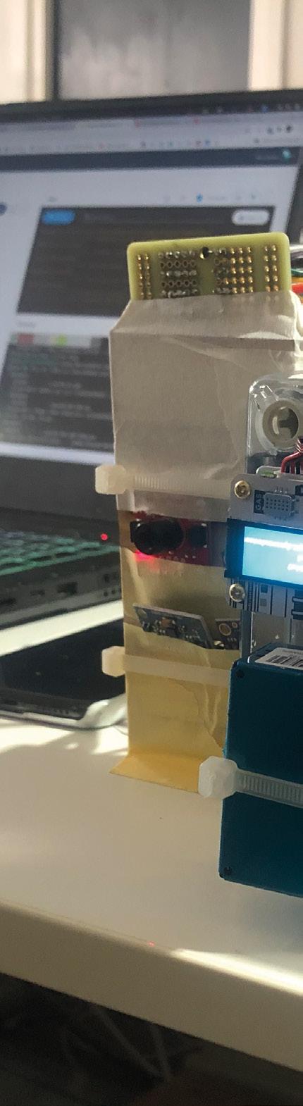
ofprivate Bees
The private life of bees
64
Right Pimoroni’s Enviro+ HAT (among some other components) is put to good use in the hive setup
private Bees
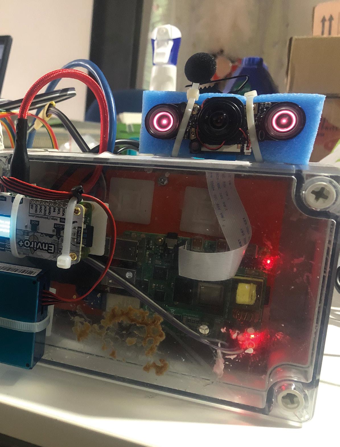


Get started with on Raspberry Pi Pico MicroPython
Learn how to use your new Raspberry Pi Pico microcontroller board and program it using MicroPython. Connect hardware to make your Pico interact with the world around it. Create your own electro-mechanical projects, whether for fun or to make your life easier.
Set up your Raspberry Pi Pico and start using it
Start writing programs using MicroPython

OFFICIAL RASPBERRY PI PICO GUIDE
Control and sense electronic components
Discover how to use Pico’s unique Programmable IO
Available now: magpi.cc/picobook
ALUMINIUM FOIL
Keep your builds fresh for longer

Mayank Sharma
@geekybodhi
Mayank is a Padawan maker with an irrational fear of drills. He likes to replicate electronic builds, and gets a kick out of hacking everyday objects creatively.
Like most things found in the kitchen, the aluminium foil is also a versatile tool that can be put to all kinds of uses. As per some estimates, about 75 percent of aluminium foil is used for packaging and household foil, while the rest is used in industrial applications.
Aluminium foil’s popularity as a packaging material is due to it being non-toxic and impermeable to water vapour and gases. These properties help it extend the shelf life of eatables, while taking up little extra storage space, and at the same time generating less waste than many other packaging materials.
In fact, aluminium foil saves far more resources than it consumes during production and, according to some estimates, more than half of aluminium packaging in Europe is recycled.
Aluminium foil is made from an aluminium alloy which contains over 90% aluminium. This is why
“The manufacture of aluminium foil requires the repeated thinning out of a large block of aluminium”
it provides excellent electrical and non-magnetic shielding, while still being inexpensive and durable. Besides your kitchen, it’s actually popular for manufacturing thermal insulation, as well as for creating electrolytic capacitors.

Aluminium foil has been around since the early 1900s, and began its long and popular association with eatables in 1908. That’s when Swiss chocolate maker Tobler (creators of the Toblerone) started using foil to wrap its chocolate bars.
Do you wonder why some people still call it tinfoil, despite the fact that it doesn’t have any trace of tin in it? That’s because the original metal used in the first mass-produced, and widely used foil, was tin. It was, however, replaced by the less expensive and more durable aluminium, but the name stuck.
Also, contrary to popular belief, both the shiny side and the dull side are equally functional. The difference is a peculiarity of the manufacturing process, and both sides will conduct heat just the same.
The manufacture of aluminium foil requires the repeated thinning out of a large block of aluminium. The process begins by melting ingots of 100 percent pure aluminium in a gas furnace. A trough is used to transfer the aluminium from the remelting furnace to the tapping well, where it is cooled for milling. It’s then crushed by mill rods while being fed through mandrels, until it is thin enough to be spooled onto itself. The spool is then sent through rollers again, depending on the width and thickness required.
Thanks to its use of aluminium, the foil lends itself to all kinds of electrical projects, while its malleability makes it an ideal material for arts and crafts. Here are some interesting projects that make good use of the aluminium foil’s versatility.
68
FEATURE
Aluminium
Improviser’s Toolbox:
Foil
H NO WIRE CIRCUIT
ere’s a cool way of introducing electronics to young ones without messing around with any wires. Dave, who runs the popular DaveHax YouTube channel, has come up with an interesting way to design a DIY circuit using aluminium foil. Dave first cuts a cereal box to get a sheet of card on which he builds his circuit. He suggests you first draw the circuit on a piece of paper, which will simplify the process of building it. His circuit includes
“His circuit includes a switch along the top that controls a motor”

a switch along the top that controls a motor, another that operates a light bulb, and a third that operates a buzzer. He’s also placed a variable resistor at the bottom to demonstrate electrical resistance. Dave uses the other bits of the cereal box to design a tray to hold a couple of AA batteries, as well as to create multiple switches. He then folds a piece of aluminium foil to create a strip about a centimetre wide. You’ll need a whole lot of these of different lengths to build the circuit. See the video to see how he fixes the aluminium foil circuit to the sheet, and also wires the simple electronics using glue and double-sided tape.
Below
The best thing about the build is that it looks more like a crafts project, and will keep the young ones engaged
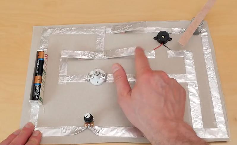
Maker Dave
Link hsmag.cc/NoWireCircuit
Project
Project
LENS 69
ACCESSIBILITY SWITCH
he anonymous genius behind this hack works with assistive technology, and wanted to create a switch that can be easily operated by someone with weak muscle tone. Originally created for a little boy with spinal muscular atrophy, they’ve since used the switch with many clients. The switch involves creating a 5” pad using cardboard and foam, and wrapping it with aluminium foil. The next step involves creating a wiring harness using an audio cable and some alligator clips.
It involves stripping the wires on the cable and the clips, and soldering them properly so that you end up with an audio cable that splits into two alligator clip leads. Clip one clip to a piece of aluminium wrapped around the user’s finger, and the other one to the pad. Plug the audio end into a switch-adapted device. The switch activates when the foil-wrapped finger touches the pad. Ingenious!
Project Maker Assistive Technology Services
Project Link hsmag.cc/AccessSwitch
T DIY PENDANTS
Right In addition to the touchand-release switch, the maker has also shared ideas for other types of accessibility switches
Project Maker Gina
Project Link hsmag.cc/FoilPendant
J
ust because it’s so malleable yet sturdy, aluminium foil lends itself nicely to crafty builds. Gina’s used it to create some pendants with her boys that, in addition to necklace charms, can also be used with key chains and backpack clips. Her process is simple. Cut a circle 1.5” in diameter, from an old cereal box, and a slightly bigger one from the aluminium foil. Then draw a simple design on the cardboard, and cover the outline of the design with glue and yarn, and let it dry. Use a glue stick to coat the dull side of the foil and wrap it around the cardboard design. Finally, rub the foil with a piece of felt to help the yarn design show through. Colour the design with a permanent marker, punch a hole at the top to add a pendant clasp, and you’re done.

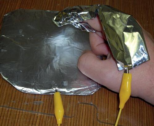
70 FEATURE
Improviser’s
Toolbox: Aluminium Foil
Right
These homemade pendants, that can be paired with yarn, ribbon, and chains, make for wonderful Mother’s Day gifts

CUSTOM COOKIE CUTTERS
T
ired of the same old cookie shapes, Allen decided to fabricate some cookie cutters of his own using aluminium foil plates. Before you begin, first draw the shapes for your cookie cutters on paper, in the size that you want them. Allen suggests you keep the angles to a minimum, which will save you time when creating the cookie cutters. Then, use a thread to measure the length of the entire design, and add 4 cms to it to
“Allen suggests you keep the angles to a minimum, which will save you time when creating the cookie cutters”
compensate for the joints. Now grab the aluminium foil plate, and cut them out as per the length of the shape. You can use any amount as width, though Allen suggests using 4” for the smaller shapes and 5” for the bigger ones. Then, fold the cut-out piece lengthwise, making three layers at the minimum for good thickness. Now, start bending the folded piece over the shape you sketched on paper earlier. This is the most time-consuming part says Allen, though you only need to concentrate on the bottom edge that’ll cut the dough. Depending on the shape, you can use some tools, such as a steel ruler, to help bend the folded piece of aluminium foil. When you’re done, use non-toxic glue to paste the ends to complete the cookie cutter.
LENS 71
Project Maker Allen T. Project Link hsmag.cc/CookieCutter
Above For best results, Allen suggests you bend the cut-out piece of aluminium foil along equally distributed fold lines
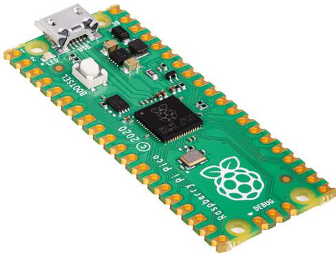

Subscription starts with next issue Raspberry Pi Pico With your first 12-month print subscription This is a limited offer. Not included with renewals. Offer subject to change or withdrawal at any time. FREE! Subscribe online: hsmag.cc/subscribe SUBSCRIBE TODAY Get 12 issues of HackSpace magazine delivered to your door for just £55 (UK) £90 (USA) £90 (Rest of World) £80 (EU) SUBSCRIPTION
FORGE
HACK MAKE BUILD CREATE
Improve your skills, learn something new, or just have fun tinkering – we hope you enjoy these hand-picked projects


Start your journey to craftsmanship with these essential skills SCHOOL OF MAKING PG 74 74 Pico’s Programmable I/O
78 PG Add encryption to your IoT setup MQTT SECURITY 80 PG LASER PRINTING Accurately cut your own stencils 88 PG CURVY PRINTS Creating twisting designs in FreeCAD 84 PG RETRO JOYSTICK Computing like it’s 1989 CROCHET A plushie for keeping your components safe 94 PG
Using Pico’s Programmable I/O with MicroPython
SCHOOL OF MAKING
Using Pico’s Programmable I/O with MicroPython
Learn PIO by blinking LEDs

Ben Everard
@ben_everard
Ben's house is slowly being taken over by 3D printers. He plans to solve this by printing an extension, once he gets enough printers.
rogrammable I/O is a unique feature of Raspberry Pi Pico that lets you handle data going out of, or into the I/O pins without needing CPU intervention. What does this mean? Let’s take a look using blinking lights as an example. There’s an LED on pin 25 of Pico, so we can get started using this with no extra hardware.
Sometimes a blinking LED is needed to let the user know what’s going on with your project. That’s easy enough to do, but it’s not always visually appealing. A slow fade-in can be a better look. While this isn’t hard to program on its own, if you’ve got other processing to do, it can be hard to juggle CPU time to make sure the fade remains smooth. Let’s take a look at how to do this with Programmable I/O in MicroPython.
Programmable I/O (PIO for short) is based around state machines. These are mini-processors that you can program with a special form of assembly language. For our purposes, we’re just going to be using one instruction, set. In this case, it’ll be used to set a pin as high or low.
GETTING MICROPYTHON
Before running this, you’ll need to be set up with MicroPython. There are two parts to this: first you need to install the MicroPython firmware on your Pico, then you need an editor to write the code and upload it (we recommend Thonny).
You can grab the latest version of the firmware from rptl.io/rp2040-get-started, and you can get Thonny from thonny.org
There’s a full guide to getting started in the official book, Getting started with MicroPython on Raspberry Pi Pico. You can buy this in print or download it for free at hsmag.cc/picobook
Each Pico has eight state machines, and we’re going to use two of them. One will continuously turn the LED on, while the other will continuously turn it off. We get our fade by running these at slightly different frequencies so they interact with each other in a cycle that creates a fading effect.
from rp2 import PIO, StateMachine, asm_pio from machine import Pin import time
@asm_pio(set_init=PIO.OUT_LOW)
def led_off(): set(pins, 0)
@asm_pio(set_init=PIO.OUT_LOW)
def led_on(): set(pins, 1) s
m1 = StateMachine(1, led_off, freq=20000, set_ base=Pin(25))
sm2 = StateMachine(2, led_on, freq=20002, set_ base=Pin(25))
sm1.active(1) sm2.active(1)
As you can see, we use the @asm_pio decorator to let MicroPython know that a method is written in PIO assembly. We need to pass a parameter to the PIO assembler to let it know the initial state of the pin. We’ve set it low in both programs. In this setup, each state machine does one thing: turns an LED on (with a 1) or off (with a 0). These programs automatically loop, so they’ll continue turning the LED on and off.
74
P
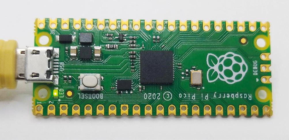
We need to load the programs into state machines before we can use them. The StateMachine class takes a range of parameters, but we only need the most basic ones:
• The state machine number
• The program we want it to run
• The frequency we want to run it at
• The pin we want the set instruction to operate on
As you can see, we’ve set them running at slightly different frequencies, so the programs get a little out of sync over time. This means that the proportion of time the LED will be on or off will vary, leading to a rhythmical fading in and then turning off.
Finally, we need to activate the state machines. This will set them running in the background and leave the main MicroPython program to get on doing whatever you want to do. If you want to disable them, you just need to run:
sm2.active(0)
…to stop the state machine turning the LED on.
MORE CONTROL
In the previous example, we looked at a way of fading an LED in and out without any CPU involvement, but if we want more control, we need to engage the CPU and use PWM. PWM stands for ‘pulse-width modulation’ and is a way of setting the brightness of an LED (among other things) by flicking it on or off very quickly. The larger the proportion of the time it’s on, the brighter it is.
Raspberry Pi Pico does have a PWM peripheral (see here for an example of how to use it: hsmag.cc/PWMPeripheral), but we’re going to implement our own PWM to help us get used to working with PIO. The full code for this example can be found at hsmag.cc/PWMCode if you want to just download it.
First we need to import some things, create a program, and load it into a state machine.
from machine import Pin from rp2 import PIO, StateMachine, asm_pio from time import sleep
max_count = 500
@asm_pio(sideset_init=PIO.OUT_LOW) def pwm_prog():
pull(noblock) .side(0) mov(x, osr) mov(y, isr) label("pwmloop") jmp(x_not_y, "skip") nop() .side(1) label("skip") jmp(y_dec, "pwmloop")
pwm_sm = StateMachine(0, pwm_prog, freq=10000000, sideset_base=Pin(25))
We are doing things a little differently here in a few ways. Firstly, we aren’t turning pins on and off using set , we’re using .side() . This is known as
Above All embedded programmers start with flashing lights
75 FORGE
Using Pico’s Programmable I/O with MicroPython
SCHOOL OF MAKING
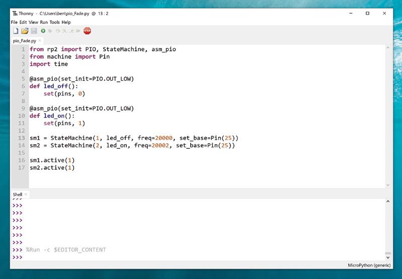
We can place markers at certain points in our code that allows us to 'jump' to them
side setting and it runs concurrently with other instructions. Note that we define the pin with sideset_base rather than set_base . This means that you can use set and sideset on different pins. There’s also the out option, so you can use three independent groups of pins from an individual PIO program.
Let’s go through this line by line, as there are a few unfamiliar bits here.
• pull(noblock) .side(0): The pull command takes data from the output FIFO and places it in the Output Shift Register. The noblock option means that if there is no data in the output FIFO, then it will continue running. If noblock is omitted, it will pause here and wait for data. .side(0) will turn the sideset pin (25 in this case) off. FIFOs or First In First Outs are data structures that do exactly this. The first bit of data you put in will be the first bit out the other end. They’re sometimes known as queues and they perform a similar function of queueing up data before an input is ready to accept it.
• mov(x, osr): Move data from the Output Shift Register in the x (one of two scratch registers we can use – the other being y. You can think of these a little like variables).
• mov(y, isr): Move data from the Input Shift Register into y. Usually, the ISR is used to store data read in from input pins, but in this case, it’s being used a bit like a temporary variable. We’ll see later how we load data into the ISR.
• label('pwmloop'): We can place markers at certain points in our code that allow us to ‘jump’ to them.
• jmp(x_not_y, 'skip'): This performs a test between x and y. If they are different, then the program jumps to the label ‘skip’ and doesn’t execute any of the code in between.
• nop() .side(1): The program will only reach this line if x is equal to y (if they are not, then the jump in the previous line will happen). nop means nothing happens in the main instruction, but the side(1) will turn the sideset pin on.
76
” ”
Right
Two state machines fight it out to control an LED
• jmp(y_dec, 'pwmloop'): This jumps to the label pwmloop . As this is above this line, it will create a loop (as the label suggests). Each time it jumps, it will decrease the value of y by one, and if it gets to 0, it will not do the jump. As such, this performs a little like a for loop in Python with numbers counting down.
• If the program gets to the end, it automatically loops back to the start.
A key to the way this program works is that we preload the ISR with the number of loops we want our PWM cycle to take. In our example, we’ve used 500, but it can be any 32-bit number.
The pull line will see if there is a new value to use, but if there isn’t it will continue using the current value of the OSR (setting the PWM pin to 0 in the process) and load this into the x register. The program then loads the number of loops from the ISR into the y register. The PWM loop (between the label and the final jump) will continue to run until y reaches 0. When y reaches the value of x, it will turn on the sideset pin.
Let’s take a look at how to preload the ISR with data:
pwm_sm.put(max_count)
pwm_sm.exec("pull()")
WS2812B NEOPIXELS
If you want more colours in your LEDs, you can use WS2812B LEDs, also known as NeoPixels. These are chainable RGB LEDs, so you can connect lots of them to a single pin on your Pico, and have them display a huge range of colours.
There’s a library that uses PIO to control these at hsmag.cc/PicoWS2812B

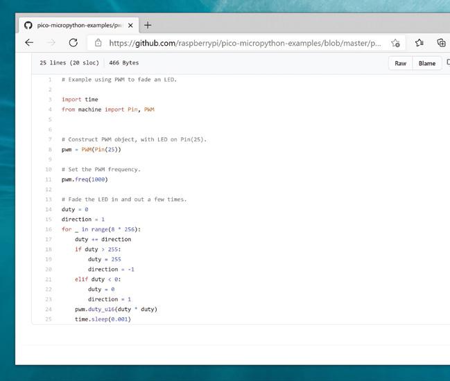
pwm_sm.exec("mov(isr, osr)") pwm_sm.active(1)
First, we use the put method to put data in the state machine’s output FIFO. Then we use the exec method (which can run arbitrary commands in the state machine) to load the value into the ISR. Finally, we activate the state machine so that it’s ready to start accepting values.
To set the brightness of the LED, then, we just have to feed a value between 0 (completely off) and 500 (almost fully on) into the output FIFO.
while True: for i in range(500): pwm_sm.put(i) sleep(0.001)
Again, we use the put method to feed data into the output FIFO of the state machine.
That is it for this part: we can now use PIO to set the brightness of an LED by flashing it on and off really fast.
This is the basics of PIO on Raspberry Pi Pico. The great thing about it is that it gives you the ability to do cycle-accurate I/O even in MicroPython, so you can use it to control things that need accurate timing (like PWMed LEDs). It’s a fairly simple language with just nine instructions, but at the same time, it’s hugely powerful, letting you connect to a wide variety of hardware.
77 FORGE
Above
For details on how to use the real PWM peripheral on Pico, see hsmag.cc/ PicoExamples
Add security to your MQTT connections

Rob Miles
@robmiles
Rob Miles has been playing with hardware and software since almost before there was hardware and software. You can find out more about his so-called life at robmiles.com
QTT is a great way to connect devices together. But it can be insecure. We’re going to examine security on MQTT, and find out what you can do to protect your applications. Your author has made some resources, which you can find by following this link: hsmag.cc/MQTTSec
WHAT IS MQTT?
MQTT (Message Queuing Telemetry Transport) was developed by IBM as a system management tool. It uses a ‘publish and subscribe’ mechanism which allows connected devices to communicate. The MQTT broker maintains a list of ’topics’. A device connected to the broker can subscribe to topics and publish messages to a topic. For example, a broker could manage a topic called ‘greenhouseTemp’. A temperature sensor would publish readings to this topic and a heater controller would subscribe so that it gets a reading when the temperature in the greenhouse changes. Many devices can subscribe to a single topic and the broker will send out messages to all of them as required.
Messages are just lumps of data as far as MQTT is concerned. A temperature reading could be a
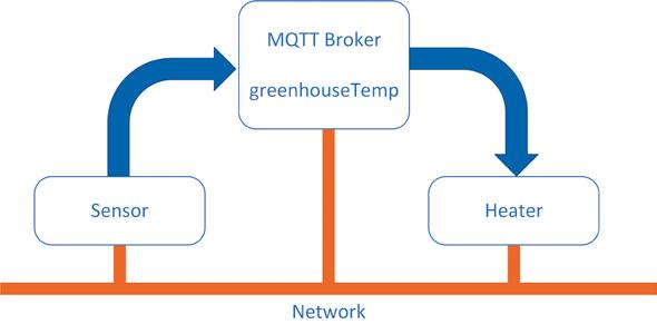
simple numeric value, or a tiny chunk of text encoded using JSON.
You can create completely open MQTT brokers that allow any device to connect. You might think this is OK. After all, who really cares about the temperature in the greenhouse? However, you must remember that someone could connect a device that publishes invalid temperature values and perhaps damage the heating system.
If your MQTT broker is connected to a totally private network (for example, a local WiFi network hosted by a Raspberry Pi), you might be able to get away with no security, but it would be extremely dangerous to connect such an open network to the internet.
PASSWORD PLEASE
You can add security by requiring devices to give a username and password when they connect. This is more complex to configure and manage because you need to set up the password and then configure your devices to use it. All the devices connected to
SECURITY AND RISK
Security is always a trade-off between risk and effort. The more effort you put into managing security, the less risk you are exposed to. For any installation, you need to look at the risks you are running and decide which ones you can live with. Your author is happy to live with a lower level of security (just a passwordprotected connection) for data devices on his private networks, but always uses secure sockets if sending data to a server on the
If you want even higher levels of security, you can give each device a unique client certificate. This gives you the ability to control access at an individual device level, and allows authentication to expire after a particular time. This is much more secure, but now you must create and distribute keys into the devices. Search for 'MQTT and X509' to find out more about this.
TUTORIAL 78 Add security to your MQTT connections
Keep your IoT applications safe from prying eyes and remote takeover
M
internet.
Figure 1
Sensor Heater Network MQTT Broker greenhouseTemp
An MQTT broker passing messages
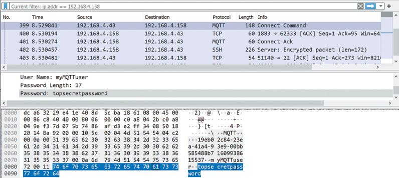
the broker use the same username and password and, if you change the password on the broker, you will have to update all the devices. However, at least you will have the satisfaction of knowing you have made it just that bit harder for someone to hijack your greenhouse heating system.
PROTECTING FROM PRYING EYES
To get more security, we can encrypt our messages using secure sockets. Whenever you visit a website with an address that starts ‘https’, you are using ‘secure socket’ technology that solves two security problems. It encrypts data so that anyone eavesdropping on the session sees incomprehensible gibberish. It also makes sure that your browser is connected to the authentic server. This prevents naughty people setting up fake versions of services. We can use secure sockets to make our MQTT connections safe from prying eyes and unwanted interference.
KEY INFORMATION
Secure sockets are implemented using lumps of data (keys) held at each end of a conversation. A full description of public-private asymmetric key
HOME SWEET
HOME NETWORKING
You can think of your home network as your own private internet. The router that provides your connection to the internet manages a local network for all the devices in your house and connects them to the internet as required. The router acts as a filter, which means that a hacker in a distant foreign land (or even the house next door) would not be able to use Wireshark to grab MQTT passwords from devices on your home network. However, this does mean that you should be careful when a stranger asks you for your WiFi password so that they can check their email…
Figure 2
Wireshark is a network monitoring application that you can use to watch traffic in a network. It's a free download from wireshark.org. It is a useful tool for debugging your network. Wireshark can capture MQTT credentials from unencrypted brokers, as shown here
encryption is slightly beyond the scope of this article, but suffice it to say that it starts with two keys that ‘fit together’. If I have one key, I can use it to decrypt messages that you’ve encrypted with the other one. This means that I can tell that it is you talking (since my decryption only works if the data was encrypted with your key).
If the key pairs are signed by trusted ‘Certification Authorities’ they will also prove identity, since I trust the authority that made your keys. We can also act as our own security authority and create and use ‘self-signed’ key pairs. These are good for keeping messages secret, but don’t prove identity.
SECURE SOCKETS AND MQTT
To make an MQTT connection secure, you add some key files to your Mosquitto installation and then use the following code in your devices to employ secure sockets.
mqtt = new MQTT(); while (!mqtt->connect( "Demo", // device name "your mqtt host", // mqtt host "your mqtt username", // username "your mqtt password", // password "DemoIn", // topic subscribed to "DemoOut", // topic published to true, // true for secure 10 // timeout in secs )) { Serial.println("."); }
This code uses the author’s library to make a connection to an MQTT server which is protected by a password. Just fill in the MQTT host name and your username and password and it does the rest. You can select secure or insecure operation.
Full details can be found in the author’s GitHub pages (hsmag.cc/MQTTSec).
QUICK TIP
Secure sockets need more RAM to manage connections. We've had problems with our ESP8266 applications running out of stack space when we use them with secure sockets. If you want your device to work with large amounts of data (perhaps it has a lot of NeoPixel lights attached), you should use an ESP32 in it.
YOU’LL NEED
A Mosquitto MQTT server running on a Raspberry Pi, Windows PC, or other platform. You can download Mosquitto from mosquitto.org
ESP32 and ESP8266 powered remote devices
79 FORGE
Screen printing with lasers
Prepare screen printing frames with a laser cutter and print your own posters and clothes

Screen printing is a favourite for custom clothing and art prints, because the printing process can be fast, repeatable, and easy to automate. A screen print is essentially a very advanced stencil that uses fabric mesh to hold ink-resistant masks in place. Creating a printing screen usually involves applying a special photosensitive emulsion to fabric mesh stretched over a frame, and then developing the screen with a design in a similar way to making a photographic paper print.
It’s not a difficult process, but it does require special equipment. You can also make simple screens by applying pre-cut vinyl directly to the mesh, but the vinyl can’t be cut into very intricate patterns. In this article, you’ll see how you can use your laser cutter to shortcut the process, and get printing with the minimum of fuss.
If you’re going to get into screen printing, then you’re going to need a screen. Making a screen is easy and, if you’ve ever stretched a canvas, you’ll be familiar with the technique. Begin by cutting some
YOU’LL NEED
Wood for frame approx. 2 cm × 1 cm × 100 cm
Steel woven wire mesh filter screen between 60 and 200 mesh
Fibre
Screen printing ink

TUTORIAL 80
Screen printing with lasers
Right
Some fabric inks will set with the addition of a catalyst, while others require heat to get them to become colourfast. If you don’t set the ink properly, it will wash out of the garment. It’s also worth pre-washing the garment before you print to prevent colour bleeding from the fabric into the ink
pencil
Acrylic spray paint
Dr Andrew Lewis
Dr Andrew Lewis is a specialist fabricator and maker, and is the owner of the Andrew Lewis Workshop.
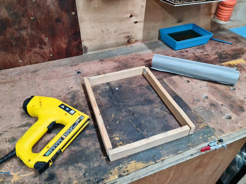
wood to make a square about the size of an A4+ sheet of paper (250 mm × 337 mm). You don’t have to make a fantastic job of the jointing, as long as the pieces hold together and are flat, with the sides at right angles. Staples, glue, and brad nails should be fine for holding the frame together.
On a normal screen printing frame, the mesh will be made of nylon, silk, or some other fabric. To work with the laser, you’ll need something more resilient than textiles. Take a piece of stainless steel mesh large enough to stretch around the frame, and staple it to one side, pulling the mesh tight as you go. The tension of the mesh on the frame is important to get good prints, so keep the mesh as tight as you can. Work your way around the frame, stapling the mesh in place and drawing the tension. Once you’ve fixed the mesh
PICK YOUR INK
There’s a huge variety of screen printing inks available, and you’ll have to experiment to some extent if you want to get the best results from your screen. If the ink is too thick, you’ll probably find that you can’t push it across the screen properly. If the ink is too thin, it will go through the screen and seep underneath the edge of the mask, ruining your prints. If you’re using a waterbased ink, you can thicken it by leaving it with the lid off to evaporate some of the water. You could also add a thickening agent if you need to.
in place, go around with some extra staples to make doubly sure. You can use some masking tape to tidy up the edges of the frame and protect your fingers from any sharp strands of mesh.
You don’t need photosensitive emulsion for the lasering process: you’ll be using acrylic spray paint. Apply a few thick coats of acrylic spray to both sides of the mesh. The paint needs to totally seal the mesh. You can check this by holding the screen up to a bright light and making sure you don’t see any pinpricks of
When you’re making the frame, the important side is the one that will have the mesh stretched over it. Keep that edge as square and flat as possible. A combination of glued butt joints and staples should be enough to hold the frame in shape
Below
If you have access to some canvas pliers, stretching the mesh on the frame should be considerably easier. Canvas or upholstery pliers have a wide jaw and a raised section on the back to increase leverage when pulling canvas tight
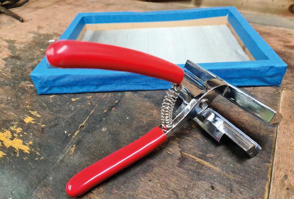
81 FORGE
Left
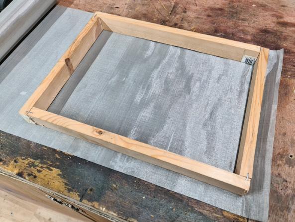
Above Stainless steel filter mesh is relatively inexpensive and rugged enough to stand up to bombardment from lasers and squeegees. Staple the mesh onto the frame as though you’re stretching a canvas
Right
A bright light is very useful for checking your mesh is etched properly. You can see a flaw at the foot of this etching, where excess heat from the laser has damaged the mesh. This screen won’t survive many prints before the mesh around the foot disintegrates completely. It’s best to start again and etch a new frame with a lower power and more passes if this happens
light shining through the acrylic. Two or three coats of paint should be enough to seal the screen completely. Once the mesh has dried for a couple of hours, you can load the frame into the laser cutter and etch your design into it. It’s best to position the frame with the mesh side closest to the laser, leaving a void below. Detail is critical, so don’t forget to adjust the height of the frame to match the focal point of the laser. It might be tempting to etch the design in a single pass, but
applying too much concentrated power on small details can generate enough heat to damage the steel mesh. Make four or five laser passes with a lower power (10–15 percent of full power at 200 mm/s, depending on the laser) to get the best result. It should be obvious when the mesh is completely etched, as you’ll be able to see through the etched sections. Hold the screen up to a bright light to double-check you’ve got a good,
” ”
Proper screen printing jigs hold the frame slightly above the surface that you want to print on
even etch. Give the screen a quick wipe with some water and a soft sponge to get rid of any residues from the etching process, and let it dry.
You’re ready to screen-print, so grab some ink, a squeegee, and something to print on. Proper screen printing jigs hold the frame slightly above the surface that you want to print on. That’s one of the reasons that tensioning your frame is important. You need to be able to push the screen down onto the surface and
QUICK TIP
Some printing inks contain latex and other harmful chemicals. Be careful and check the MSDS data, especially if you have an allergy.

TUTORIAL 82
Screen printing with lasers


have it spring back up again behind the squeegee as it moves along. You don’t have a fancy frame, but you do have the next best thing, which is a few 2 p coins. You can stack or tape coins to the corners of your frame to keep it slightly raised from the print surface. It might look a bit odd, but it will work.
Take your frame and place it on the object you want to print. Put some ink at one end of your screen, and use your squeegee to pull the ink across the frame without pushing down. This is called flooding or a flood pass, and the idea is to spread the ink across the screen, to improve print quality and to prevent waterbased inks from drying in the mesh of the screen and blocking it between prints.
Now, draw the squeegee across the screen again, this time pushing down gently onto the print surface as you pull the squeegee along. If you feel more comfortable, you can push the squeegee rather than pull it. Remove the frame, let the design dry, and
repeat as necessary. You’ll probably need to make a few practice runs before you figure out all of the variables. The thickness of the ink, the amount of pressure you apply, distance between the frame and the print surface, the fineness of the screen mesh, the material you’re printing to, and even the temperature of the room make a difference to the final result.
If you’re really struggling with the squeegee and find that you can’t get a good image, then chances are that the problem is with your ink or with the screen itself. If the screen is blocked by dried ink, or hasn’t been fully etched, you won’t be able to get a good result. If the viscosity of the ink is wrong, you’ll have trouble controlling the flow of ink onto the print surface. If you’ve been fiddling around for a long time and your frustration levels are rising, try using the screen as a simple stencil, and test it by dabbing ordinary acrylic paint through the screen with a sponge or stiff brush. If you still don’t get an image from that, then try using a frame with a coarser mesh, or thinning the ink.
NO WASTE
You can reuse your frames by cleaning the acrylic off with acetone or another solvent and then respraying the mesh again, ready to etch on the laser. If you accidentally leave some ink to dry on the frame, you should be able to clean it with water and a white or green abrasive pad. The acrylic paint is more resilient than you might expect, and will withstand a fair amount of abuse before it gets damaged.
QUICK TIP
The finer the mesh you use, the more detail you can reproduce – but too fine a mesh will make it very hard to force the ink through the screen.
Above You will have to practise and experiment to get the best results from screen printing. After a while, you’ll get a feel for what needs to be changed to get the results you’re looking for. Starting out with a simple frame is a good way to get a feel for the process, in just the same way that starting with a film camera is a good way to learn photography
Left
If you already have access to a laser cutter, then making a laser screen is a great way to get started in screen printing without spending money on lightsensitive goo. Just remember to reverse the image when you etch the frame, as you’ll be etching it from the front of the mesh, not the back
83 FORGE
Use a retro DB9 joystick with Raspberry Pi 400

K.G. Orphanides
K.G. makes, writes about, and helps to preserve unusual gaming software and hardware. @KGOrphanides
Get the classic ZX Spectrum experience with Raspberry Pi 400 and a GPIO joystick
Raspberry Pi 400 is, with its integrated keyboard and tweaked performance, a modern home micro. This month, we pay tribute to one of the computers that helped inspire its look by emulating Sinclair’s ZX Spectrum, complete with the latest games and retro joysticks connected via GPIO. These use the D-sub connector popularly called DB9, also known as DE-9.
01 Install the Free Unix Spectrum Emulator
Also available in the RetroPie emulation distro we’ve used in previous tutorials, the FUSE ZX Spectrum emulator can be found in Raspberry Pi OS’s standard repositories, so installation is a bare minimum of fuss. Open a Terminal window and type:
fuse-sdl
Press F2 to open FUSE’s file browser, navigate to AbbayeDesMorts.tzx.zip , and press ENTER The game should load and run automatically. For full-screen mode, press F1 , go to Options, and select ‘Full screen’. Take note of the Filter option in the same menu, which lets you choose the emulator’s upscaling method: ‘TV 3x’ gives you some pleasing scan lines and the correct aspect ratio.
Wiring up the DP9 port to Raspberry Pi’s GPIO is a fairly simple process
Warning!
Copyright
Many (but not all) Spectrum games can be legally downloaded. See our Legal ROMS page for more information. magpi.cc/legalroms
You’ll Need
> DB9 joystick
> DB9 breakout board magpi.cc/ db9breakout
> 10–20 male-tofemale jumper cables magpi.cc/ mfjumpers
> DB9 GPIO driver source magpi.cc/ db9gpiogit
sudo apt install fuse-emulator* spectrumroms opense-basic libspectrum8
This will install FUSE, its GTK and SDL front ends, and both open-source system ROMs and the original Spectrum system ROMs. Permission has been granted for free modification and distribution of the latter (magpi.cc/SpecROMs).
While the open-source ROM can only handle a limited selection of files, that spectrum-roms package will allow you to play a wide array of games, including the latest generation of technically spectacular releases for the platform.
02 Test FUSE
Next, we’ll make sure FUSE is working with the ZX Spectrum port of Locomalito’s open-source classic, L’Abbaye Des Morts. In a Terminal, type:
wget https://spectrumcomputing.co.uk/zxdb/ sinclair/entries/0030109/AbbayeDesMorts.tzx.zip
03 Wire up your joystick port
Standard DB9 connectors split the nine pins of your cable into nine screw-down terminals. We found it most convenient to use male-to-female jumper cables for this, clamping the male tips into our DB9 breakout connector.
For a classic single-button joystick like the Competition Pro Retro we used, pin 1 is up, pin 2 is down, pin 3 is left, pin 4 is right, and pin 6 is fire. Pin 8 connects to ground – we recommend using a green cable for it. Some joysticks may require you to connect port 7 to a 3.3 V power connector on the GPIO, but the Competition Pro does not.
See the ‘DB9 pins’ box (overleaf) for an at-aglance DB9 connection table.
04 Wire up Raspberry Pi
Wiring up the DB9 port to Raspberry Pi’s GPIO is a fairly simple process, although you’ll have to do some careful pin counting. On Raspberry Pi 400, pin 1 is at the top right of the horizontally
MAKER
TUTORIAL 84 Use a retro DB9 joystick
Raspberry Pi
with
400
DB9 breakout boards are silk-screened with pin numbers, making it easy to connect your jumper leads

oriented GPIO port and pin 40 is at the bottom left. Remember that GPIO numbers don’t correspond with pin position numbers.
For a reminder of where everything is, open a Terminal and type: pinout
Our diagram (Figure 1, overleaf) shows where the female jumpers connected to your DB9 port need to go on Raspberry Pi. For a single one-button joystick, up goes to GPIO 4, down to GPIO 7, left to GPIO 8, right to GPIO 9, and fire to GPIO 10.
05 Build the DB9 joystick driver
Let’s build the driver. Enter this in a Terminal window:
sudo apt install dkms raspberrypi-kernelheaders
git clone https://github.com/marqs85/db9_ gpio_rpi.git
cd db9_gpio_rpi
sudo cp -r db9_gpio_rpi-1.2 /usr/src/db9_ gpio_rpi-1.2/
sudo dkms add db9_gpio_rpi/1.2
sudo dkms build db9_gpio_rpi/1.2
sudo dkms mkdeb db9_gpio_rpi/1.2 --sourceonly
sudo modprobe --first-time db9_gpio_rpi map=1,1
pullup.sh
> Language: Bash
001. 002. 003. 004. 005. 006. 007. 008. 009. 010. 011. 012. 013. 014. 015. 016. 017. 018. 019. 020. 021. 022. 023. 024. 025.
#!/bin/bash
Any classic or modern reproduction 9-pin (DB9) joystick will work for this – you can even use a Sega Mega Drive pad in a pinch
DOWNLOAD
magpi.cc/pullupfix
# fix for db9_gpio_rpi driver issue https://github.com/marqs85/ db9_gpio_rpi/issues/8
# RPi 4 and 400 need this tweak to speak to db9_gpio_rpi gpio connected controllers as some inputs need explicit pullup
# ensure that you’re applying the pullups to the correct pinsthis is for a standard deployment of the driver
#
# Use:
# chmod pullup.sh +x
# add /path/to/pullup.sh to /etc/rc.local to load on boot
# Joyport /dev/input/js0
raspi-gpio set 4 ip pu raspi-gpio set 7 ip pu raspi-gpio set 8 ip pu raspi-gpio set 9 ip pu raspi-gpio set 10 ip pu raspi-gpio set 11 ip pu raspi-gpio set 14 ip pu
# Joyport /dev/input/js1 - if we connect a second joystick raspi-gpio set 15 ip pu raspi-gpio set 17 ip pu raspi-gpio set 18 ip pu raspi-gpio set 22 ip pu raspi-gpio set 23 ip pu raspi-gpio set 24 ip pu raspi-gpio set 25 ip pu
THE FULL CODE: 85
TUTORIAL
DB9 pins
For a one-button joystick – including multi-button sticks with only single-button functionality – connect these pins on your DB9 breakout board.
THE MAGPI

This tutorial is from in The MagPi, the official Raspberry Pi magazine. Each issue includes a huge variety of projects, tutorials, tips and tricks to help you get the most out of your Raspberry Pi. Find out more at magpi.cc
That map option defines what kind of joystick you’re using, with each number classifying a different type of joystick As we’re using a one-button joystick, map=1,0 would do it, but 1,1 means we can connect a second stick of the same type to a second port.
Although many Spectrum games support joysticks, you’ll often have to enable support for these
06 Test your joystick
Top Tip
GPIO reference
If you’re flummoxed by GPIO pin numbering, see the official docs at magpi.cc/gpio
Building and loading the driver won’t quite get us to a functional joystick, as the driver isn’t fully compatible with Raspberry Pi OS’s recent use of raspi-gpio instead of gpio. However, this is a great time to test your joystick to make sure that it’s wired up correctly.
sudo apt install jstest-gtk jstest-gtk
You should see your joystick in the peripherals list. When you click into it, if you’re using a Competition Pro Retro or similar joystick, you’re likely to find that the fire button is jammed on and that the horizontal x axis is stuck at the left.
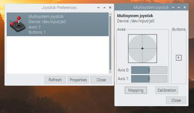
07 Pull-ups are good for you
This is because your GPIO needs to be set up to handle the joystick’s pull-up switches. On a standard DB9 GPIO configuration, the script you’ll find at magpi.cc/pullupfix will do this for you. Create it using your preferred text editor and save it somewhere handy. We’ve put ours in /home/pi/pullup.sh. Test it by running:
sh /home/pi/pullup.sh jstest-gtk
If the joystick is now aligned properly and the button isn’t stuck on, you’re in business.
chmod +x /home/pi/pullup.sh
Finally, let’s load those pull-up settings on boot.
sudo mousepad /etc/rc.local
Above the exit line, enter the following: /home/pi/pullup.sh
You can also place the pull-up code directly in rc.local if you wish.
08 Load on boot
Once you’re satisfied that your joysticks work, you’ll want to load the driver module on boot.
mousepad /etc/modules …and add:
After saving and exiting the file, enter: sudo mousepad /etc/modprobe.d/db9.conf
This file should contain the following line:
sudo
db9_gpio_rpi
The jstest-gui program allows you to test your joystick and also indicates whether it’s working as it’s supposed to
DB9 pin Joystick function 1 UP 2 DOWN 3 LEFT 4 RIGHT 56 FIRE 78 GROUND 9 -
86 Use a retro DB9 joystick with Raspberry Pi 400
options db9_gpio_rpi map=1,1
If you’re using a different joystick and configuration, you’ll need an appropriate map, and possibly some extra GPIO connections, which you can find at magpi.cc/db9gpio
Reboot Raspberry Pi and use jstest-gtk to ensure that everything is working as it should. You can now use the driver as a generic controller input device.
09 FUSED joysticks
FUSE doesn’t enable joystick support by default, so we’ll have to set that up. Run fuse-sdk, then press F1 for the menu. Go to Options > Peripherals > General. Press SPACE to enable Kempston joystick support, then press ENTER Press F1, then Navigate to Options > Peripherals > Joysticks and make sure both Joystick 1 and Joystick 2 are set to Kempston. If not, press ENTER, press ENTER again to open the Joystick type options, navigate to Kempston on the list, and press ENTER again.
Note that some games may default to using Joystick 2, so you’ll want to configure both, even if you only have a single stick connected.
When you’re happy with your settings, open the Options menu and select Save.
10 Game configuration
Although many Spectrum games support joysticks, you’ll often have to enable support for these. L’Abbaye des Morts enables joystick support by default, but its menus provide a good example of what to look for.
Load the game and then press C on the keyboard to access the control configuration. Pressing 1 here enables and disables Kempston joystick support. In other titles, you may need to explicitly choose to use your joystick to control the game if you want it to work.
11 Get game
The Spectrum’s been a long-time homebrew favourite, with software continuing to come out for years past its original availability. There’s been a resurgence in popularity of the platform with the release of a number of successors, most recently the ZX Spectrum Next.
As ever, the indie-friendly itch.io digital distribution platform is one of the best places

to find both free and commercial releases for the Spectrum, and we’ve put together a list at magpi.cc/zxspectrumgames
12 Boot to black
Finally, let’s start FUSE on boot for that authentic Spectrum ambience. In /home/pi/.config/autostart create a text file called fuse.desktop. If the directory doesn’t exist, create it. Add the following lines to your new file:
[Desktop Entry]
Type=Application
Name=FUSE
Exec=/usr/bin/fuse-sdl --full-screen
You can exit FUSE at any point to return to Raspberry Pi OS’s familiar desktop.
GPIO connections
Figure 1 GPIO connection points for two singlebutton joysticks, corresponding to the ‘GPIO connections’ table (below). Joystick 1 is purple, joystick 2 is orange. Use your choice of ground pins for each controller: ground pins 6 and 14 are marked in green here
Top Tip
Get in touch
Is retro gaming your hobby? Drop KG a message on Twitter @KGOrphanides if you have any early-2000s physical Linux game releases.
GPIO connection table for two one-button joysticks. The db9_gpio_rpi driver uses these pins by default for single-button joysticks. You will also need a ground connection for each.
BUTTON Joystick 1 GPIO PIN Joystick 2 GPIO PIN UP GPIO 4 GPIO 15 DOWN GPIO 7 GPIO 17 LEFT GPIO 8 GPIO 18 RIGHT GPIO 9 GPIO 22 FIRE GPIO 10 GPIO 23
87 FORGE
Figure 1
FreeCAD: let’s get curvy!
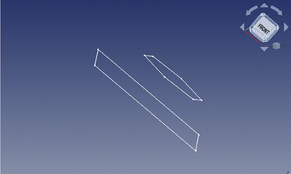

Jo Hinchliffe
@concreted0g
Jo Hinchliffe is a constant tinkerer and is passionate about all things DIY. He loves designing and scratch-building both model and high-power rockets, and releases the designs and components as open-source. He also has a shed full of lathes and milling machines and CNC kit!
Next, select the original rectangle sketch in the file tree view, and then click the yellow and red 'loft a Add bendy transitions to your parts for a more elegant look
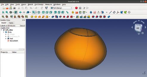
First up is the Additive Loft function, which is a method that creates straight or curved transitions between sketches – it’s a great way of creating complex flowing shapes. To start with, we will make a nonsense object just to see how it works, and then we will create a small ornamental bowl that can be 3D-printed.
On the part design workbench, create a new body and then create a new sketch on the XY plane – this should move you onto the sketcher workbench. Select the rectangle tool and draw a rectangle in this sketch. As this is a test, we don’t need to add constraints, so close this sketch now. In the part design workbench again, within the same body, create a second sketch. Click the 'New sketch' button, and select the XY plane for our second sketch.
In this second sketch, use the regular polygon tool to draw a hexagon that is smaller than the rectangle you drew – draw it inside the rectangle, and don’t worry if it overlaps a little.
Again, we don’t need to constrain the hexagon, so close the sketch. The next step is to move the hexagon sketch away from the rectangle sketch in the Z-axis. As both of the sketches are part of the same body, we can’t move the basic position of the hexagon sketch, but we can move the relative attachment point of the sketch. With the sketch containing the hexagon selected, you should see the dialogue box for the sketch in the combo view panel. In this dialogue box, there are three sections of values separated under the headings 'Attachment', 'Base', and 'Sketch'. Making sure you are in the Attachment section, click the Attachment menu, and then click to expand the Position menu. In this drop-down menu, adjust the Z-axis to raise the hexagon sketch over the rectangle –this can be any amount, but we went for 20 mm. If you are in an isometric view in the part design workbench, you should see the hexagon sketch rise above the rectangle sketch (Figure 1).
TUTORIAL 88 FreeCAD: let’s get curvy!
Figure 1
Two sketches in the XY plane with one sketch raised above the other on the Z-axis
Figure 2
Using the lofting tool can create pleasing curved results
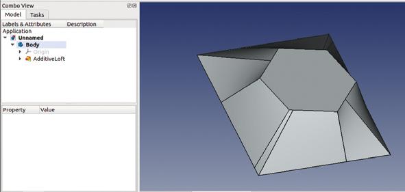
selected profile through other profile sections' tool. In the combo view panel, you should now see a window – click the 'Add section' button. Having clicked that, select the hexagon sketch in the preview window. As you do this, you should see a preview of the lofted part connected between the rectangle and the hexagon. There are a couple of checkboxes you can click: one is called 'closed' which will close the ends of the lofted object, and the other is 'ruled surface'. Clicking 'ruled surface' toggles the lofted object between having either straight line/plane geometries or curved. It is not that obvious a difference with our simple example, but we will use this in our next lofting project.
To finish, click the 'closed' checkbox and then OK to perform the loft. In the preview window, you will now see the resulting object. Lofted objects are like any other in that you can use other tools on the objects created with them, such as selecting edges for fillets. However, when the surfaces generated become complex and curved, you might find that some tools don't work and we need a different approach.
One thing people often try with the lofting tool is to apply a thickness to the resulting object to hollow it out. Sadly the thickness tools only work on simple geometries, so it’s not possible to work this way. However, let’s make a more interesting lofted object –the bowl pictured in Figure 2 – and show how we can create curved objects with defined thickness walls.
In a new project, create a body and create a sketch in the XY plane. Draw two circles constrained around the origin point and make one slightly smaller than the other; the distance between them will create the wall thickness of our object. We made our sketch with the outer circle having a diameter of 25 mm and the inner circle having a diameter of 22 mm, to give a wall thickness of 1.5 mm (Figure 4).
Close the sketch and then create another sketch in the XY plane. Create a larger pair of circles, but with the same wall thickness – we went for 45 mm and 42 mm. Close this sketch and then create a third sketch with a pair of circles constrained to match the first set we drew. With the second sketch highlighted, move these circles up the Z-axis using the same method we used


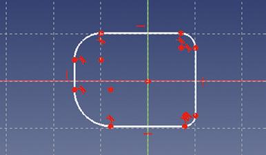
earlier with our hexagon. Move it up by 25 mm. Next, do the same with the third sketch, moving it up the Z-axis 60 mm (Figure 5). Create the loft in a similar way to the earlier example, starting by selecting the first sketch and then adding the second sketch and the third sketch in that order. If you uncheck the ruled option and the closed option, you should end up with a nice curvy shape, as shown in Figure 2
Adding one final sketch of a circle matching the outer diameter of the lowest sketch in our bowl means that we can pad/extrude to add a base to our ornamental bowl. Sweeping along a path is a similar idea to revolving a sketch and also shares some attributes of lofting. However, sweeping uses a user-drawn path or geometry that the extrusion is swept along, rather than an automatically generated one. There are a couple of approaches to sweeping in FreeCAD: one using the part workbench, the other using the part design workbench. Let's look at both to have both methods in our skill set.
Figure 3
Our completed loft experiment
Figure 4
In this approach, the two circles in each sketch represent the wall thickness of our bowl design
Figure 5
The three sketches for our lofted bowl laid positioned on the Z-axis
Figure 6
The first sketch which forms the profile for our curvy extrusion using the sweep function
QUICK TIP
We covered the basics of the part design workbench in issues 37 and 38.
YOU’LL NEED
A laptop or desktop computer
89 FORGE
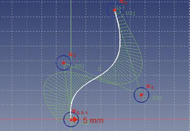

Starting on the part design workbench, create a new project, create a body, and create a sketch in the XY plane. In the blank sketch, make a small closed shape around the origin point. We drew a square and then added some fillets in the corners by clicking the 'create a fillet between two lines or at a coincident point' tool. With the fillet tool selected, click on some corners of the square to add some fillets, and resize them to make an interesting shape. This shape will be the profile of our item we extrude by sweeping it along a path (Figure 6 overleaf). Again, constraining the sketch is unimportant for a simple exploration of the tool.
Close the sketch and then create a new empty sketch in the body. Create this new sketch in the XZ plane. In this sketch, we are going to create the path along which our first sketch profile will be swept. Let's use 'create a B-spline in the sketch' tool. This tool allows us to create a combination of curves in a single line. With the B-spline tool selected, left-click over the origin point in the sketch and pull a line up and to the right or left of vertical, then left-click again and continue with the next line upwards and back towards the centre line. Left-click again and move back out to the right and upwards to create a skewed kind of Z-shape. Left-click to set the next point, and then right-click to finish the B-spline. The two lines you drew should now become curved, and you should see some blue circles. Simply, for now, moving the circles allows you to adjust the curve of the lines. Make a nice swooping curve, such as the one we created (Figure 7).
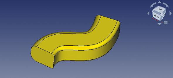
Close the sketch, and in the preview window, you can rotate your view a little and see that the curved edge we created starts at the origin point, which is in the middle of our profile sketch (Figure 8). To sweep the profile along the curved path, highlight the first sketch we made and then click the yellow and red 'sweep a selected sketch along a path' tool. You should see a dialogue box appear in the combo view panel. In the dialogue box, we need to select the path or object along which to sweep. We can do this in a couple of ways. We can either click the 'Object' button under the 'path to sweep along', or we can click the 'Add Edges' button. Having clicked either of these buttons, we can then select the curved path in the preview window. You should now see a brown preview of the profile swept along our path. Click 'OK' to finish the sweep. You should now have a nice swept object in the preview window (Figure 9).
There are many other options in the sweep utility in the part design workbench that can change the way that corners are handled in a swept object, and also how it handles transforming from one profile to another profile over the course of a sweep, which we will
MAKING PIPES
The part design workbench sweep tool creates single solid body objects, but we can apply some techniques we learnt in the last part of this series where we used the 'Create a thickness tool'. As a quick recap, select the face of one end of our swept solid object and click the thickness tool. In the dialogue box, you can set the thickness of the wall structure, and to make it a pipe object open at both ends, click 'Add face' and then additionally select the opposite end of the swept object.
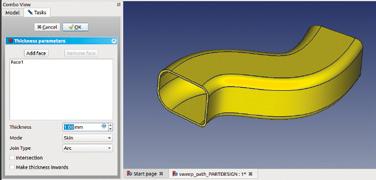
TUTORIAL 90 FreeCAD: let’s get curvy!
Figure 7
A sketch in the XZ plane using the 'create a Bspline' tool
Figure 8
The profile sketch, and the path to sweep the profile along
Figure 9
The completed object with the profile sketch swept along the target path sketch
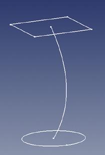
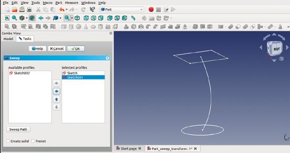
explore on the part workbench shortly. The other thing of note on the part design workbench is that there is a blue and red icon that is the same as the sweep tool we used, except that it's for subtractive sweeps. This means you could draw a solid object and then cut out and remove a swept path through it.
Finally, let’s look at the sweep utilities on the part workbench, which are laid out a little differently. We will also create two profiles and a path, and the profile will be transformed from one shape to the other along the path. Let's create a new project and go directly to the Sketcher workbench. Create a new sketch in the XY plane and then draw a circle anchored around the origin point – it is up to you if you want to constrain it or not for this example. Close that sketch and then create a second sketch, again in the XY plane. In this sketch, let's draw a square – which should be a similar size to the circle we drew in the first sketch – around the origin point. Close this sketch, but highlight it in the combo view panel so that the dialogue box options for the sketch appear below it. We are going to move the position of the sketch so that it shifts vertically 70 mm up the Z-axis. In the sketch dialogue box under the 'Base' heading, open the drop-down menu labelled 'Placement' then, in turn, open the drop-down menu labelled 'Position'. In this menu, change the Z-axis value to 70 mm.
You should be able to see in the preview window that the square is now above the circle. Next, making sure nothing is selected in the file tree, add a third sketch with this sketch drawn on the XZ plane. Using the 'create an edge linked to an external geometry' tool, click the horizontal line that is on the upper square sketch. Next, use the B-spline tool to create a nice curved line which starts at the origin point and curves up to reach the centre of the upper square sketch. Then close the sketch, and you should have three sketches roughly similar to Figure 10
Moving to the part workbench, click the 'utility to sweep' tool. In the dialogue box, you should see the list
Adding
Figure 12
Adding the path that the
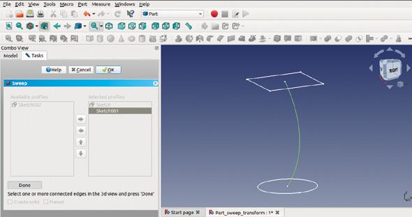
of sketches on the left-hand side. In turn, select the first sketch containing the circle, and click the right-facing arrow that becomes highlighted to move the sketch into the 'selected profiles' column. Repeat this for the second sketch – the sketch that contains the square (Figure 11). Next, click the 'Sweep path' button, and the dialogue box will become greyed out. Click the path you want to sweep along in the preview window to turn it green, and then click the curved path we created earlier (Figure 12). Next, click 'Done' and then click the 'OK' button. You should now see the circle profile has been swept towards the square on our curved path, and it has transformed throughout the curve to conform to the square profile. In the file tree, this is now a 'sweep' object, and double-clicking the sweep object doesn’t allow you to edit the sweep, but rather, opens the dialogue box to move and rotate the part. If you want to change any sweep parameters, you must select the sweep object and delete it, which will return you to just having the three separate sketches, and then repeat the sweep utility process. In the dialogue box for the sweep utility, you can select to make the object a solid; then, you could create a simple copy and then use the thickness and other tools and utilities.
QUICK TIP
When you are drawing the third sketch, the circles will appear exactly on top of the first sketch. To make it easier, make the original sketch invisible by highlighting it in the file tree, toggling visibility by pressing the SPACE bar.
91 FORGE
Figure 10 Three sketches ready for sweeping on the part workbench
Figure 11
the profile sketches in the sweep utility
sweep utility will follow
Create Graphical User Interfaces with Python
✓ Create games and fun Python programs
✓ Learn how to create your own graphical user interfaces
✓ Use windows, text boxes, buttons, images, and more
✓ Learn about event-based programming
✓ Explore good (and bad) user interface design


Buy online: hsmag.cc/pythongui


Get game design tips and tricks from the masters
Explore the code listings and find out how theywork Download and playgame examples byEben Upton
Learn how to codeyour own games with Pygame Zero
This stunning 224-page hardback book not only tells the stories of some of the seminal video games of the 1970s and 1980s, but shows you how to create your own games inspired by them using Python and Pygame Zero, following examples programmed by Raspberry Pi founder Eben Upton.
Available
hsmag.cc/store
now:
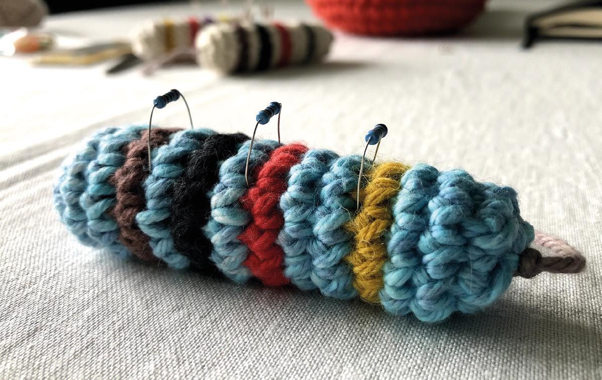
Store spare resistors in a stuffed toy
Crochet a cushion to keep your components safe

hile working on a project, do you find loose resistors lying about willy-nilly (or for that matter, any leggy electronic component) and do you fancy a temporary pad or holder so you can access them quickly and safely? As someone who recently began sewing and crocheting, this author recognised a similar problem with pins and needles. But in the yarn world, we have a solution for that – pincushions! Why not have cushions for electronic components? They can be exceptionally useful for pointy-legged, cryptic resistors with colour codes that are hard to read unless you are bestowed with excellent sight, math wizardry, or a photographic memory! And lo and behold, here’s the first-ever resistor cushion!
WHY CROCHET?
There are many reasons why, but the most important being that crochet’s handiwork, with its code-like patterns and repetitions, give me a sense of safety
and calm. Besides, crocheting is different because you can make 3D objects (aka amigurumi) using just your hands without complex machinery.
In this tutorial, we’ll show you how you can make your own resistor cushion. It is written for absolute beginners who are new to crochet. Towards the end, we’ll walk you through an advanced technique that will make your cushion look super-finished! One more thing: the resistor design is merely an example of my choice, and we encourage you to pursue your own designs for your choice of components!
MATERIALS
Start by choosing a resistor with a colour code of your choice. For the purpose of this tutorial and to make it colourful, I chose the 4.7 kΩ 5% tolerance resistor with a colour code Yellow-Violet-Red-Gold. Now it’s time to purchase your yarn in those exact colours. We recommend 100% soft cotton yarn that works with a crochet hook size of 3.5 or 4 mm (the recommended hook size should be visible on the yarn packaging). You will additionally require cotton stuffing
94 TUTORIAL
@ anu1905
is a post-doc design researcher at Malmo University Above Different sized hooks let you work with different sized yarn
W Anuradha Reddy
Anuradha


to fill the cushion when you are almost finished. This is all you need! Stitch markers and a crochet needle are nice to have, but you can manage without them. Just make sure you have a tapestry needle with a wide enough eye for the yarn to go through, and some safety pins (or hairpins) to replace the stitch markers. You’re good to go!
Before we work the material, a few terms are helpful to follow this tutorial (NB: US crochet terms are used throughout). There are basic crochet stitches such as the chain stitch (ch), single crochet (sc), double crochet (dc), half double crochet (hdc), and so on. Here, we will only use the single crochet stitch (sc). You will also apply crochet techniques like ‘increasing’, ‘decreasing’, ‘changing colour’, ‘working in the round’ and not least, the ‘magic circle’. If you wish to learn the full range of basic stitches and techniques, we highly recommend the Crochet School by Craftyminx (hsmag.cc/CraftyMinx), filled with step-by-step instructions and videos!
MAGIC CIRCLE
You begin by crocheting a ‘magic circle’. There are many ways to do this, as you will notice if you search for ‘magic circle’ or ‘magic ring’ in your browser. In essence, this technique allows you to start ‘working in the round’. You’ll see what this means in just a moment.
Grab yarn that matches your resistor’s base colour and make a loop like an ‘e’. Make sure the working yarn goes over the loose end at the intersection. While holding the yarn in place (use your hand), insert the crochet hook from the middle of the circle and pull


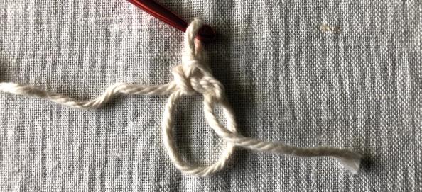
the working yarn from back to front to make a loop around the hook. This is what you would call a ‘yarn over’. Next, while holding the hook in the loop you just made, draw the working yarn again from back to front through the loop and pull tight. Always pull the yarn until your crochet hook feels taut and secure. Now you are ready to start making single crochet (sc) stitches! Insert your hook into the bigger circle again and yarn over by pulling the working yarn from back to front (you should now have two loops around your hook). Draw the working yarn again through the two loops you just created and pull tight. If you did this step correctly, you should see a ‘V’-shaped stitch by the intersection. Congratulations, you successfully made your first single crochet!
• Round 1: 6 sc
Repeat the single crochet stitch five more times. Altogether, you need to make 6 single crochet
95 FORGE
Above
Creating a magic circle to start

stitches, which you can count by identifying 6 V-shaped stitches. Once you have 6 sc, pull the yarn’s loose end all the way until you end up with a circle, or ring, of stitches! You just made a ‘magic circle’. You will use it to ‘work in the round’ and ‘increase’ or ‘decrease’ single crochet stitches for the remainder of the tutorial.
INCREASING
Leaving the yarn’s loose end behind, increase the number of single crochet stitches by doubling each of 6 Vs (6 × 2 =12 sc). It is useful to have a stitch marker (hairpin or safety pin will do) at this point. Start by making one single crochet stitch by inserting your crochet hook below the first V until you have two loops around your hook, and then yarn over. Mark this first single crochet with your stitch marker. Then make another single crochet in the same V to make a total of 2 sc/V. Repeat 2 sc in the second V and 2 more in the third V, and so on. By the sixth V,
you should have 12 sc starting from the stitch marker. This is what it means to work in the round. So far, you completed two rounds.
• Round 2: 12 sc
• Round 3: 12 sc
• Round 4: 12 sc (stop before you complete the 12th sc)
CHANGING COLOUR
While working in the round, if you want to change the colour of the yarn, you always do it at the final stitch before starting a new round. At the end of round 4 i.e. at the 12th sc, start with your base colour until you have two loops around your hook. Then grab the new yellow yarn (the one matching the first band colour of your chosen resistor) and hold it behind the two loops. Then pull the working yellow yarn through the two loops instead of the base colour. Now you can let go of the base colour yarn.
WORKING IN THE ROUND
For the next 15 rounds, continue making 12 sc for every round. In round 3, make single crochets for each of the 12 Vs in round 2. Don’t forget to place your stitch marker in the first V. After 12 scs, continue the same with round 4 until you reach the 12th V, because you will make a colour change here.
TUTORIAL 96 Store spare resistors in a stuffed toy
Above Time
to increase the number of stitches
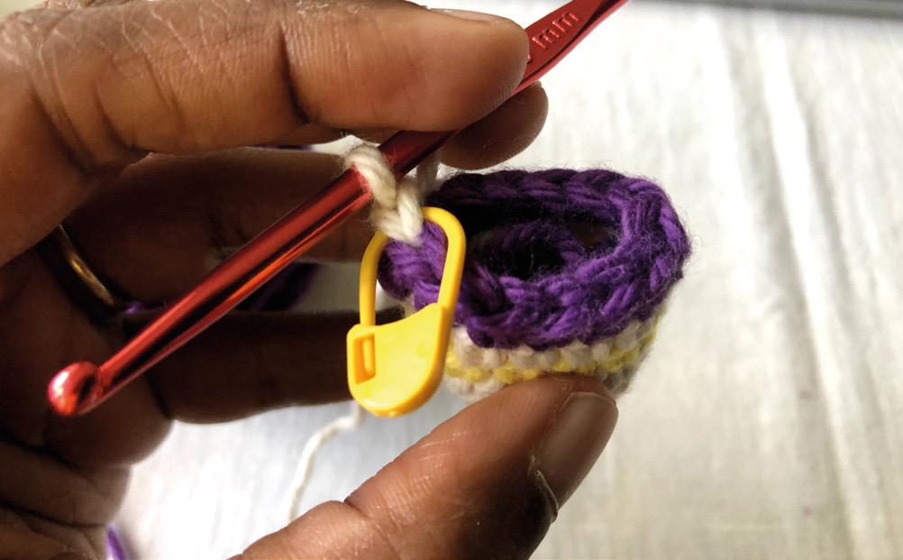

Continue round 5 by making 12 sc with yellow yarn, but remember to switch back to the base colour at the 12th sc. You can cut away the yellow yarn once you have made the switch, and then stuff it inside the resistor. Repeat this pattern until you reach round 15:
• Round 5: 12 sc | Yellow (in the 12th stitch, change to base colour)
• Round 6: 12 sc | Base (in the 12th stitch, change to violet)
• Round 7: 12 sc | Violet (in the 12th stitch, change to base colour)
• Round 8: 12 sc | Base (in the 12th stitch, change to red colour)
• Round 9: 12 sc | Red (in the 12th stitch, change to base colour)
• Round 10: 12 sc | Base
• Round 11: 12 sc | Base (in the 12th stitch, change to gold colour)
• Round 12: 12 sc | Gold (in the 12th stitch, change to base colour)
• Rounds 13 and 14: 12 sc | Base
INVISIBLE JOIN
An ‘invisible join’ is used to create a seamless join when changing colours and crocheting in the round. If you followed the tutorial, you will notice uneven bumps wherever you changed the colour of the yarn. These seams may not be as noticeable in bigger projects, but for our small-sized resistor that requires at least four colour changes, the result looks less than ideal. The invisible join is a clever technique to overcome this, but it is not as intuitive. Once you learn the technique, however, there is no going back!
97 FORGE
Above A marker can help you remember where you are
Left
Use whatever colours you like for your resistor

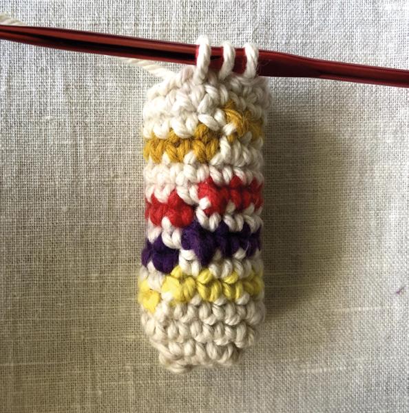
DECREASING
By the end of round 14, your cushion should start to look like the resistor. Now you can stuff the resistor with loose cotton.
To close off the resistor, work the final round by decreasing the number of single crochet stitches from 12 sc back to the initial 6 sc. You will do this by yarning
To finish the resistor, leave about 15 cm of yarn for sewing the ends and cut away
over the first V (two loops around the hook) and then yarning over the second V (now you get three loops around the hook), and eventually pull the working yarn through all three loops of the hook. What’s happening here is that you are reducing two single crochets into one. Repeat the same decreasing pattern until you count 6 sc in the round. Pull tight.
• Round 15: 6 sc
FINISHING OFF
To finish the resistor, leave about 15 cm of yarn for sewing the ends and cut away. Pull the loop all the way through to form a knot.
TUTORIAL 98 Store spare resistors in a stuffed toy
” ”
Above
You have to tie off the end to finish
Below
Don't forget to add stuffing once your resistor is big enough
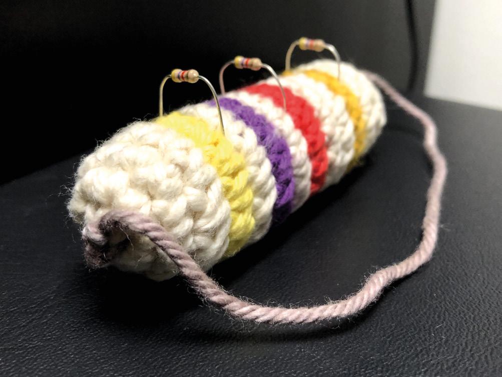
Needle your loose yarn end and sew together the 6 Vs on opposite sides (1–4, 2–5, 3–6) to make sure there are no gaps. Then sew the yarn into the cotton stuffing for a clean finish. It is finally time to pierce some resistors into your resistor cushion, and gloat over your new skill!
If you are not satisfied with your result, don’t be disappointed! Crochet takes practice, like any other skill. However, if you feel ready for a bigger challenge, try the advanced technique called ‘invisible join’ that will make your cushion look super-polished and ready for shop talk!
I will apply the technique used in this video (hsmag. cc/crochet) by Club Crochet called the ‘half-colour change’. To achieve this, you begin as you normally would by inserting your crochet hook below the previous round’s last V stitch, and yarn over until you have two loops around your hook. Then you hold the new colour behind the two loops such that the working yarns of the first (base) colour and the new colour are parallel to one another. Hold both the yarns in such a way that the new colour is on the bottom and
the first colour on top. Then flip the yarns using your fingers so that the new yarn is on top, and pull this yarn through the two loops. Now, flip the yarns back so that the first colour is back on top. (Yes, this can be a bit confusing! Check the video if you need help.)
To start the next round, insert your hook below the next (first) V stitch of the new round. Yarn over by drawing the first colour until you have two loops of different coloured yarns. Flip the two working yarns again so that the new yarn comes on top, then pull through the two loops. This is how you work the half-colour change. Repeat this for the entire colour changing process and you should be able to achieve perfectly straight and clean coloured stripes for your resistor cushion.
Congratulations on braving through, not just your first crochet project, but also your first amigurumi project! You now have the basic knowledge to create your own 3D object in crochet, but we also highly encourage you to pick up on the remaining crochet techniques to have a more versatile skill-base to make anything you want.
99 FORGE
Above The final resistor with additional resistors
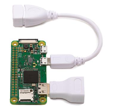
DON’T MISS THE Buy online: store.rpipress.cc magpi.cc/12months FREE PI ZERO W STARTER KIT* With your 12-month subscription to the print magazine SUBSCRIBE FROM JUST £5 > FREE! 3 issues for the price of one > FREE! Delivery to your door > NO OBLIGATION! Leave any time * While stocks last
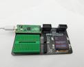


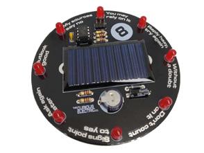
FIELD TEST
CREATE Hacker gear poked, prodded, taken apart, and investigated The easy way to add hardware to Pico 108 PG PICO EXPLORER BEST OF BREED PG 102 Solar power kits Could this be your next soldering iron? 110 PG PINECIL An automatic wood cutter put on test 112 PG OOZNEST CNC
HACK MAKE BUILD
Solar energy solutions and inspirations for your next project
ONLY THE BEST
Solar energy solutions and inspirations for your next project
Free unlimited power is right outside
By Marc de Vinck @devinck
Free energy! It’s a hot topic on many YouTube channels and many pseudoscience websites, but the reality is, there is no such thing as free energy.
That is, unless you are talking about solar energy. OK, yeah, there are upfront costs, but once a system is designed, the energy is freely available from the sun for at least half the day. And that energy can be stored in batteries or capacitors to last through the night.
There are a lot of applications where solar panels make sense. Remote environmental sensors immediately come to mind. A simple microcontroller, sipping just a bit of power from a solar cell, coupled with a few sensors and a LoRa radio, and you could have a long-lasting remote sensor for gathering tons of data for extended periods of time. There are so many possibilities to have LEDs or sensors and actuators running where power isn’t typically available. Think about the shed in your yard, a camping trip, or when you are out on the water.
That’s where solar energy really shines! Sorry for that bad pun.
In this Best of Breed, we’ll start by looking at a few simple solar components for those of you starting from scratch. Then we’ll take a look at a few kits that feature solar power in lieu of disposable batteries or power cords. Something for everyone! And you’ll notice I didn’t cover any generic solar cells. Why? Honestly, there isn’t much to say about a 3 V solar cell, and they can be found on almost any DIY supplier’s site. I’ll be looking at a few of my favourite solar components, unusual solar cells, and kits.
There is no such thing as free energy. That is, unless you are talking about solar energy
BEST OF BREED 102
” ”
Miniature Solar Cell vs Colossal 6 V 9 W Solar Panel
Ilove these solar cells! They are diminutively small and inspiring. I have a handful of them in my studio, but admittedly, I haven’t made anything with them just yet. I have dreams of wearable electronics, mini blinking lights, or power for a miniature, long-term, real-time clock. But do these actually make enough power? Yes, they do!
The BPW34, available at SparkFun, is a tiny PIN photodiode, not a typical solar cell. It can generate power, but is more commonly used to detect light, and is much faster to react than a typical CdS photoresistor. The rated open-circuit voltage is 350 mV, so you will typically use a few to generate enough power when used like a solar cell. SparkFun says they tested four wired in series, and they were able to power an LED. That means the idea of a small, wearable, blinky accessory is definitely possible.

OK, so maybe a ridiculously tiny solar cell isn’t going to work for you. Well then, check out the Colossal 6 V 9 W Solar Panel from Adafruit. These are much more practical for any project that involves a microcontroller, motors, or complex and power-hungry electronics. These panels have an aluminium substrate, making for a much stronger unit than a typical-sized solar cell. Perfect for an outdoor project, or one that might be in a semi-harsh environment. They are waterproof, scratch-resistant, and UV-resistant. Adafruit sells a variety of these panels, so head over to their site to find the best one for your next project.

103 FIELD TEST
SPARKFUN $1.50 sparkfun.com ADAFRUIT $78.95 adafruit.com
Solar
It
much smaller than this!
Solar
When
power, this
it! 9 10 VERDICT / 10 / 10 Left The tiniest solar panel around Below The aluminium substrate is great for tough environments
Miniature
Cell
doesn’t get
Colossal 6 V 9 W
Panel
you need
is
$17.50 adafruit.com
When you start designing your solar-powered project, you will most likely want energy even when the solar panel isn’t generating power, and that requires a battery for storing the energy. That’s where some kind of breakout board to help manage the recharging and distribution of power will really come in handy. The USB / DC / Solar Lithium Ion / Polymer charger from Adafruit works great when pairing one of their solar panels to a lithium-ion or lithium polymer battery. No longer will you worry about losing power at night, or on a cloudy day.
The simplicity of the power management is what makes these boards so popular. Just plug in one of their 6 V solar cells on one side and a compatible 3.7 V/4.2 V battery on the other, and you have a full charging and power management system. Next, you can connect the power leads from your project to the board and you’ve got instant solar or battery power. Just be sure to read all the precautions on their product page, because the specific type of battery and solar panel is really important. And if this version doesn’t work for your specific application, they do have other options available.
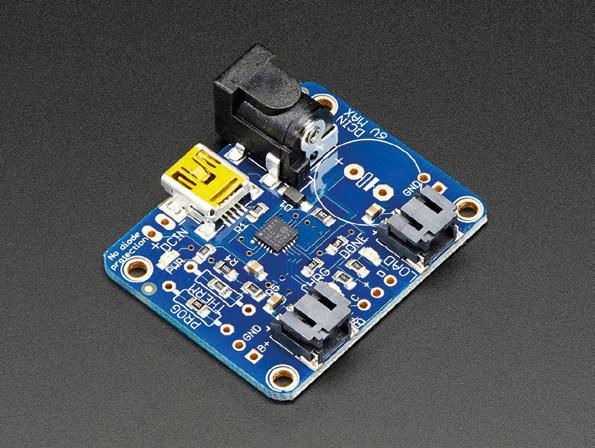
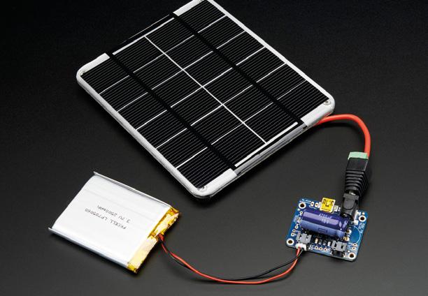
BEST OF BREED 104
USB / DC / Solar Lithium Ion / Polymer charger - v2 USB / DC / Solar Lithium Ion/ Polymer charger - v2 A must-have for most solar projects. 10 VERDICT / 10 ADAFRUIT
Above Get power into your project from almost any source Right Drop this into any device that uses a compatible LiPo Solar energy solutions and inspirations for your next project
Solarbotics SolarSpeeder v2.0
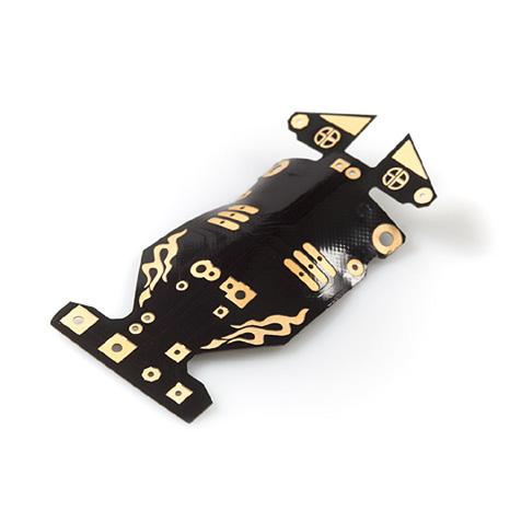
I
remember building this kit many years ago when my kids were still kids. And to this day, it still sits on a shelf in my office. It’s a fun little racer from Solarbotics that was fairly easy to put together, and a lot of fun to race afterwards. Just be ready, because once it’s exposed to light, it will zip away at a fairly speedy pace.
This racer is a bit more complex than it first appears. The SolarSpeeder uses ‘MillerEngine’ technology to charge and power its motor. Don’t worry, that doesn’t make it difficult to use, build, or understand, it just makes it really efficient. More about MillerEngine technology, and the history of solar racers, can be found in the very detailed instructions. Check out the product page for more details.
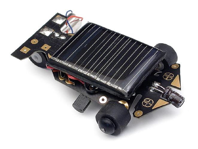
Varies renogy.com
Not all projects revolve around 3.3 or 5 volts. There are a lot of DIY enthusiasts out there working on larger projects, like off-grid housing and the booming #vanlife culture. In those situations, you are most likely looking for large battery storage and sophisticated converters to run lights, refrigerators, and laptops. Renogy’s products range from simple solar panels, to innovative, flexible versions, and engineered systems designed to power an entire house. Head on over to their website and get ready to cut your reliance on the grid!
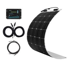
105 FIELD TEST
Solarbotics SolarSpeeder v2.0 Fun to build,
8 VERDICT
SOLARBOTICS $27.50 solarbotics.com Above How far can the sun take you?
RENOGY
and fun after you’ve built it!
/ 10
RENOGY
The Solarbotics Squid Hunting CarouSol Kit
eep-sea adventures don’t typically come up when thinking about solar power, but the folks from the aptly named Solarbotics created their Squid Hunting CarouSol Kit to leverage all that free power from the sun. This kinetic kit is crafted from laser-cut MDF panels, and is powered by a pair of simple solar panels and a few additional electronic components. When the panels are exposed to the sun, it fires right up, and the submarine spins in circles trying to catch the squid. If there isn’t enough light energy to be harvested and used immediately, it will charge

the capacitors – once there is enough energy, it will start to run. Solarbotics says that in a typical office that will happen about once every six minutes. Some simple soldering is required, but even a beginner should be able to put this together without any issues.
Solar 8 Ball Soldering Kit
really like electronic kits that, once assembled, are practical or fun. The Solar 8 Ball Soldering Kit from The Curious Electric Company in the United Kingdom is both! The kit features a standard solar cell and eight LEDs that mimic the randomness of the classic fortune telling 8-ball. Just give it a shake, and through the power of the sun, you will receive your fortune. This is a great first-time solder kit, as the creator has used a socket on the IC, allowing for some error or overheating while soldering, without damaging the fragile IC. It also has a large PCB that is labelled clearly, and the instructions are excellent. You can pick up the kit directly from their website if you are in Europe, and for those US readers, head over to Tindie and check out their shop.
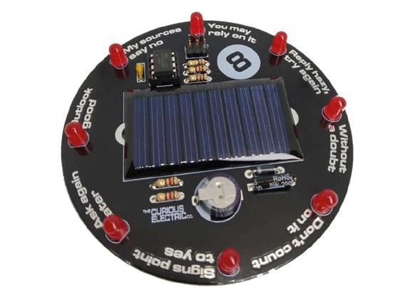
BEST OF BREED 106
Solar energy solutions and inspirations for your next project
I
D
Solarbotics
A fun way to demonstrate solar energy. 9 VERDICT / 10 Solar 8 Ball Soldering Kit A fun kit, even if you’ve never soldered before. 8 VERDICT / 10 SOLARBOTICS $38 solarbotics.com CURIOUS ELECTRIC $15.95 curiouselectric.co.uk
The
Squid Hunting CarouSol Kit
Left
Left Can the sun tell your fortune?
Gently spin around with ambient light

plus all good newsagents and: Inside: Build a four-legged walking robot Create a Tetris-inspired clock Grow veg with hydroponics And much more! WITH GET STARTED Robots, musical instruments, smart displays and more £10 with FREE worldwide shipping MAGAZINE FROM THE MAKERS OF AVAILABLE NOW hsmag.cc/store
Pico Explorer
Expand your Raspberry Pi Pico
PIMORONI £22.20 pimoroni.com
By Ben Everard
B@ben_everard
y now, you can’t have missed the news that there’s a new microcontroller board out – the Raspberry Pi Pico. We’ve looked at some great projects with this in the cover feature this month.
Pimoroni’s Explorer board expands Pico with a small breadboard, a buzzer, four buttons, two slots for breakout boards, two half‑bridge motor drivers, and a 240×240 IPS screen. The board feels solid in your hands, and is styled in Pimoroni’s good looking and user friendly manner.
This hardware is supported by libraries for C/C++ and MicroPython, which you’ll find using this link: hsmag.cc/PimoroniPico. If you look in the examples folder in that GitHub, you’ll find some examples
for how to use the C/C++ libraries, and in the micropython/examples folder, you’ll find details of how to use it with MicroPython. If you’d rather use CircuitPython, Michael Horne’s written up a guide on how to get it all set up at hsmag.cc/PicoExTutorial
At the time of writing, the C/C++ library was documented better (see here: hsmag.cc/PicoExPack), but given that the MicroPython library has methods with the same names shown in the example file, it isn’t particularly difficult to work out what’s going on. The display is perhaps the most complex of the devices to control, and this is done using Pico Graphics (detailed here: hsmag.cc/PicoGraphics). With this library, you can use primitives such as rectangles and circles, and add text. This makes it much easier to use than trying to work with bare pixels.
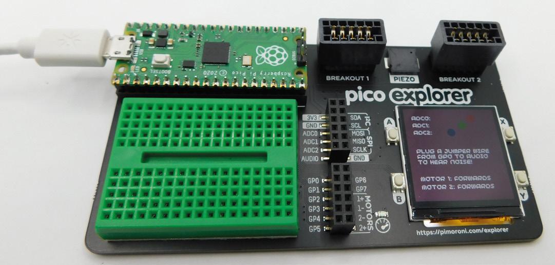
Pico Explorer REVIEW 108
Right Everything fits together on one small circuit board
The four buttons positioned around the edge of the screen can be used to control a user interface, or for games. While four buttons is enough to let you have quite a bit of control, if you need more, you can always add some using the GPIOs.
The only slight oddity about the hardware is that the buzzer isn’t connected to a GPIO pin. Instead, it’s connected to a header. To use it, you have to use a jumper wire to connect it to a GPIO. Which one you use is up to you, which has the advantage of not tying up a GPIO when not in use.
IN USE
By adding extra hardware, some of the GPIO pins on Pico are taken up. This means that there are only seven, plus three analogue inputs available, plus one I2C, and one SPI bus for you to add extra hardware to. This is quite a bit of connectivity and should be plenty for most uses, but represents just over half of what is available on a bare Pico.
If you want to get started with Pico, but don’t quite know what you want to do with it yet, then the Explorer is a great option. There’s loads to play with and loads of further options to slot into the two breakout slots. Environment monitoring setups and robots are just a couple of the things we’d imagine people creating with this setup. However, games seem to be a popular target for people who have got the board so far. Despite the board only being available for a few weeks, we’ve already seen Tetris (hsmag.cc/PicoTetris) and Snake (hsmag.cc/PicoSnake), and we expect to see many more over the coming weeks and months.
The motor drivers can be used to power any high current device, not just motors. Bright LEDs and other power hungry components can also be hung off these outputs. They’re controlled by a DRV8833 driver, and the data sheet lists 1.5 A as the maximum output current, but there’s also a handy over current LED to
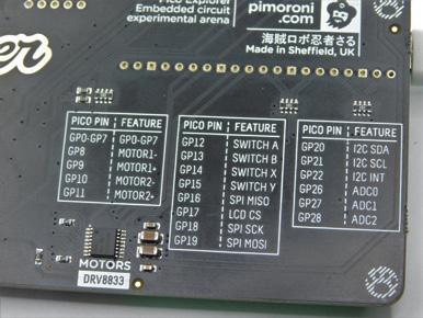

let you know if you’re pushing it too far. Also be aware of the limits of your power supply if you’re planning on driving both outputs hard.
The one omission from this board is that there’s no access to 5 V power. Only the 3.3 V power is available to the user. Since Pico’s inputs are 3.3 V, most of the time you want to power external hardware with 3.3 V as well, but there are some cases where this isn’t enough. For example, attaching WS2812B LEDs (aka NeoPixels): there’s no easy way to do that with this board. Of course, not having 5 V output does have the advantage of making it that much harder for a careless user to accidentally kill their Pico, so while it is a limitation, it may be a sensible one.
It should come as no surprise that a board called ‘Explorer’ is great for learning more about Pico and testing it out in different situations. Pimoroni compares this kit to the ‘all in one’ electronics kits that some readers may be familiar with from the 1980s and 1990s. And there are certainly similarities: this kit provides you with some base hardware that you can use in different ways to make different projects.
This kit gives you a lot of the ‘glue’ that makes it easy to connect different hardware to your Pico, whether that’s sensor breakouts, high powered devices, or through hole components. It turns Pico into a plug and play kit that you can take as far as you like. If you’re more comfortable with code than with hardware, you can do a lot without having to worry about wiring things up. When you want to go a little further, you can expand your projects with your own circuits.
FIELD TEST 109 VERDICT The
to expand your Pico. 9/ 10
easy way
Left
The 240×240 IPS screen is great for detailed graphics
Below There’s a handy table to let you know which GPIOs connect to what hardware
Pinecil soldering iron
By Jo Hinchliffe
The Pinecil is an open-source, portable soldering iron built around a 32-bit RISC-V chip with a raft of features and a low price. It’s similar in appearance and operation to the popular TS100 soldering iron.
Whilst this isn’t solely a comparison or ‘versus’ review, it’s always going to get compared to the TS100 as it has some shared attributes being sold as ‘TS100-compatible’.
Out of the box, the Pinecil feels nice in the hand, and loosening the upper screw at the front end allows the tip/element to slide in easily. There’s a blue rubber collar at the business end of the body that makes it feel very comfortable and secure in-hand. The supplied tip is a pointed tip, type B2, which is a fairly wide, general-purpose tip. Any tip designed for the TS100 will fit into the Pinecil, and these are available widely online and on the Pinecil webpage. Also on the Pinecil page, you can buy spare shells and rubber grips in the standard black/blue combo or, currently, a red version.

It’s slightly larger than the TS100 and, whilst this doesn’t make a huge difference in-hand, it does have a couple of benefits. Being slightly wider and having some small feet at the tip end of the body, the Pinecil is much more stable laid on a desk. We would recommend using a stand of course, but with these feet, you could get away without one. It’s not immediately apparent until viewing side by side, but the Pinecil also has a fractionally larger OLED display than the TS100.
All screws on the Pinecil are small Phillips screws and, like the TS100, it has a small screw to the rear of the body enabling a ground strap to be connected. As we move to the back of the Pinecil body, we can see it has a USB-C socket and a barrel jack connector. This introduces one of the things the Pinecil has done well – it has a wide range of options to power it. Obviously, you can use a USB-C supply and it is compatible with PD 3.0 and QC 3.0, meaning many
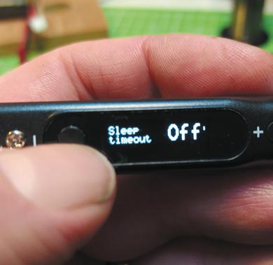
REVIEW 110 Pinecil soldering iron
Below At power on, a single button press and the iron heats up in a few seconds to the userset temperature Right The menu items are all pretty selfexplanatory and well laid out. The simple two-button interface works really well
Does a soldering iron need to be smart? PINE64 $34.99 pine64.com
@concreted0g
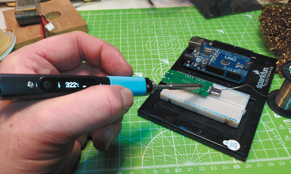
users may have a phone/tablet/laptop USB-C supply that will work. Of course, this also means that USB-C PD/QC power banks can also be used. The barrel jack opens up further options, similar to the TS100. A common method is to use a laptop power supply rated between 12 and 24 V, capable of delivering up to 3 amps. You can also run the Pinecil off LiPo batteries within the voltage range, so between three-cell and six-cell LiPos, making this exceptionally useful for portable ‘in the field’ work.
Powering on the device, we are met with the Ralim operating system, which began life as a popular alternate open-source firmware for the TS100. It’s pretty intuitive that on power-up you can click the ‘+’ button to heat the iron and begin soldering, or you can click the ‘–’ button to enter the menu system. You can adjust lots of parameters in the menu system and, in case you get a bit lost in the changes, you can revert to factory settings. There are settings to adjust the length of time before the iron goes to sleep, adjustments for the motion detection for sleep/ wake and idle temperature, and much more. As the reviewer is left-handed, it’s excellent that you can swap the orientation of the display, or even set it to automatically detect and select orientation.
We were lucky to receive a Pinecil from the first production run, which came with a free Pinecil breakout board – which is a little PCB with male and female USB-C sockets. When connected, this breaks
out the JTAG header, UART, USB, and other pins, allowing people to tinker with firmware and other projects. The board is supplied pre-populated, but header pins aren’t soldered into place so, as the first test job, we set about soldering these in.
This is a brilliant soldering iron that works extremely well at an astonishingly good price
In use, the iron heats up extremely quickly, and a one-handed operation to adjust the temperature is easy. The new tip tinned well with some solder, and it worked perfectly to solder the through-hole header pins. We felt that the B2 tip was too broad for SMD work, but upon swapping it for a finer-pointed TS-I tip, the Pinecil worked excellently to solder some 0805 resistors and an LED to a PCB.
To sum up, this is a brilliant soldering iron that works extremely well at an astonishingly good price. It excites us that the $35 (currently reduced to $25) price tag puts the Pinecil in an affordable position for beginners. This sets up those new to soldering with a high-quality tool that’s far better than what many seasoned solderers started with.
VERDICT
Excellentquality iron, with a fabulous ground-breaking feature set at this price point.
FIELD TEST 111
9 / 10
Above Using the Pinecil and the supplied B2 tip to solder some header pins
” ”
Ooznest WorkBee CNC Machine Kit
Automate your woodwork
By Daniel Hollands
One of the core aspects of software development, especially for tasks which are repeated on a regular basis, is automation, i.e. scripts or tools that complete tasks for you. This reduces human error, gives you more speed and efficiency, and frees up time to do other work.
We mention this because this reviewer is a software engineer by day, and a hobbyist woodworker by night. A CNC router is something which perfectly bridges these two very different worlds by allowing automation to enter the realms of woodworking, providing many of the same benefits.

The CNC we’re talking about today is the WorkBee by Ryan Lock, an open-source design which builds on the prior OX CNC Machine design by Mark Carew. It is sold as a kit by Lock’s company, Ooznest, comes in six sizes ranging from 500×500 mm to 1500×1500 mm, and features options on connectivity (WiFi or Ethernet), choice of router (Katsu, Makita, and DeWalt), and design software (Cut2D, VCarve, and Aspire, all by Vectric), along with some optional extras. The machine reviewed is the 1000×1000 mm WiFi, with the VCarve Pro software, DeWalt router, and all the optional extras, which cost £2575.
When the kit arrived, we were filled with a mix of joy and anxiety. Joy at all the exciting things we could make, and anxiety at the sheer quantity of parts we had to assemble.
It turns out we needn’t have worried, as while the parts are numerous, the online documentation system is excellent, featuring step by step guidance and good quality images which help enhance your understanding of the instructions. We did notice one or two small errors and omissions, but these are quick to be identified via the built-in comment system, populated with help and suggestions by other customers.
The build, which requires a small selection of Allen keys, a couple of spanners, and a screwdriver (none of which are supplied) took this reviewer eight evenings over a period of about two weeks, although it probably could be done in a single weekend, had the time been available.
The build was uneventful, barring three minor exceptions. The first was this reviewer’s own fault for not following the instructions correctly, and was easy to resolve once he’d figured that out. The second was the trouble he had attaching the spoilerboard to the
REVIEW 112 Ooznest WorkBee CNC Machine Kit
Below Close-up of the router, featuring optional dust shoe
OOZNEST From £1245.00
ooznest.co.uk
@makerRIP
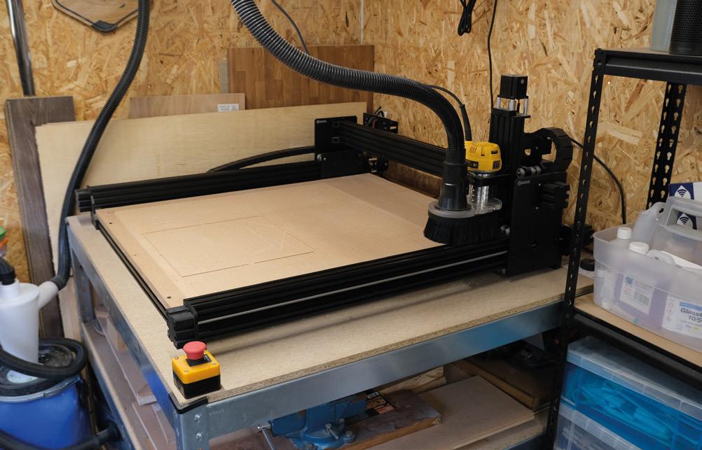
frame, which is a quirk of the design, but thankfully doesn’t need to happen that often. And the third was an issue with the Z-axis failing to home correctly, about which we contacted Ooznest. They were quick to diagnose an issue with the limit-switch and posted a replacement part to us before the day was out. In fact, now would be a good time to mention just how good Ooznest customer service is as, on every occasion we spoke with them, they’ve been very helpful, often bending over backwards to assist.
With the machine fully constructed, we set about running the first job, that of ensuring the spoilerboard was parallel by surfacing it. This was the first time we had set a job on the machine, so were happy to find that Ooznest had a video on their YouTube channel (one of many other such videos) explaining exactly what to do, which made it far less intimidating.
The machine is controlled by an intuitive browserbased interface, into which you upload the G-code generated by your CAD/CAM software, which in our case was VCarve. Although this isn’t a review of VCarve, we will take a moment to mention that, while the interface looks a bit intimidating at first glance, we found it quick and easy to learn the functionality we needed, even if we are barely scratching the surface of what the software is capable of. We’re just disappointed it’s not available for macOS.
Having used the machine for a couple of months now, we can tell it’s a solid piece of kit and very much beloved by the legion of WorkBee owners we’ve connected with since buying it. Dust collection is an absolute must, so you’ll need to invest in a Shop-Vac if you don’t already have one and, for this reason, we recommend including the dust shoe in your configuration. We were disappointed that the end mill
Dust collection is an absolute must, so you’ll need to invest in a Shop-Vac if you don’t already have one
starter kit didn’t come with any v-bits, but otherwise, the selection provided let us hit the ground running. We’ll finish the review by mentioning there are a fringe of woodworkers who turn their noses up at CNC machines, claiming it’s not real woodworking if the machine is doing all the work. Obviously, we disagree with this stance, and retort that a CNC is just another tool that adds to the arsenal of what can be done, not a magic box which does it all for you. This reviewer is very happy to have the WorkBee as part of his workshop and he’s looking forward to putting it to work in many future projects.
An excellent piece of kit for any hobbyist woodworker.
FIELD TEST 113 VERDICT
9 / 10
Above
The machine takes up a full quarter of my workshop
” ”
DON’T MISS OUT ALSO MUSIC FREECAD LASER CUTTING RASPBERRY PI PICO AND MUCH MORE ON SALE 18 MARCH hsmag.cc/subscribe BUDGET
3D PRINTING
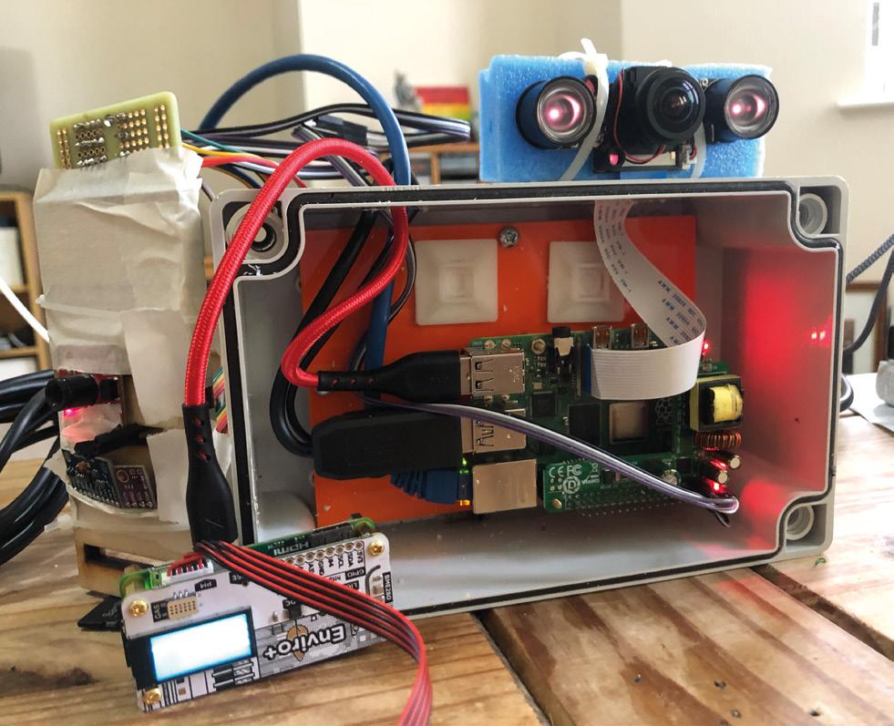
A Raspberry Pi 4, Pimoroni Enviro+ with particulate matter sensor, IR camera, battery, and a bit of custom circuitry keep an eye on the bees living atop The Tapestry building in the centre of Liverpool.