
SKID STEER LOADER
SB2334E04 0510
440 Plus 460 Series 470 Plus
Do not start, operate or service this machine unless you have read and understood these instructions and received proper training.
Unsafe or improper use of the machine may cause serious injury or death.
Operators and maintenance personnel must read this manual and receive training before operating or maintaining the machine.
This manual should be kept with the machine for reference and periodically reviewed by the machine operator and by all personnel who will come into contact with it.
The following warning is provided pursuant to California Health & Safety CodeSections 25247.5 et, seq,
California Proposition 65
WARNING WARNING
Engine Exhaust, some of its constituents, and certain vehicle components contain or emit chemicals known to the State of California to cause cancer birth defects of other reproductive harm.
Battery posts, terminals and related accessories contain lead and lead compounds, chemicals known to the State of California to cause cancer and birth defects or other reproductive harm.
WASH HANDS AFTER HANDLING.
FOREWORD
• This manual explains the safety rules, lubrication, testing and controls to operate and maintain the DOOSAN Skid Steer Loader for safe and optimal performance.
• The operator should be familiar with all of the contents of this manual before starting the vehicle to insure maximum performance, safety and economy.
• Descriptions explain the testing, starting, operation, and stop procedures in detail.
• To maintain the vehicle in top condition, the operator should periodically check the vehicle in accordance with the service schedule.
• The periodic maintenance intervals in this manual are based on the service hour meter.
Environment Management
Note that DOOSAN Infracore is ISO 14001 certified which is harmonized with ISO 9001Periodic ENVIRONMENTALAUDITS & ENVIRONMENTALPERFORMANCE EVALUATIONS have been made by internal and external inspection entities. LIFE - CYCLE ANALYSIS has also been made through out the total product life. ENVIRONMENTMANAGEMENTSYSTEM includes DESIGN FOR ENVIRONMENTfrom the initial stage of the design.
ENVIRONMENTMANAGEMENTSYSTEM considers environmental laws & regulations, reduction or elimination of resource consumption as well as environmental emission or pollution from industrial activities, energy saving, environment - friendly product design(lower noise, vibration, emission, smoke, heavy metal free, ozone depleting substance free, etc.), recycling, material cost reduction, and even environmentally oriented education for the employee.
S-1
SAFETYINFORMATION
This is the safety-alert symbol.
When you see this symbol on your machine or in this manual, be alert to the potential for personal injury. Follow recommended precautions and safe operating
practices HA0OA00I S-2
SIGNALWORDS
Asignal word - DANGER, WARNING, OR CAUTION - is used with the safety-alert symbol.
DANGER: Indicates an imminently hazardous situation which, if not avoided, will result in DEATH or SERIOUS INJURY.
WARNING: Indicates a potentially hazardous situation which, if not avoided, COULD result in DEATH or SERIOUS INJURY.
CAUTION: Indicates a potentially hazardous situation which, if not avoided, MAYresult in INJURY.
ATTENTION: Indicates potential machine damage if a certain procedure is not followed.
IMPORTANT: Indicates information an operator should know to prevent minor machine damage if a certain procedure is not followed.
DANGER
WARNING CAUTION
ATTENTION IMPORTANT
S-3
IACOA00I
WARNING
SAFETYINSTRUCTIONS
Carefully read all safety messages in this manual and all safety labels on your machine. Keep safety labels in good condition. Replace missing or damaged safety labels. Be sure new equipment components and repair parts include the current safety labels. Learn how to operate the machine and how to use controls properly. Do not let anyone operate the machine without instruction. Keep your machine in proper working condition. Unauthorized modifications to the machine may impair operator safety and well being and/or machine life and function.
DANGER
SAFETYRULES
• ONLYtrained and authorized personnel should operate and maintain the machine.
• Use common sense and follow all safety rules, precautions and instructions when operating or performing maintenance on the machine.
• When working with another person, be sure all hand signals to be used are understood.
• Certain operating conditions may require reference to applicable OSHA, ANSI, ISO, EEC or other local and national regulations. Consult your supervisor or safety coordinator to be sure all applicable standards are being followed, and for special operating conditions.
• Never operate equipment under the influence of drugs or alcohol. Certain prescription and over-thecounter medications can affect alertness and coordination. Follow instructions on labels and/or consult your physician. Notify your supervisor or consult your physician for clarification.
S-4
WARNING CAUT ON CAUTION
HA0OA01I
CONTENTS 1.0. OWNER/OPERATOR SAFETYOVERVIEW 1.1.Safety Message for Owners and Operators..........................................................................................1 1.1.1.Owner/Employer Responsibility................................................................................................1 1.1.2.Operator Responsibility..............................................................................................................2 1.2.Maintaining a Safe Workplace................................................................................................................3 1.3.Matching the Machine to the Job..........................................................................................................4 1.3.1. Warning Signal Options..............................................................................................................4 1.3.2.Modifications..............................................................................................................................4 1.4. Maintenance Practices..........................................................................................................................5 1.5. Operator Safety Training........................................................................................................................5 1.5.1. Formal Training..........................................................................................................................5 1.5.2. Inspection Training....................................................................................................................6 1.5.3. Training Program Development................................................................................................6 1.5.4. Practical Training........................................................................................................................7 1.5.5.Recognition................................................................................................................................7 1.6. Information Resources for Operation, Maintenance, and Safety..........................................................7 2.0. SAFETYINFORMATION 2.1. Safe Operating Practices........................................................................................................................9 2.2. Rated Operating Load Plate................................................................................................................11 2.3.Safety Warning Label Locations and Descriptions..............................................................................12 2.3.1. Label Locations........................................................................................................................12 2.3.2. Label Descriptions....................................................................................................................13 2.4. General Safety and Hazard Information..............................................................................................18 S-5
2.4.1.Unauthorized Modification......................................................................................................18 2.4.2.Clothing and Personal Protective Items..................................................................................18 2.4.3. Mounting and Dismounting......................................................................................................19 2.4.4. Fire Prevention and Hazardous Fluids and Vapors................................................................20 2.5.Operating Safety..................................................................................................................................21 2.5.1. Work Site Safety......................................................................................................................21 2.5.2. Operator’s Cab........................................................................................................................22 2.5.3. Safe Operating Practices........................................................................................................22 2.5.4. Ventilation for Enclosed Areas................................................................................................23 2.5.5. Flammable and Explosive Atmospheres..................................................................................23 2.5.6. Precautions for Mirrors, Windows, and Lights........................................................................24 2.5.7. Ensuring Visibility....................................................................................................................24 2.5.8. Traveling in Reverse, Safe Working Zone..............................................................................25 2.5.9.Avoiding High-Voltage Cables..................................................................................................25 2.5.10. Operating on Snow..................................................................................................................26 2.5.11.Working on Loose Ground......................................................................................................26 2.5.12.Preventing Crushing or Cutting................................................................................................27 2.5.13.Parking....................................................................................................................................27 2.5.14.Precautions for Attachments....................................................................................................28 2.5.15.Precautions for Loading and Emptying the Bucket..................................................................28 2.5.16.Precautions for Stopping the engine........................................................................................29 2.6.Maintenance Safety..............................................................................................................................30 2.6.1.Periodic Maintenance..............................................................................................................30 2.6.2. Precautions for High Temperature Operations........................................................................31 2.6.3.Maintaining and Inspecting Hydraulic Equipment....................................................................32 2.6.4. Precautions for High Pressure Oil............................................................................................33 2.6.5. Preventing Battery Hazards....................................................................................................34 2.6.6. Waste Material Precautions....................................................................................................35 S-6
MACHINE
2.6.7. Rotating Fans and Belts..........................................................................................................35 2.6.8. Tire Maintenance......................................................................................................................36 3.0. SERIALNUMBER LOCATIONS 3.1.Vehicle Serial Number..........................................................................................................................37 3.2.Engine Serial Number..........................................................................................................................37 4.0.
COMPONENTS 4.1.Identification of Machine Parts............................................................................................................39 5.0. CONTROLS AND INSTRUMENTS 5.1.Instrument Panel ..................................................................................................................................41 5.2.Controls ..............................................................................................................................................45 5.2.1.Drive Control Lever ................................................................................................................45 5.2.2.Pedals ....................................................................................................................................46 5.2.3.Boom Pedal ............................................................................................................................46 5.2.4.Bucket Pedal ..........................................................................................................................47 5.2.5.Auxiliary Hydraulics Thumb Control ........................................................................................47 5.2.6.Engine Control ........................................................................................................................48 5.2.7.Seat Bar ..................................................................................................................................49 5.3.Controls (Joystick : Option) ................................................................................................................50 5.3.1.Drive Control Lever ................................................................................................................51 5.3.2.Boom & Bucket Handle............................................................................................................52 5.3.3.Auxiliary Hydraulic Thumb Control..........................................................................................53 5.3.4.Engine Control Joystick............................................................................................................55 S-7
6.0. OPERATING INSTRUCTIONS 6.1.Inspection Before Boarding ................................................................................................................56 6.2.Boarding the Loader ............................................................................................................................56 6.3.Starting..................................................................................................................................................57 6.4.Traveling and Steering ........................................................................................................................59 6.5.Traveling and Steering (Joystick : Option)............................................................................................61 6.6.Operation ............................................................................................................................................62 6.7.Traveling on a Slope, Parking ............................................................................................................64 6.8.Towing Procedures ..............................................................................................................................66 6.9.Lifting..................................................................................................................................................67 6.10.Transportation ......................................................................................................................................68 6.11.Bucket and Attachments ......................................................................................................................69 6.12.Boom Lock Operation..........................................................................................................................72 7.0. PERIODIC MAINTENANCE 7.1.Safety Warnings....................................................................................................................................74 7.2.Access to Items Requiring Service ......................................................................................................75 7.2.1.Rear Door and Engine Hood ..................................................................................................75 7.2.2.Canopy Tilting ..........................................................................................................................76 7.3.Daily Pre/Post Start Checks ................................................................................................................77 7.3.1.Pre-Start Checks......................................................................................................................77 7.3.2.After Starting-Before Operation................................................................................................78 7.4.Service Schedule ................................................................................................................................79 7.5.Lubrication Points ................................................................................................................................81 7.6.Operator Restraint Lubrication and Maintenance ................................................................................86 7.6.1.Lubrication ..............................................................................................................................87 7.6.2.Function ..................................................................................................................................87 S-8
7.7.Engine Lubrication ..............................................................................................................................88 7.7.1.General....................................................................................................................................88 7.7.2.Draining Engine Oil..................................................................................................................89 7.7.3.Remove/Replace Engine Oil Filter..........................................................................................91 7.8.Engine Cooling System........................................................................................................................91 7.9.Fan Belt................................................................................................................................................92 7.9.1.Belt Tension..............................................................................................................................92 7.9.2.Adjustment................................................................................................................................92 7.10.Two Stage Air Filter..............................................................................................................................93 7.10.1.Removal-Primary Element......................................................................................................93 7.10.2.Removal-Secondary Element..................................................................................................94 7.10.3.Installation................................................................................................................................94 7.11.Spark Arrestor......................................................................................................................................94 7.11.1 General....................................................................................................................................94 7.11.2 Maintenance............................................................................................................................95 7.12.Battery..................................................................................................................................................95 7.12.1.Remove and Install..................................................................................................................95 7.12.2 Jump Starting the Loader........................................................................................................96 7.13.Fuel System/Filters..............................................................................................................................97 7.13.1.Removal/Installation-Fuel Filter,Water Separater....................................................................98 7.13.2.Fuel Tank Drain........................................................................................................................99 7.14.Priming the Fuel System....................................................................................................................101 7.14.1.Bleeding the Fuel System......................................................................................................101 7.14.2.Draining the Water................................................................................................................103 7.14.3.Cleaning Fuel Strainer............................................................................................................104 7.15.Hydraulic System Maintenance..........................................................................................................106 7.15.1.Oil Level Indicator..................................................................................................................106 S-9
7.15.2.Filter Replacement................................................................................................................107 7.15.3.Hydraulic Fluid Replacement................................................................................................108 7.16.Chain Case Drain and Refill..............................................................................................................109 7.17.Parking Brake Adjustment..................................................................................................................110 7.18.Tire Maintenance................................................................................................................................111 7.18.1.General Information................................................................................................................111 7.18.2.Inflation Pressures..................................................................................................................111 7.18.3.Installation and Removal........................................................................................................111 8.0. DIMENSIONAL& PERFORMANCE SPECIFICATION 8.1.Dimensional Specifications................................................................................................................112 8.2.Operational Specification (Per SAE J732 Feb 80)............................................................................116 8.2.1.Performance..........................................................................................................................116 8.2.2.Power Unit..............................................................................................................................117 8.2.3.Final Drive Components........................................................................................................118 8.2.4.Hydrostatic Transmission Pump............................................................................................119 8.2.5.Hydraulic System..................................................................................................................120 8.2.6.Electrical Components..........................................................................................................123 8.2.7.Instrument Features..............................................................................................................124 8.2.8.Seat........................................................................................................................................124 8.2.9.Noise......................................................................................................................................124 8.2.10.Fluid Capacities & Specifications . . . . . . . . . . . . . . . . . . . . . . . . . . . . . . . . . . . . . . . . . . .. . . . . . . . . . . . . . . . . . . . . . . . . . . . . . . . . . . . . . . .125 • ENVIRONMENT PROTECTION SECTION . . . . . . . . . . . . . . . . . . . . . . . . . . . . . . . . . . . . . . . . . . . . . . . . . . . . . . . . . . . . . . .. . . . . . . . . . . . . . . . . . . . . . . . . . . . .126 S-10
1. OWNER / OPERATOR SAFETYOVERVIEW
1.1. Safety Message for Owners and Operators
Your DOOSAN equipment has been designed with the safety of the persons who will operate and service it in mind. However, our care in designing this equipment does not guarantee that it will be used in a safe manner. Safe operating practice is where your responsibility and the responsible actions of the persons who operate this equipment take over.
1.1.1. Owner/Employer Responsibility
Both the Occupational Safety and Health Act (OSHA) and the American National Standards Institute (ANSI) make you, the employer, responsible for providing formal training and a safe workplace environment for the use of this equipment.
Your responsibility also includes establishing daily inspections and scheduled maintenance practices to ensure the equipment’s ongoing safe operating condition.
The manual you are reading now is intended to help you meet your responsibilities. It identifies warning labels on the equipment and explains what they mean. It describes some of the general and specific hazards to be aware of when operating the equipment.It also offers some suggestions for establishing workplace rules and operator training programs.
As the owner/employer, you also have the responsibility to be certain that the equipment you have placed into service is capable of doing its intended job.
- 1 -
This includes matching equipment design to working conditions, capacity to the size of loads it will be handling, and selecting suitable attachments and options. This section of the manual discusses these issues as well.
At the end of this overview, we list specific OSHA, ANSI, and other published resources you can consult for ways to help you comply with safety requirements for the use of this equipment in your workplace.
1.1.2. Operator Responsibility
If your job includes operating this equipment, you should first get formal training in how to operate it properly and safely. Furthermore, you should ensure that your workplace is maintained to assure your continued safety and the safety of others around whom you work.
In addition, you, the operator, have the responsibility to :
• Follow the safety practices in which you are trained - every day.
• Recognize and avoid potential hazards in your workplace.
• Understand and abide by the Warning labels attached to the equipment.
• Inspect the equipment for its serviceability at the beginning of each shift.
• Report immediately any service problems you notice before you use the equipment or that develop while you are using it.
• Report immediately any unsafe workplace conditions that threaten your safety or the safety of others.
• Avoid horseplay or other reckless actions that you know endanger yourself or others.
In short, every operator of this equipment has the responsibility to use common sense at all times and to make safety his or her number one job priority.
- 2 -
1.2. Maintaining a Safe Workplace
As we said, operators should recognize and avoid hazards in the workplace. Although some injuries occur because of unsafe operating practices, many result from unnecessary workplace hazards. To maintain a safe workplace environment for this equipment, do the following:
• Remove physical hazards where the equipment will be operated, in either the plant or the yard.
• Separate pedestrian and equipment traffic wherever possible.
• Place convex mirrors at blind intersections.
• Require the use of horns at intersections or when approaching pedestrian areas.
• Establish equipment speed limits.
• Install and maintain backup alarms and flashing caution lights on equipment.
• Use edge guards, levelers and trailer locks on docks.
• When the equipment is driven onto trailers, use wheel chocks and jack supports if necessary to prevent creeping and possible collapse.
• Develop - and enforce - workplace safety rules for all employees.
• Post these rules conspicuously in the areas where they apply.
Many appropriate workplace rules are published by OSHA, ANSI, and the National Safety Council. (See the list below under “Information Resources for Operation, Maintenance, and Safety.”) We recommend that you consult these publications as you develop and update the safety rules for your workplace.
- 3 -
1.3. Matching the Machine to the Job
Every employer and operator should ensure that equipment is properly suited to the job it must perform. It should be selected with conditions and capacity well in mind, otherwise operators and other workers may face hazards resulting directly from wrong equipment selection. Furthermore, equipment suited for one job or environment may not be suitable at all when moved to a different work area.
1.3.1. Warning Signal Options
ANSI requires audible or visual alarms in high noise or low lighting environments, or in areas where pedestrians and equipment intermix. Your DOOSAN dealer can provide effective warning signal devices to meet the conditions of your application.
1.3.2. Modifications
Equipment should be used for its intended purpose only. For example, lift truck forks and skid steer loader buckets should never serve as man-lifts or mobile work platforms.
Many times the addition of a special attachment can affect the ability of equipment to operate at the capacity originally intended. When modifications potentially change equipment safety, OSHAand ANSI require you to obtain written approval from the manufacturer. If a modification changes a machine’s capacity, the machine’s capacity plate must also be changed. Consult your DOOSAN dealer before making modifications to your equipment.
- 4 -
1.4. Maintenance Practices
Well maintained equipment is safer equipment. Aregular program of scheduled maintenance should be part of your facility’s ongoing safety program. Daily inspections or inspections at the start of every shift are required by OSHA. Your DOOSAN dealer can help you train your operators for this task and provide you with genuine replacement parts and service equipment when scheduled (or unscheduled) maintenance and repairs are needed.
Although operators have a daily responsibility to inspect and report service problems, OSHA and ANSI standards require that equipment maintenance and repair be performed by authorized mechanics only. Understand what is reasonable to expect in this area, and leave the serious maintenance and repair tasks to professional mechanics and technicians.
1.5. Operator Safety Training
Although this manual contains much information about safety practices, it is not meant to be a training manual for new operators. An employer’s responsibility extends beyond handing an employee this or any other document and saying “read this to learn how to operate this equipment.”
1.5.1. Formal Training
OSHAand ANSI require formal training for new operators and refresher training for experienced operators, along with appropriate on-the-job supervision. Furthermore, training must be tailored to the specific conditions of your workplace and the workplace rules you have developed to protect your employees. Whenever work conditions change in ways that affect operator safety, training for the new conditions must be provided.
- 5 -
Of course, before any employee can be selected to operate industrial or construction type equipment, the employee must meet the employer’s specific visual, auditory, physical and mental ability standards.
1.5.2. Inspection Training
OSHAfurthermore requires that operators be trained to conduct daily equipment safety inspections. The goal of these inspections is to prevent any piece of equipment in need of repairs from being placed into service and thereby endangering personnel. Your DOOSAN dealer can help you develop training to comply to this and to other OSHA/ANSI requirements.
15.3. Training Program Development
As noted above, OSHA/ANSI requires your training to be designed around the conditions present in your operation.
To ensure this, ask yourself specific questions:
• In what areas of our workplace does operating the equipment pose hazards to pedestrians?
• What hazards must operators be trained to deal with?
• Does our workplace have any one-way aisles, speed zones, high noise, low light, or fire hazard areas?
• What are the specific features of our loading docks, ramps, or railcar loading facilities?
• What specialized attachments are used on our equipment?
• What personal protective equipment or special clothing is necessary to operate the equipment in our work environment? (hard hats, seat restraints, respirators, protective shoes or gloves, etc.)
• Are operators conducting daily inspections prior to shift start?
• Does our equipment require any special refueling procedures?
- 6 -
One additional recommendation: ask those employees who work around (but do not operate) the equipment for suggestions about what the operators should be taught.
1.5.4. Practical Training
The questions above and others like them can help you design an appropriate training course for your operators. But above all, be sure that your training incorporates a significant portion of practical experience.
1.5.5. Recognition
Akey part of any training program is recognition. Think of ways you can recognize the achievement of those who successfully complete this important training. Certificates, licenses, patches, authorization cards and the like set these individuals apart and help create a lasting attitude of commitment to the job.
1.6. Information Resources for Operation, Maintenance, and Safety
The following publications contain information, instructions, and standards for various operation, maintenance, and safety issues related to your DOOSAN equipment.
• General Industry Standards, OSHA2206: “OSHA Safety and Health Standards (29 CFR 1910),” “Subpart N - Materials Handling and Storage”; 29 CFR 1910.178 powered industrial trucks; 1910.177 - “Servicing Multi-Piece and Single Rim Wheels.” Available from: Superintendent of Documents, U.S. Government Printing Office, Washington, DC 20402.
• National Fire Protection (NFPA) 505, “Powered Industrial Trucks, Type Designation, Areas of Use, Maintenance, and Operation.” Available from: Superintendent of Documents, U.S. Government Printing Office, Washington, DC 20402.
- 7 -
• ANSI/ASME B56.1-1988: “Safety Standard for Low Lift and High Lift Trucks” (Safety Code of Powered Industrial Trucks). Available from: Society of Mechanical Engineers, United Engineering Center, 345 E. 47Th Street, New York, NY10017.
• Accident Prevention Manual for Industrial Operations: Two volumes: “Administration and Programs” and “Engineering and Technology.”
Available from: National Safety Council, 444 North Michigan Avenue, Chicago, IL60611.
• NFPA58: “Storage and Handling of Liquified Petroleum Gases.” Available from: National Fire Protection Association, Inc., Batterymarch Park, Quincy, MA02269.
• Skid-Steer Loader Safety Manual. Available from the Equipment Manufacturers Institute, 10 S Riverside Plaza, Chicago, Illinois 60606-3710.
• National Safety Council Data Sheets: “1-664Writing and Publishing Employee Safety Regulations”; “479 - Liquified Petroleum Gases for Industrial Trucks”; “195.71 - “The In-Plant “Pedestrian.” Available from: National Safety Council, 444 North Michigan Avenue, Chicago, IL60611.
• Publications Concerning Safe Handling and Storage of LPGas: Available from: National LP Gas Association, 1301 West 22nd Street, Oakbrook, IL60521
• Other OSHAregulations which may be applicable to the place of use.
You can receive help in applying information from these sources to your workplace by contacting OSHAor your Worker’s Compensation Insurance Company.
- 8 -
2. SAFETYINFORMATION
The following section of this manual discusses some of the general and specific safety issues for your equipment. It gives you basic safety precautions. It also shows you where to find warning labels used on this equipment. The warnings themselves are reproduced here for you to read.
Before you operate or perform any maintenance on this equipment, read this Safety Information section carefully. Also carefully read the operation and other sections of this manual and heed all of the safety information they contain. Also locate, read, and understand the warning decals on the equipment itself.
2.1. Safe Operating Practices
Always use common sense and be alert for possible hazards. Most accidents happen because someone failed to follow basic safety
rules or take obvious precautions. Often you can avoid an accident by recognizing situations that might be hazardous. Furthermore, anyone who operates, maintains, or repairs this equipment should have the necessary training, skills, and tools. Improper operation, maintenance, or repair of this equipment can be dangerous and could result in injury or death.
Do not operate or perform any lubrication, maintenance, or repair on this equipment until you have read and understood the operation, maintenance, and repair information in this manual.
You will find safety precautions and warnings both in this manual and on the equipment itself. If you ignore these warnings, bodily injury or death could occur to you or to others.
- 9 -
Hazards are identified by the exclamation point (!) “Safety Alert Symbol” followed by words such as “DANGER,” “WARNING,” or “CAUTION.”
WARNING DANGER CAUTION
IA0OA01I
Pay attention to safety alert symbols. They mean your safety and/or the safety of others is involved. Hazard messages appear with the safety alert symbol. They explain the hazard, either in words or by internationally recognized pictures.
The dangers, warnings, and cautions in this manual and on the equipment cannot cover
every possible circumstance that might involve a hazard. You must ensure that your operating techniques, tools, and work procedures are safe for you and others. You should also make sure that the equipment will not be damaged or made unsafe by your chosen operation, maintenance, or repair procedures.
The information in this manual was current at the time the manual was written. However, specifications, torques, pressures, measurements, adjustments, and illustrations can change at any time. These changes can affect equipment service. Before starting any job, obtain the most current and complete information. Consult your DOOSAN dealer for the most current information.
The safety rules and regulations in this section represent some, but not all rules and regulations of the Occupational Safety and Health Act (OSHA).
- 10 -
They are paraphrased without representation that the OSHArules and regulations have been reproduced verbatim.
The best method for preventing serious injury or death is for the operator to be familiar with the proper operation of the equipment. Be alert and avoid actions or conditions that can result in an accident.
2.2. Rated Operating Load Plate
DO NOTexceed machine rated operating load as described on the rated operating load plate attached to your machine.
MACHINE TYPESKID-STEER LOADER
MACHINE NAME
ENGINE POWER
OPERATING WEIGHT OPERATING LOAD
SERIAL NUMBER kW rpm LBS. kg LBS. kg
- 11 -
IA0OA02I
CAUTION
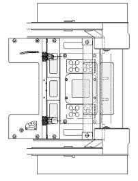
2.3. Safety Warning Label Locations and Descriptions 2.3.1. Label Locations - 121 DD A A 2 14 5 4 15 C C B 6 15 B Always keep safety and information labels clean. If they are lost or damaged, attach them again or replace them with a new label. Safety labels are available in languages other than ENGLISH. Please contact your dealer or DOOSAN if you need non-English labels.
IC0O001I
Label Descriptions
Danger warning for Boom
REMOVING HOSES OR COMPONENT FAILURE
CAN CAUSE LIFT ARMS TO DROP.
USE MECHANICAL LOCK WHEN LEAVING LIFT
ARMS IN RAISED POSITION FOR SERVICE.
FAILURE TO HEED MAY RESULT IN DEATH OR SERIOUS INJURY.
IA0OA11I
Lock Operation2
for canopy
WARNING
BE SURE CANOPY LOCK IS SECURELY LATCHED ANYTIME THE CANOPY IS IN THE RAISED POSION FAILURE TO LOCK CANOPY IN SECURE POSITION MAY RESULT IN INJURY OR DEATH AFTER LOWERING CANOPY MAKE SURE THAT LOCKING BOLTS ARE IN PLACE AND TIGHT
D415547
IA0OA10I
TO ENGAGE BOOM LOCKTO DISENGAGE BOOM LOCK
THE RELEASE LEVER SHOULD REMAIN IN LOCKED POSITION WITH BOOM IN UP AND LOCKED POSITION
HOLD LOCK ARM REMOVE KNOB LOWER LOCK ARM ONTO CYLINDER ENSURE RELEASE LEVER IS IN LOCKED POSITION RAISE BOOM UNTIL LOCK ARM RESTS ON THE CYLINDER ROD LOWER BOOM SLOWLY UNTIL THE LOCK ENGAGES AGAINST TOP CYLINDER
LOCK POSITION
THE RELEASE LEVER SHOULD BE IN THE RELEASE POSITION ONLY WHEN RELEASING THE BOOM LOCK
ROTATE LEVER CLOCKWISE TO RELEASE POSITION RAISE BOOM TO HIGHEST POSITION LOWER BOOM SLOWLY TO LOWEST POSITION LIFT BOOM LOCK ARM, ROTATE LEVER COUNTER-CLOCKWISE MOUNT LOCK ARM IN ORIGINAL POSITION USING KNOB
RELEASE POSITION
D415332
IA0OA12I
2.3.2.
lockWarning
latch31 - 13D415530 D A N G E R
Boom
Warning for engine fan Warning for high temperature muffler ROPS/FOPS Warning for Universal Attachment System7 6 5 4 - 14W A R N I N G D415545 IA0OA08I D415546 HOT EXHUAUST AND MUFFLER WARNING IA0OA09I IC0O047I WARNINGUNLATCHED ALWAYS ASSURE THAT LATCHED ARE FULLY ENGAGED. LATCHED D415534 View "A-A" (Quick Tach) IC0O002I
WEAR SEAT
OPERATE
SUDDEN
SEAT
- 15Warning for general safety rules.Warning for fastening seat belt and seat bar.98 D415532 ALWAYS
BELT. ALWAYS
WITH
BAR IN DOWN POSITION. AVOID
AND ABRUPT MACHINE OPERATION. NEVER CARRY RIDERS. NEVER USE LOADER AS MANLIFT OR WORK PLATFORM. WARNING IA0OA13I WARNING D416620 READ AND UNDERSTAND THE OPERATOR'S MANUAL PRIOR TO OPERATING THIS MACHINE FAILURE TO FOLLOW THESE PRECAUTIONS CAN CAUSE INJURY OR DEATH. CARRY LOAD LOW. AVOID STEEP SLOPES AND HIGH SPEED TURNS. TRAVEL SLOWLY OVER ROUGH TERRAIN. NEVER CARRY MORE THAN RATED OPERATING LOAD. NEVER PLACE ANY PART OF YOUR BODY UNDER BOOM OR ATTACHMENTS. KEEP BOTH FEET ON PEDALS AND BOTH HANDS ON CONTROLS WHILE OPERATING MACHINE. AVOID DEATH OR SERIOUS INJURY IA0OA15I 3 View "B-B" (Inside of Canopy RH) 8 IA0OA04I 9 10 11 (Inside of Canopy. LH) View "C-C" ALWAYS WEAR SEAT BELT. ALWAYS OPERATE WITH SEAT BAR DOWN POSITIONL AVOID SUDDEN AND ABRUPT MACHINE OPERATION. NEVER CARRY RIDERS. NEVER USE LOADER AS MANLIFT OR WORK PLATFORM. WARNING D415535 BEFORE LEAVING SEAT LOWER BOOM OR ATTACHMENTS TO THE GROUND. STOP ENGINE. SET PARKING BRAKE. RAISE THE SEAT BAR. TO EXIT WHILE THE BOOM DANGER IA0OA17I
LEAVING SEAT :
BOOM
THE GROUND.
ENGINE.
ATTACHMENTS
PARKING BRAKE.
THE SEAT BAR.
SURE PEDALS
LOCKED.
EXIT WHILE THE BOOM IS IN
RAISED POSITION, THE BOOM LOCK
BE ENGAGED.
OUTSDE
OPERATION
- 16Danger warning for maintenance. Service Shedule label Anti-Skid surface12 11 10 D415535 BEFORE
LOWER
OR
TO
STOP
SET
RAISE
BE
ARE
TO
A
MUST
(SEE INSTRUCTIONS ON
OF BOOM LOCK OR
MANUAL.) DANGER IA0OA14I GREASE COOLANT HYDRAULIC TANK CHAIN CASE CHAIN CASE D423400 GREASE GREASE IC0O049I 440Plus440Plus 460Plus/460/470Plus 460Plus/460/470Plus HYDRAULIC TANK CHAIN CASE CHAIN CASE COOLANT D423402 GREASE GREASE GREASE IC0O050I ANTI SKID - STEP P/N D422440 ANTI SKID - BOOM P/N D422441 View "E-E"View “D-D”

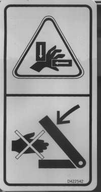

Extinguisher Warning for pinch point Warning for Boom15 14 13 - 17IA0OA76I IC0O058P Left Side IC0O060P IC0O059P Right Side
2.4. General Safety and Hazard Information
2.4.1. Unauthorized Modification
WARNING
UNAUTHORIZED MODIFICATION
•Any modification made without authorization from DOOSAN can create hazards.
•Before making a modification, consult your DOOSAN dealer.
Improper modification could result in injury or death.
•Improper use of safety features could result in serious bodily harm or death.
2.4.2. Clothing and Personal Protective Items
WARNING
CLOTHING AND PERSONALPROTECTIVE ITEMS
•Do not operate or perform system maintenance with loose clothing, jewelry, and loose long hair. They can catch on controls or in moving parts and cause serious injury or death. Also, do not wear oily clothes or wear or have other flammable substances around the equipment.
•Always wear personal protective equipment appropriate for your working conditions, such as a hard hat, safety shoes, hearing protection, mask and gloves.
HA0OA02I
- 18 -
2.4.3. Mounting and Dismounting MOUNTING AND DISMOUNTING
CAUTION
• NEVER jump on or off the machine. NEVER get on or off a moving machine.
•When mounting or dismounting, always face the machine and use the handrails.
•Do not grasp or come in contact with any control levers when getting on or off the machine.
•Ensure safety by always maintaining at least three-point contact of hands and feet with the handrails and steps.
•Always remove any oil or mud from the handrails, steps and shoes.
• NEVER mount or dismount the machine with engine running.
- 19 -
HA0OA03I
2.4.4. Fire Prevention and Hazardous Fluids and Vapors
DANGER
FIRE PREVENTION AND HAZARDOUS FLUIDS AND VAPORS
Fuel, oil, antifreeze, and other flammable fluids and combustibles can be ignited by a flame or hot surfaces. Vapors can be particularly FLAMMABLE and can be HAZARDOUS.
•Keep open flame and hot surfaces away from flammable fluids and combustibles.
•Stop the engine and do not smoke when refueling.
•Tighten all fuel and oil caps securely.
•Refueling and oiling should be done in well ventilated areas.
•Keep oil and fuel in a designated area and do not allow unauthorized persons to enter.
•Thoroughly remove wood chips, leaves, paper and other flammable items accumulated in the engine compartment .
•Check fuel and hydraulic systems for leaks prior to starting or using vehicle.
Have any leaks repaired before operating the machine.
Wipe up any excess oil, fuel or other flammable fluids.
•Be sure a fire extinguisher is present and working and that personnel are properly trained in extinguisher operation.
•Never use ether or other starting aids on any engine with glow plugs or other engine preheating devices.
•See OSHAClass 1910.178.
•Avoid skin contact, injestion and excessive breathing of vapors from fuel, oil, antifreeze, and other fluids.
•See California Proposition 65 in the front of this book.
- 20 -
HA0OA04I
2.5. Operating Safety
2.5.1. Work Site Safety
WARNING
SAFETYAT WORK SITE
Before starting the engine, thoroughly check the area for any unusual conditions that could pose a hazard.
•Before starting the engine, examine the terrain and soil conditions of the work site. Determine the best and safest method of operation.
•If you need to operate on a street, protect pedestrians and cars by designating a person for work site traffic duty and/or by installing fences around the work site.
•Water lines, gas lines, and high-voltage electrical lines (or other objects) may be buried under the work site. Contact each utility and identify their locations. Be careful not to sever or cut any of these lines.
• DOOSAN does not recommend operation of loader in moving water. User should consult a supervisor or safety coordinator anytime water is encountered for any special operating procedures.
- 21 -
IA0OA16S
2.5.2. Operator’s Cab IN OPERATOR’S CAB
WARNING
•Do not leave tools or spare parts lying around in the operator’s compartment. They may damage, break, or interfere with the control levers or switches.
•Keep the cab floor, controls, steps and handrails free of oil, grease, snow, and excess dirt.
•Always check the seat belt, seat bar, and hardware for damage or wear. Replace any worn or damaged parts. Always use seat belts and seat bar when operating your machine.
2.5.3. Safe Operating Practices
WARNING
SAFE OPERATING PRACTICES
•Never use vehicle as a personnel lift.
•Never carry riders, vehicle is designed for single operator only.
•Keep bystanders out of work area.
•Always keep bucket or attachments as low to the ground as possible during all machine operations.
•Loading, unloading, and turning should be performed on flat, level surfaces.
•Never exceed machine’s rated capacity.
- 22 -
2.5.4. Ventilation for Enclosed Areas VENTILATION FOR ENCLOSED AREAS
DANGER
•If it is necessary to start or run the engine within an enclosed area, provide adequate ventilation. Exhaust fumes from the engine can KILL.
2.5.5. Flammable and Explosive Atmospheres
DANGER
FLAMMABLE AND EXPLOSIVE ATMOSPHERES
• NEVER OPERATE ALOADER IN AN AREAWITH AFLAMMABLE/EXPLOSIVE ATMOSPHERE!
•Astandard loader or a loader equipped with a spark arrestor/spark arresting muffler cannot be operated in these areas. Use of these machines in flammable/explosive atmospheres can result in fires and/or explosions which could cause serious injury or death.
•See Code of Federal Regulations (OSHA) 29CFR Part 1910.178, to determine where machines which are approved and labeled as G, GS, D, DS, DY, LP, LPS, G/LP, or GS/LPS are permitted to operate.
- 23 -
HA0OA07I
2.5.6. Precautions for Mirrors, Windows, and Lights
CAUTION
PRECAUTIONS FOR MIRRORS, WINDOWS AND LIGHTS
•Always remove all dirt from the surface of the windows and lights to ensure that you can see well.
•Check that the head lamps and working lamps are installed to match the operating conditions. Check also that they light up properly.
2.5.7. Ensuring visibility
CAUTION
ENSURE GOOD VISIBILITY
•When working in dark places, install working lamps and head lamps, and set up lighting in the work area if necessary.
•Stop operations if the visibility is poor, such as in mist, snow, rain, or other cause, and wait for conditions to improve to a level that allows the operation to be carried out safely.
- 24 -
DANGER
2.5.8. Traveling in Reverse, Sate Working Zone CHECK THAT NO ONE IS NEAR THE MACHINE BEFORE MOVING, TURNING, TRAVELING IN REVERSE OR OPERATING ANYATTACHMENTS
•Always use a signalman in dangerous places or places where the view is not clear.
•Make sure that no one comes inside the turning radius or direction of travel.
•Before starting to move any part of the machine, give a signal to bystanders to remain clear of the machine.
2.5.9. Avoiding High-Voltage Cables AVOID HIGH-VOLTAGE CABLES
DANGER
•Serious injury or death can result from contact with or close proximity to electric lines.
•Keep all parts of the machine or load far away from all electric lines.
- 25 -
IA0OA20I
IA0OA22S
2.5.10. Operating on Snow
CAUTION
OPERATE CAREFULLYON SNOW, ICE, OR WET SURFACES
•When working on snow or icy or wet roads, even a slight slope may cause the machine to slip to the side, so always travel at low speed and avoid sudden starting, stopping, or turning.
•When there has been heavy snow, the road and objects placed beside the road are buried in the snow and cannot be seen, so always carry out snow-clearing operations carefully.
2.5.11. Working on Loose Ground
DANGER
WORKING ON LOOSE GROUND OR UNEVEN SURFACES
•Avoid operating your machine too close to the edge of cliffs, overhangs, loading docks, deep ditches, and other uneven surfaces or drop-offs. If these areas collapse or you get too close to the edge, your machine could fall or tip over and result in serious injury or death. Remember that the soil after heavy rain or blasting is weakened in these areas.
•Earth laid on the ground and the soil near ditches are loose. It can collapse under the weight or vibration of your machine.
- 26 -
2.5.12. Preventing Crushing or Cutting CRUSHING OR CUTTING PREVENTION
DANGER
•Never enter, or put your hand or arm or any other part of your body between movable parts such as between the work equipment and cylinders, or between the machine and work equipment. If the machine or work equipment is operated or moved, the clearance will change and this may lead to serious damage or personal injury.
• ALWAYS keep both feet on pedals and both hands on controls when operating loader.
•The cab structure of the 440Plus, 460Plus/460 complies with the following ROPS (Rollover Protective Structure) and FOPS (Falling Object Protective Structure) criteria. -ROPS per ISO 3471 -FOPS per ISO 3449 Level I
•Never operate without a ROPS/FOPS approved cab.
2.5.13. Parking
DANGER
PARKING MACHINE
•Avoid stopping suddenly. Give yourself ample room when stopping.
•When stopping the machine, select flat hard ground and avoid dangerous places. If it is unavoidably necessary to park the machine on a slope, insert blocks between tires and ground.
As a safety measure, thrust the bucket into the ground.
•If the control lever is touched by accident, the work equipment or the machine may move suddenly, and this may lead to a serious accident.
•Before leaving the operator’s compartment, always fully engage the park brake.
•Lower the bucket horizontally until the bottom touches the ground.
•NEVER exit machine with engine running.
•NEVER leave lift arms raised without boom safety locks being fully engaged.
- 27 -
2.5.14. Precautions for Attachments PRECAUTIONS FOR ATTACHMENTS
WARNING
•When installing/using an optional attachment, read the instruction manual for the attachment and the information related to attachments in the manual.
•Never use attachments that are not authorized by DOOSAN or your DOOSAN dealer. Use of unauthorized attachments could create a safety problem and adversely affect the proper operation and useful life of the machine.
• NEVER attempt to engage or disengage the Universal Attachment System (Quick-tach) levers with the engine running.
2.5.15. Precautions for Loading and Emptying the Bucket
WARNING
•Load, unload and turn on flat level ground. Do not exceed machine rated operating load shown on the rated operating load name plate attached to your machine. Failure to obey warnings can cause the machine to tip or roll over and cause injury or death.
WARNING
•Never dump over an obstruction that can enter the operator cab. The machine could tip forward and cause injury or death.
- 28 -
2.5.16. Precautions for Stopping the engine.
CAUTION
When the engine stops and the seat bar (pedal locking device/parking) is secured in place (lowered). if the pedal is depressed, then the boom or the bucket descends.
CAUTION
When the pedal is kept depressing, then even though the seat bar (pedal locking device/parking) is raised, the boom or the bucket keeps moving regardless of engine’s running or not.
- 29 -
2.6. Maintenance Safety
2.6.1. Periodic Maintenance
WARNING
1. Never attempt to service a machine unless you are authorized and qualified to do so.
2. Before attempting any service on this machine, familiarize yourself with all instructions and warnings in the operators manual and all machine decals.
3. Do not attempt to service machine unless you have the necessary skill, information, safety gear, and tools and equipment to perform the procedure correctly.
4. While service is being performed ensure a warning tag is installed on or near the ignition key switch and clearly visible to prevent inadvertent starting of the machine during service.
5. If a service procedure necessitates running the engine, the control levers must remain in the neutral position and the emergency brake must be fully engaged. Failure to do so can result in injury or death.
6. After completing service check for: proper operation of all controls, correct torque on all fasteners and fittings, any fluid leaks (prior to and after starting engine), all tools and equipment must be removed from the machine.
7. Ensure all hoisting and supporting equipment is in good repair and of adequate capacity to support loader.
8. Failure to follow safety precautions and proper service procedures can lead to machine malfunction or damage, injury to operator or bystanders, or death.
- 30 -
2.6.2. Precautions for High Temperature Operations
WARNING
PRECAUTIONS WHEN HANDLING AT HIGH TEMPERATURES
•Immediately after operations are stopped, the engine coolant, engine oil, and hydraulic oil are at high temperatures, and are still under pressure. Attempting to remove the cap, drain the oil or water, or replace the filters may lead to serious burns. Always wait for the temperature to go down, and follow the specified procedures when carrying out those operations.
•To prevent hot water and oil from spurting out:
1. Turn engine off.
2. Allow water and oil to cool.
3. Slowly loosen cap to relieve pressure before removing.
- 31 -
HA0OA05I
2.6.3. Maintaining and Inspecting Hydraulic Equipment
CAUTION
MAINTAINING AND INSPECTING HYDRAULIC EQUIPMENT
1. Be sure that the machine is parked on level, solid ground when servicing hydraulic equipment.
2.Lower the bucket to the ground and stop the engine.
3.Begin servicing hydraulic equipment only after components, hydraulic oil and lubricant are completely cooled, as they will remain hot and pressurized for a period of time after operation. While servicing heated and pressurized hydraulic equipment, oil may flow off or escape suddenly with a potential of serious injury.
4.Before servicing hydraulic equipment, bleed air from the hydraulic oil tank to release internal pressure.
5.Even after bleeding the air from the hydraulic oil tank, pressure can remain in the various circuits of the hydraulic system. Be sure to operate each control lever a few times to release residual pressure from the system.
6.Avoid inspecting and servicing the travel circuits on slopes, as they are pressurized by gravity even after bleeding the hydraulic oil tank.
7.When connecting hydraulic hoses and tubes, take special care to keep seal surfaces free from dirt and to avoid damaging them.
8.When adding hydraulic oil, always use a recommended manufacturer’s oil. Do not mix oil viscosities. See section 8.2.9, “Fluid Capacities & Specifications’” in the back of this manual.
9.Do not run the engine without oil in the hydraulic oil tank.
• During operation the hydraulic system parts become very hot.
Allow the machine to cool down before beginning inspection or maintenance.
• Keep body and face away from plugs or screws when removing them as they may be pressurized even when cooled.
• The hydraulic oil tank is pressurized. Remove tank cap to release pressure.
10. Whenever possible, all maintenance and lubrication should be done on the machine with the boom lowered to the ground and the engine stopped. Secure boom locks if maintenance is performed with boom raised.
11. Before disconnecting any hydraulic lines, be sure to attach proper labels to the lines to prevent incorrect connections. Always check the machine for proper function after the repair.
- 32 -
2.6.4. Precautions for High Pressure Oil
WARNING
PRECAUTIONS WITH HIGH PRESSURE OIL
•Do not bend high-pressure hoses or hit them with hard objects. Do not use any bent or cracked piping, tubes or hoses. They may burst during use.
•Always repair any loose or broken fuel hoses or oil hoses. If fuel or oil leaks, it may cause a fire.
•Be aware that the machine hydraulic circuits are always under pressure.
•Do not add oil, drain oil, or carry out maintenance or inspection before completely releasing the internal pressure.
•If oil is leaking under high pressure from small holes, it is dangerous if the jet of high-pressure oil hits your skin or enters your eyes. It also can be extremely hot. Always wear safety glasses and appropriate gloves, and use a piece of cardboard or a sheet of wood to check for oil leakage. The stream of oil may not be visible.
•If your skin is punctured by a jet of high-pressure oil, seek a doctor immediately for medical attention.
IA0OA26I
- 33 -
2.6.5. Preventing Battery Hazards
WARNING
BATTERYHAZARD PRECAUTIONS
•Battery electrolyte contains sulfuric acid and can quickly burn the skin and eat holes in clothing. If you spill acid on yourself, immediately flush the area with water.
•Battery acid could cause blindness if splashed into the eyes. If acid gets into eyes, flush them immediately with large quantities of water and see a doctor immediately.
•If you accidentally swallow battery acid, drink a large quantity of water or milk, beaten egg or vegetable oil. Call a doctor or poison prevention immediately.
•When working with batteries, ALWAYS wear safety glasses, goggles, or face shield.
•Batteries generate hydrogen gas. Hydrogen gas is very EXPLOSIVE, and is easily ignited with a small spark or flame.
•Before working with batteries, stop the engine and turn the starting switch to the OFF position.
•Avoid short-circuiting the battery terminals through accidental contact with metallic objects, such as tools, across the terminals or between the hot (+) post and frame or other grounding surface.
•Keep the battery terminals tightened securely. Loose terminals can generate sparks and lead to an explosion.
•When repairing the electrical system or when carrying out electrical welding, remove the negative (-) terminal of the battery to stop the flow of current.
•NEVER attempt to charge or jump start a frozen battery. An explosion may occur.
- 34 -
IA0OA27I
Waste Material Precautions WASTE MATERIALS
CAUTION
•Never dump waste oil
a sewer
put oil drained from your machine
directly on the ground.
Never drain
appropriate state, local, and federal laws and regulations when disposing of harmful liquids, objects, or wastes
solvent, acids, filters, batteries
as oil, fuel,
others.
2.6.7. Rotating Fans and Belts
ROTATING FAN AND BELT
•Keep away from all moving or rotating parts
be careful not to let anything get caught in them.
touch any rotating parts. If your body or tools touch the fan blades or fan belt, they may be cut off or sent flying or it may pull you into the equipment.
- 352.6.6.
in
system, rivers, etc. •Always
in containers.
oil
•Obey
such
coolant,
and
HA0O1043I
and
•Never
DANGER IA0OA28I
2.6.8. Tire Maintenance
Tires should be checked regularly for wear, damage, and proper inflation. When replacing tires, ensure that the size matches those already on the vehicle. Mismatched tire sizes can change vehicle performance and cause
premature wear and damage to drive train components. If tires are replaced in pairs, they should be mounted on the same side of the vehicle to minimize stress on the drive train.
DANGER
Tires should only be mounted/dismounted from rims or repaired by trained and authorized personnel using the proper equipment and procedures. Death or serious injury could result. See OSHA 1910.177.
- 36 -
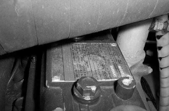
3. SERIALNUMBER LOCATIONS 3.1. Vehicle Serial Number The vehicle serial number plate is riveted on the upper side of mast crossmember. 3.2. Engine Serial Number The engine number tag is riveted on the top of engine valve cover(440Plus). - 37MACHINE TYPESKID-STEER LOADER MACHINE NAME SERIAL NUMBER kW rpm LBS. kg LBS. kg ENGINE POWER OPERATING WEIGHT OPERATING LOAD IA0OA02I IC0O061P 440Plus
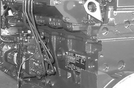
The engine number tag is riveted on the side of engine block(460Plus/460/470Plus). If you need parts, service or information for your engine, you must give the complete engine number to your Cummins distributor. - 38460Plus/460/470Plus IC0O061P
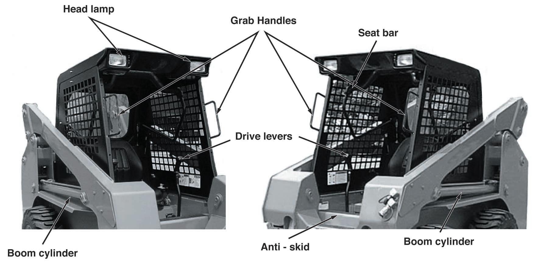
4. MACHINE COMPONENTS
4.1. Identification of Machine Parts
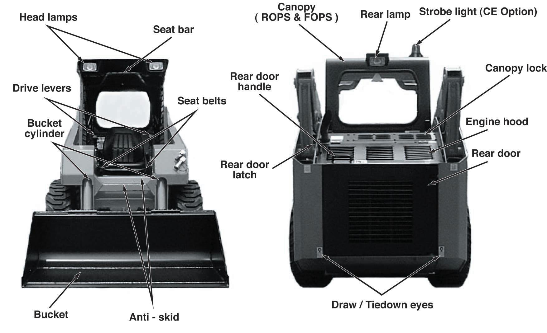
- 39IC0O004P
- 40IC0O005P
INSTRUMENTPANEL-LH
INSTRUMENTPANEL-RH
5. CONTROLS AND INSTRUMENTS 5.1. Instrument Panel 1 78910111213 23456 STOP 1415 IC0O007I
(1)Hour meter (2)Engine oil pressure warning light (3)Alternator indicator light (4)Water temperature warning light (5)HSToil temperature warning light (6)Fuel gage (7)Pre-heat light (8)Diesel engine water in fuel filter indicator light
(9)Warning light (10)HSTpressure warning light (11)Stop light (12)Oil filter warning light (13)Parking brake light (14)Key Switch (15)Light switch - 41IC0O006I
(1) Hour Meter
• Hour meter indicates the total hours of vehicle operating
(4) Water Temperature warning light
• The light turns on when the temperature of the engine cooling water exceeds 110°C (230°F)
(2) Engine oil pressure warning light
• The light turns on when the engine oil pressure is below 0.5kg/cm2 (15 psi).
(5) HST oil temperature warning light
• The light turns on when the temperature of the hydraulic oil to drive HST goes up to 100°C (212°F).
(3) Alternator indicator light
• indicates if the battery charging system is operational. The light will come on when the ignition switch is turned to the ON position.
(6) Fuel Gauge
• Fuel gauge shows the amount of fuel in the fuel tank.
- 42 -
(7) Pre-heat light
• When the key is turned to the “IGN” position and cold weather, the light turns on and preheating of air begins. Light turns off automatically after 5 seconds.
(8) Diesel engine water in fuel filter indicator light
• Indicates when the engine is running, there is water in the fuel filter exceeds 100cc.
(10) HST pressure warning light
• The light turns on when the pressure of the HST pump oil falls down below 5.97 kg/cm2 ( 85 psi )
(11) Stop light
STOP
• The light turns on simultaneously with water temperature and engine oil pressure warning lights.
(12) Oil filter warning light
• If the oil filter becomes clogged, the light turns on.
(9) Warning light
• The light turns on simultaneously with charge, HST oil temperature, HSTpressure and oil filter warning lights.
- 43 -
(13) Parking brake light
• Raising the hand lever, the parking brake is engaged and the light turns on.
(15) Light Switch
• Step 1 : Two front lights turn on.
• Step 2 : Two front lights and on rear light turn on simultaneously.
(14) Key switch
• When the key is turned to the “IGN” position, all the warning lights on the instrument panel come on. And use this position to start in cold weather, when preheating is completed (5 seconds), the pre-heat light turns off.
• When the key is turned to the “ST”position, the engine is started. When the key is released, it will return to the “IGN” position automatically.
- 44 -
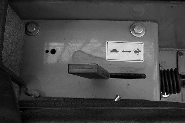
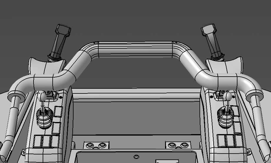
5.2. Controls (1) Drive control lever(RH)(7) Parking Brake (2) Drive control lever(LH)(Released Position) (3) Boom pedal(8) Auxiliary Hydraulic (4) Bucket pedalThumb Control (5) Throttle Lever(9) Horn Button (6) Seat Bar (10) Pressure Relief 5.2.1. Drive control lever() • The steering levers are on the left and right sides in front of the seat. The levers are independent of each other. – FORWARD MOVE : Push both levers forward. – BACKWARD MOVE : Pull both levers backward. – STOP: Hold both levers at neutral position. 21 - 45FASTEN SEAT BELT (3)(2) (10) (6) (7) (4)(8) (9)(1) (5) IA0OA34I FASTEN SEAT BELT (2)(1) IA0OA35I
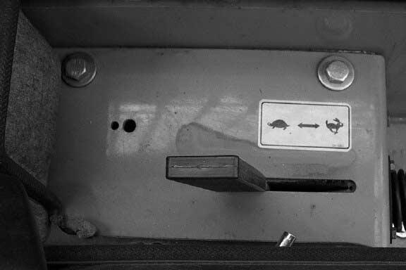
The distance of lever movement
travel speed.
proportional
5.2.3. Boom Pedal
For safety purposes, the operator can start the engine only when both drive levers are in the neutral position.
Pedals
SEAT
Boom pedal controls the lifting and lowering of the boom. The speed is controlled by the degree of the pedal.
NOTE: Press the front part of the pedal fully to the bottom, then the pedal will be locked to floating position, which makes the boom move freely. That is a comfortable function to level the ground. To release the boom from the
is
to
NOTE :
5.2.2.
()
()
3 43 - 46FASTEN
BELT (3)(4) IA0OA36I Boom up Neutral Boom down Floating position IA0OA37I
floating status, press the rear part of the pedal. Float position should only be used with vehicle in reverse. 5.2.4. Bucket Pedal () • This is the pedal to tilt the bucket forward or backward. The speed is controlled both for forward and backward tilting by the degree of the pedal pressing. 5.2.5. Auxiliary Hydraulics Thumb Control (6) When using an attachment other than the standard bucket, follow the instructions for each separate attachment. 4 - 47Backward tilting Backward tilting Neutral Forward tilting Forward tilting IA0OA38I (4) (1)(2)(3) (5) (6) IA0OA39I CAUTION
The Auxiliary Hydraulics Thumb Control
system is activated by pushing the “on” button
(1) on the forward control panel. The green light (2) on the panel will illuminate when the system is active. This system can be operated in two modes by utilizing the rocker switch (4) (5) on control panel.
Momentary control: This system is activated with the rocker switch (5) in the down position. The auxiliary hydraulics will only operate when the thumb button (6) on the drive control handle is depressed.
Detent control: This system is activated with the rocker switch (4) in the down position. The thumb button (6) controls the direction of flow in this mode but it cannot stop or pause flow once the system is activated. Auxiliary hydraulics will remain active until the “off” button (3) on the panel is pushed or the key switch is turned to off.
5.2.6. Engine Control
A
• Throttle lever (A) controls the engine speed.
Push the throttle lever forward to increase the engine rpm and pull backward to decrease the engine rpm.
- 48IC0O008P
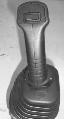
5.2.7. Seat Bar
• The seat bar is installed to help protect the operator.


Raised Position
NOTE: The pedals are locked if the seat bar is in the raised position. Lower the seat bar to operate the pedals.
Lowered Position
NOTE: 440Plus, 460 Plus/460/470Plus are equipped with a seat bar safety interlock that sets the park brake with the seat bar raised.
The seat bar must be lowered for travel.
- 49 -
IA0OA17P
IA0OA18P
- 505.3. Controls (Joystick : Option) Drive Control HandleParking Brake Boom & Bucket HandleThrotlle Lever Auxiliary HydraulicHorn Button Thumb ControlPressure Relief Seat Bar4 8 73 62 51 1 2 3 5 7 4 6 8 IA4O5001
control
handle
handle
engine
- 515.3.1. Drive
lever(Joystick) • The steering handle are on the left sides in front of the seat. – FORWARD MOVE : Push forward. – BACKWARD MOVE : Pull backward. – STOP: Hold
at neutral position. The distance of
movement is proportional to travel speed. NOTE : For safety purposes, the operator can start the
only when drive handle are in the neutral position. 1 1 IA4O5002
5.3.2. Boom & Bucket Handle ()
Boom handle controls the lifting or lowering of the boom, and tilting or dumping Bucket. The speed is controlled by the degree of the handle.
ground. To release the boom from the floating status, pull the boom handle backward. Float position should only be used with vehicle in reverse.
Floating Position
Boom Down
Bucket Dump Bucket Tilt
Boom Up
NOTE: Push the Boom handle fully to the forward, then the handle will be locked to floating position, which makes the boom move freely. That is a comfortable function to level the
- 52 -
2
Auxiliary Hydaulic Thumb Control
The Auxiliary Hydraulics Thumb Control
system is activated by pushing the “on” button (1) on the forward control panel. The green light (2) on the panel will illuminate when the system is active. This system can be operated in two modes by utilizing the rocker switch (4) (5) on control panel.
Momentary control : This system is activated with the rocker switch (5) in the down position. The auxiliary hydraulics will only operate when the thumb button (6) on the drive control handle is depressed.
When using an attachment other than the standard bucket, follow the instructions for each separate attachment.
Detent control : This system is activated with the rocker switch (4) in the down position. The thumb button (6) controls the direction of flow in this mode but it cannot stop or pause flow once the system is activated. Auxiliary hydraulics will remain active until the “off” button (3) on the panel is pushed or the key switch is turned to off.
5.3.3.
CAUTION - 53(4) (1)(2)(3) (5) (6) IA0OA39I
• When auxiliary hydraulic attachment has residual pressure, so you cannot remove attachment from machine, you must reciprocate the knob down to bleed off the attachment
- 54 -
IA0OC10P
•
Engine Control Joystick
Throttle lever (A) controls the engine speed. Push the throttle lever forward to decrease the engine rpm and pull backward to increase the engine rpm.

5.3.4.
IA4O5004 - 55A
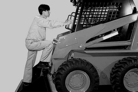

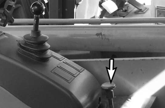
6. OPERATING INSTRUCTIONS 6.1. Inspection Before Boarding Refer to Section 7.3 Pre/Post Start Checks 6.2. Boarding the Loader (1) Use the bucket steps and grip handles to get on and off the loader. (2) Adjust the seat position with the seat adjusting lever. - 56IA0OA41P IA0OA42P IA0OA43P
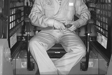
(3) Fasten the seat belt and adjust it snugly across the hips.
(1) Be sure all controls (the foot pedals and drive control levers) are in neutral position.
(2) Set the throttle lever at half-throttle position.
(3) When the key is turned to the “IGN” position, all the warning lights on the instrument panel come on. And use this position to start in cold weather, when preheating is completed (5 seconds), the pre-heat light turns off.

(4) When the key is turned to the “ST”position, the engine is started.
When the key is released, it will return to the “IGN” position automatically.
(4) Lower the seat bar all the way.
6.3. Starting
CAUTION
Refer to section 7.3 for pre-start maintenance checks.
- 57IA0OA18P
A IC0O008P
DANGER
Cold Temperature Starting and Operation
Before any Doosan skid steer loader is operated in cold ambient temperatures (below 45°F), the hydrostatic system needs to be properly warmed up to assure precise drive operation. This is especially crucial due to the fact it has a servo controlled hydrostatic drive system.
To properly warm up the hydraulic system you should: 1. Disconnect any attachment lines from the auxiliary hydraulic couplings. 2. Following all proper procedures as outlined in this manual, start the engine and run at high idle (full throttle position). 3. Set the auxiliary hydraulic pedal in the full operational position. 4. Depending on ambient temperature proper warm up time will vary from 3 to 15 minutes. This procedure should be continued until both A) The outside of the hydraulic tank is warm to the touch and B) Using short slow movements the drive controls react normally to inputs. Caution should be taken during the initial control movements as warm oil may be delayed in reaching the control servos.
- 58 -
6.4. Traveling and Steering
(1) Push the throttle lever forward to raise the engine speed.
(2) Operate the boom and bucket pedals to raise the bucket to 15-20 cm (6-8 in) above the ground.
(3) Push left and right drive control levers simultaneously forward (or pull them backward) to make the vehicle travel forward (or backward).
(4) To stop the vehicle, make the left and right drive control levers return to the neutral position slowly. DOOSAN skid steer loader is designed with drive control levers which return to neutral positions automatically, when the levers are released.
(1) Steering procedure is illustrated as follows:
• Gradual Turning
Push one lever farther forward than the other.
When traveling or steering, always lower the boom to the carry position.
- 59ForwardBackward IA0OA45I Left TurnRight Turn IA0OA46I CAUTION
•Sharp
Turning Push one lever forward and pull another leverbackward. Be alert for tail swing. - 60Left TurnRight Turn IA0OA47I CAUTION
6.5. Traveling and Steering (Joystick : Option)
(1) Pull the throttle lever backward to raise the engine speed.
(2) Operate the boom and bucket handle to raise the bucket to 15-20 cm (6-8 in) above the ground.
(3) Push left drive control handle forward (or pull it backward) to make the vehicle travel forward (or backward).
(4) To stop the vehicle, make the left drive control handle return to the neutral position slowly.
DOOSAN skid steer loader is designed with drive control handle which return to neutral positions automatically, when the levers are released.
(1) Steering procedure is illustrated as follows:
• Gradual Turning
Push left drive handle diagonally forward.
TurnRight
CAUTION
When traveling or steering, always lower the boom to the carry position.
- 61 -
ForwardBackward IA0OA45I Left
Turn IA0OA46I
•Sharp Turning
6.6 Operation
CAUTION
For safe and economical handling with the DOOSAN skid steer loader, the operator must have a thorough knowledge of safety instructions and a good grasp of the construction and performance features of the vehicle. Then he must choose the operating approach best matched to the actual conditions.
(1) Bucket filling
- 62 -
Push left drive handle left side or right side.
Be alert for tail swing. Left TurnRight Turn IA0OA47I IC0O011I CAUTION
CAUTION
When traveling forward into the material, make the bucket parallel to ground.
(3) Bucket dumping
Keep the bucket load level while raising the boom to prevent the load from falling down over the back of the bucket. Raise the bucket high enough and tilt the bucket forward to dump a bucketful of material. When loading a truck, be careful not to contact the bucket or frame with the truck.
(2) Bucket scooping
Move the vehicle forward slowly with the bucket held parallel to the ground or tilted down slightly.
When the bucket is sufficiently full, roll back and raise the bucket simultaneously.
IMPORTANT
Do not shake the bucket unnecessarily to dislodge sticky material. Vibrations put excess stress on the bucket cylinder and stopper, which in turn will reduce machine life.
- 63 -
. IC0O012I IC0O013I
(4) Leveling the ground
Drive forward or backward with the bucket tilted and raised slightly off the ground to perform leveling.
Also, leveling jobs can be performed by using the floating position for the boom according to operating conditions. Make the bucket parallel to the ground as much as possible.
Do not drive forward with the boom in float position.
- 64IC0O014I CAUTION
Traveling on a Slope, Parking

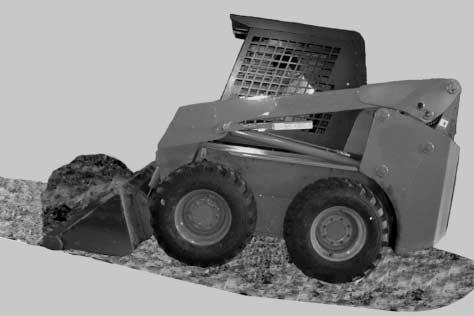
CAUTION
(1) Traveling
(2) Parking
6.7.
on a slope Drive the loader on slopes as illustrated below. (With Full Bucket - forward up and backward down) (With Empty Bucket - forward down and backward up)
• Stop the loader on level ground. • Lower the boom and put the bucket cutting edge on the ground. • Operate your DOOSAN skid-steer loader on level ground as much as possible. • Use caution when operating on slopes. • Keep load as low as possible for maximum stability. - 65IC0O063P IC0O062P
• Pull the throttle lever all the way back.
• Engage the parking brake.
• Turn the key to the “OFF” position.
• Make sure that all controls in operator cabin are in stop position.
• Raise the seat bar all the way up to the roof.
• Disconnect the seat belt.
• Remove the key from the switch.
DANGER
NEVER exit machine with engine running.
6.8. Towing Procedures
NEVER exit machine with boom arms raised unless secured by safety locks.
Towing loaders without following the procedures listed below can result in damage to machine and injury to personnel
(1) Open canopy and secure with safety latches.
(2) Locate bypass/relief valves on each side of HST pumps (refer to illustrations)
RearFront
- 66 -
IA0OA52I
DANGER WARNING
(3) Loosen valves by turning counterclockwise two revolutions.
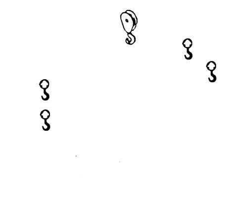
WARNING
Opening of bypass valves will result in a loss of hydrostatic braking capacity. Take precautions to prevent machine movement when opening the valves, and after valves are opened.
6.9. Lifting
(4) Tow loader using the two draw eyes located at lower rear portion of frame.
(5) After towing, tighten valves to 9.5-14 Nm (7-10 ft/lbs.)
Damage to units may result from over-torquing valves.
(6) DOOSAN Skid Steer Loader can draw another machine using the 2 drawing eyes on rear frame. Specified draw bar forces are as follows:
440Plus :2,488Kg (w/ load) 2,100Kg (w/o load)
460Plus/460 :4,199Kg (w/ load)
3,179Kg (w/o load)
470Plus:4,451Kg (w/ load)
3,317Kg (w/o load)
Lifting may shift the load and could result in death or serious injury.
- 67IA0OA53S
WARNING
1. Use proper rated cables and slings for lifting. (min. durable force of cable/sling = 2,500Kgf)
2. Lifting cables should have sufficient length to prevent contact with the machine.
3. Use the 4 holes for lifting i.e. 2 holes in front side frame and 2 holes in inside mast with U-clamp or strap.
6.10. Transportation
15 or less
U - Clamp or Strap
BOOM BOOM
IC0O051I
IA0OA55I
Outside Mast
U - Clamp or Strap Inside Mast
• Use secure, stable, sufficient strength ramps to load (or unload) the machine onto (or from) a transport vehicle and keep the steel ramps inclined 15°or less.
• Follow instructions of the traveling on slopes, while moving on the ramp.
• Lower the bucket to the floor and stop the engine after loading the machine onto a transport vehicle.
• Engage the parking brake.
- 68 -
440 Plus460 Plus/460 470 Plus
frame
holes in lower rear frame.
vehicle
6.11. Bucket and Attachments
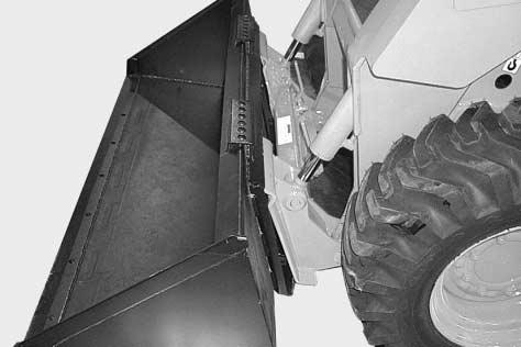
of
of
var-
• Fix the skid loader tightly to the transport truck bed with an approved securing device. The machine has 3 fixing points, i.e.1 holes in front upper
and 2
• Use wheel blocks to prevent
from moving during transportation.
The loader is equipped with a Universal Attachment System (Quick-Tach) in front
the vehicle for rapid replacement
bucket or
ious attachments. (1) Installation <Figure 1> (1) Pull up both handles. (2) Tilt the Quick-Tach forward slightly and drive forward to the bucket until the upper - 69Wire Rope Wire Rope IC0O046I IA0OA57P 460 Plus/460 470 Plus Wire Rope Wire Rope IC0O046I 440 Plus
edge of the Quick-tach is completely inserted to the flange of the bucket.(Figure 1)
backward until the back of bucket becomes perpendicular to ground.(Figure 2)
<Figure 2>
<Figure 3>
(4) Lock the bucket and Quick-tach by pushing down both handles.(Figure 3)

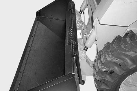
Do not hit the Quick-tach handles when engaging the bucket.
(3) Make sure that the top edge of the Quicktach is inserted and tilt the Quick-tach
- 70IA0OA58P IA0OA59P CAUTION
4>
(5) Make sure that both wedges are inserted firmly through the holes on the bucket (or attachments).(Figure 4)
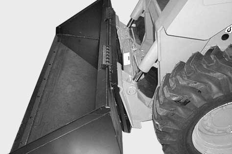
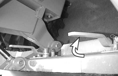
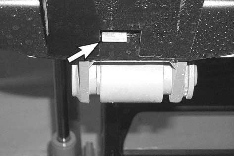
(2) Removal
(1) Lower the boom thoroughly and tilt the bucket down until the bucket cutting edge touches to ground.
(2) Pull out both handles and disengage the locking pin. (Figure 5)
<Figure 5>
(3) Remove the bucket from the machine by driving backward with the Quick-tach tilting down.(Figure 6)
<Figure
<Figure
6> - 71IA0OA60P IA0OA61P IA0OA57P
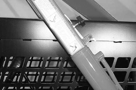
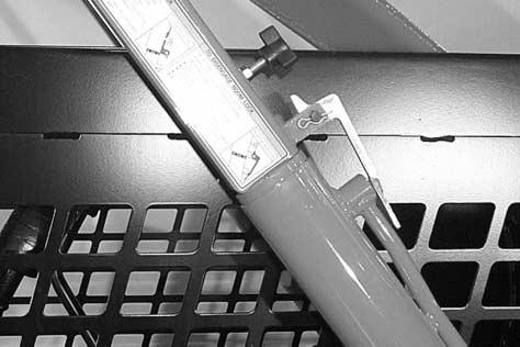
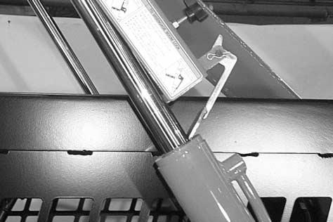
6.12. Boom Lock Operation <Figure 1> <Figure 2> <Figure 3> When working on a machine with the boom up, always engage the boom lock. - 72IA0OA23P IA0OA24P IA0OA25P DANGER
(1) To engage boom lock
Make sure the release lever is secured in the lock position with knob when the boom lock is in use.
(2) To disengage boom lock
The release lever shold be in the release position only when releasing the boom lock.
• With boom fully lowered, hold lock arm and remove knob
• Lower lock arm onto cylinder
• Ensure release lever is in lock position and secured with knob
• Raise boom until lock arm rests on the cylinder rod.
• Lower boom slowly until the lock arm contacts top of cylinder. (Figure 1)
• Rotate lever clockwise to release position (Figure 2)
• Raise boom until lever reaches position as shown in illustration. (Figure 3)
• Lower boom slowly to lowest position
• Lift boom lock arm, rotate lever counterclockwise
• Mount lock arm in original position using knob
IMPORTANT
Do not attempt to lower boom once lock is engaged or cylinder damage will result.
- 73 -
PERIODIC MAINTENANCE
7.1. Safety Warnings
WARNING
1. Never attempt to service a machine unless you are authorized and qualified to do so.
2. Before attempting any service on this machine, familiarize yourself with all instructions and warnings in the operators manual and all machine decals.
3. Do not attempt to service machine unless you have the necessary skill, information, safety gear, and tools and equipment to perform the procedure correctly.
4. While service is being performed ensure a warning tag is installed on or near the ignition key switch and clearly visible to prevent inadvertent starting of the machine during service.
5. If a service procedure necessitates running the engine, the control levers must remain in the neutral position and the emergency brake must be fully engaged. Failure to do so can result in injury or death.
6. After completing service check for: proper operation of all controls, correct torque on all fasteners and fittings, any fluid leaks (prior to and after starting engine), all tools and equipment must be removed from the machine.
7. Ensure all hoisting and supporting equipment is in good repair and of adequate capacity to support loader.
8. Failure to follow safety precautions and proper service procedures can lead to machine malfunction or damage, injury to operator or bystanders, or death.
7.
- 74 -
7.2. Access to Items Requiring Service
IMPORTANT
Daily maintenance checks can be carried out by opening the rear door and engine hood of DOOSAN skid steer loader.
The rear door can be locked by placing a pad lock on the hasp provided on the rear door.
CAUTION
7.2.1. Rear Door and Engine Hood
After pulling the door latch, pull the door handle backward to open the rear door.
ALWAYS keep rear door closed except for service. Confirm that the rear door is closed and the door latch is firmly engaged before operating the loader.
Push the door handle forward to close the rear door.
More service space can be obtained if operator opens up the engine hood after opening the rear door.
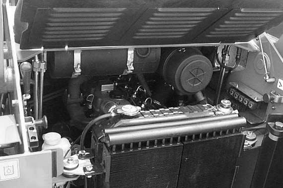
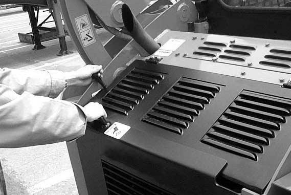
NOTE:
- 75IC0O015P IC0O016P
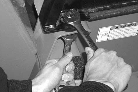
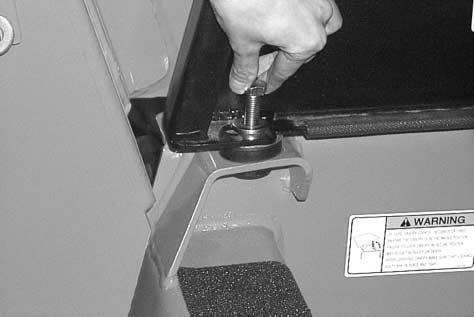
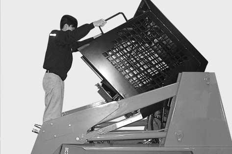
7.2.2. Canopy Tilting • Stop the loader on level ground and lower the boom all the way. • Turn off skid loader • Set park brake • Loosen both mounting bolts at the front corners of the canopy. • Remove attaching hardware • Hold the grip handles on canopy and then liftslowly all the way up. - 76IA0OA64P IA0OA65P IA0OA66P
Canopy Lock
• Hook the rectangular canopy lock to the hook attached on right rear side of the canopy.
• To lower, reverse the above procedure.
7.3. Daily Pre/Post Start Checks
7.3.1. Pre-Start Checks
1. Check engine oil level. Refill if necessary.
2. Check hydraulic oil level. Refill if necessary.
3. Check coolant level. Refill if necessary.
Check the engine fan/alternator belt.
Check the battery and battery cables.
Check the fuel system for leaks.
Check the hydraulic system.
Grease all fittings.
9. Inspect for any loose or missing nuts and bolts
10. Inspect structural members and welds for cracks or deformation.
11. Check the loader tires for proper inflation and unusual wear
12. Check the fuel level.
Never operate without canopy lowered and properly secured.
13. Check the condition and security of the operator seat belt and seat bar.
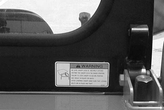
4.
5.
6.
7.
8.
- 77IC0O017P CAUTION
WARNING
If any of the following pre/post start checks indicate that service may be required, have such service performed before using the machine.
7.3.2. After Starting-Before Operation
1. Start the engine and observe the intial exhaust color at start and at normal operating temperatures. Excessively black, blue, or white exhaust is an indication of a problem. Listen for any abnormal sounds.
2. Check the operation of all exterior lights, instrument panel indicator lights and installed optional equipment.
3. Check the operation of all switches.
4. Check the operation of all controls.
Check loader for movement with controls in neutral. Should movement occur refer to service manual for proper adjustment procedure.
a. Check for proper operation of boom, bucket, and accessories ( if attached ).
b. Insure that the boom and bucket pedals are locked with the seat bar raised.
- 78 -
Service Schedule
maintenance
receive
performance
reliability from
SKID STEER LOADER
working conditions.
to follow a
maintenance program can lead to premature wear and component failure. Adverse conditions
excessive dust or corrosive vapors, etc.) may require more frequent service.
Engine Oil
SERVICE SCHEDULE
SERVICE REQUIRED
Check the oil level and fill oil as needed.
Replace the oil.
Replace the oil filter.
System Engine
Cooling System Air
Cleaner
Clean and replace fuel filter element. Priming the fuel system
Check cooling level and add as needed.
for leaks
Check and adjust the tension of fan belt
Check the indicator.
or replace the outer element when the red ring shows.)
Clean the dust cover.
Replace the outer element. (Replace the inner element every third time the outer element is replaced).
time )
7.4.
This
schedule was designed for you to
optimum
and
your
under typical
Failure
scheduled
(e.g.,
- 79 -
HOURS ITEM
everyeveryeveryeveryeveryevery day501002505001000 (First time)(440Plus(460Plus) (First time)(440Plus)(460Plus) (Clean)(Replace) (First time) (Clean)(Replace)
Fuel
Check
(Clean
(Replace First
Nuts
Seat Belt
Seat Bar
Signs
SERVICE SCHEDULE HOURS
REQUIRED
Check air pressure and for damage to tires.
Tighten to correct torque if loose.
Check the condition of seat belt.
Check the seat bar for correct operation.
Check for damaged signs and replace if needed.
Pivots
Grease pivots as needed.
Check the water level and battery cables for corrosion.
whether battery cables are tightly clamped.
covers.
Check the oil level and add as needed.
Hydraulic Oil
Hydraulic Tubes and Hoses
Chain Case Oil
Hydraulic Filter
Spark Arrestorfor Muffler
Suction filter in tank
Air breather cap
Replace the hydraulic Oil.
Check for damage and leaks and replace as needed.
Replace the oil.
Replace the filter.
Clean the spark chamber
Inspect and clean or change
and clean or change
time)
time)
- 80 -
ITEMSERVICE
Tires Wheel
Safety
Battery
Check
Check
Inspect
(First
(First
everyeveryeveryeveryeveryevery day501002505001000
7.5. Lubrication Points - 811 2 3 4 7 8 9 6 5 IC0O018I
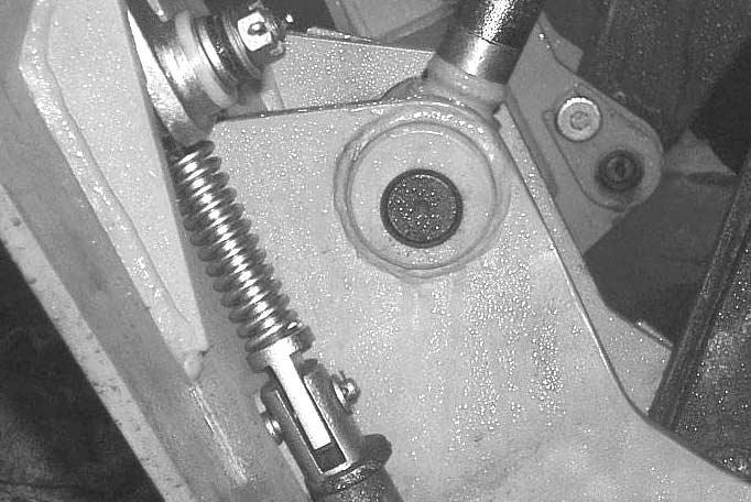
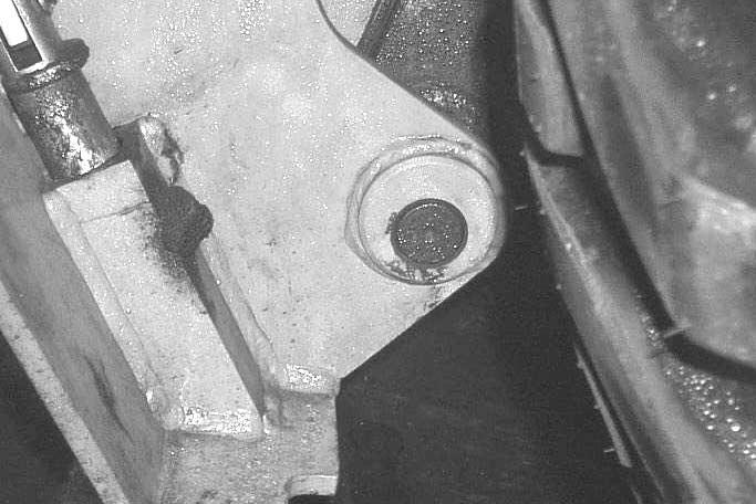
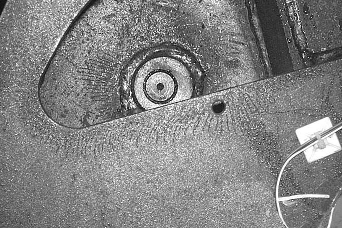
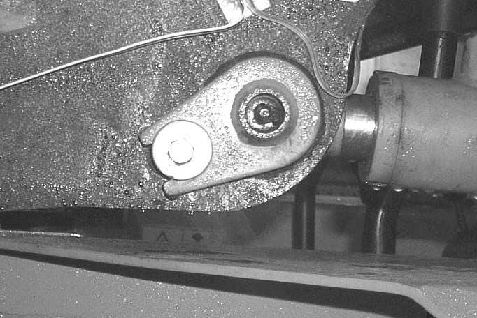
1. Bucket cylinder pivot 2. Lower bucket/boom pivot 3. Upper bucket cylinder pivot 4. Front mast cylinder pivot - 82IC0O019P IC0O020P IC0O021P IC0O022P
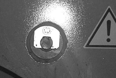
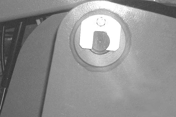
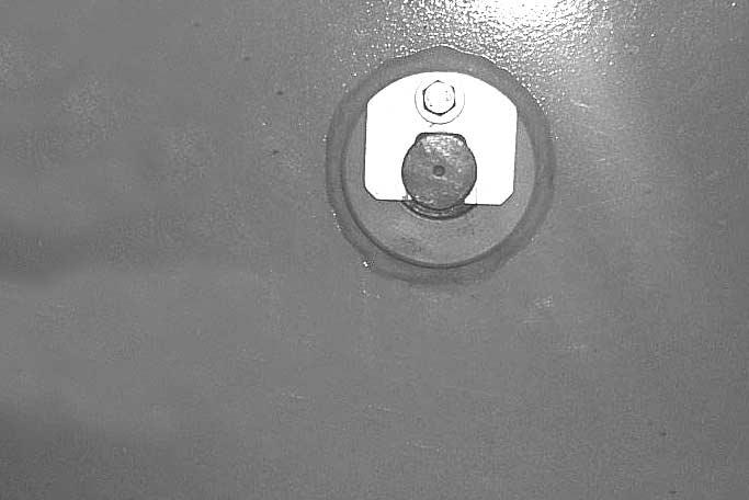
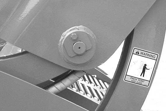
5. Rear mast cylinder pivot 6. Front mast pivot 7. Rear mast pivot 8. Front boom pivot - 83IC0O052P IC0O024P IC0O025P IC0O026P
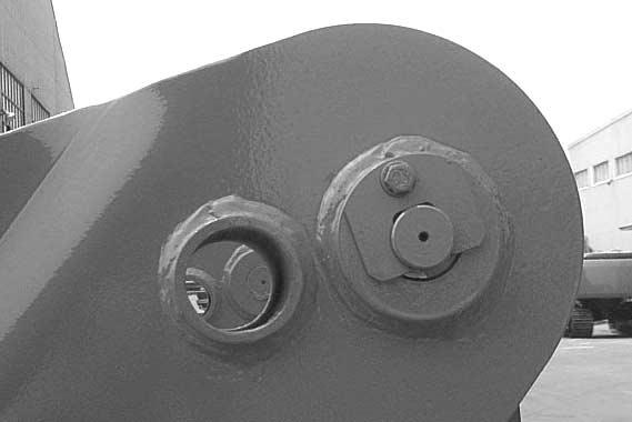
9. Rear boom pivot - 84IC0O028P
FASTEN SEAT BELT
- 85 -
10 10 IA0OA75I
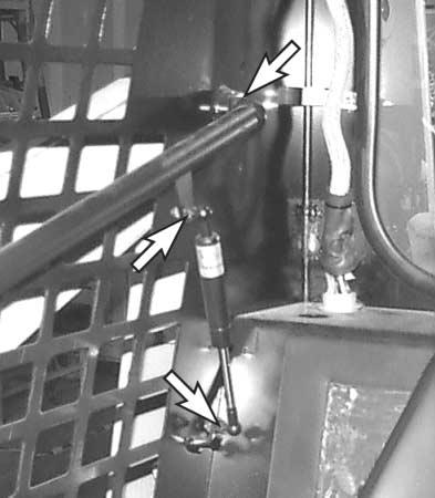
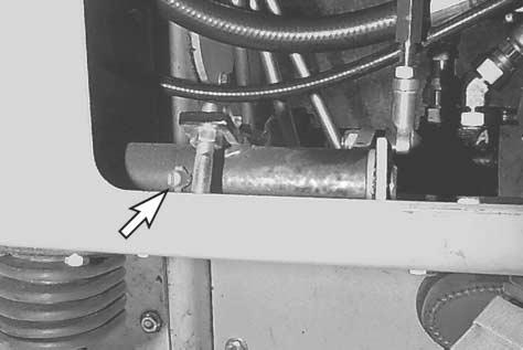
10. Drive control lever fitting NOTE: Cab must be opened to access. 7.6. Operator Restraint Lubrication and Maintenance 1. Seat bar mounting points - 86IA0OA78P IA0OA77P
7.6.1. Lubrication
All seat bar mounting points (right shown-left in mirror position) should be checked for security, cleaned of any dirt and debris, and lubricated daily. Use either a spray lubricant or a light machine oil at the points marked on the illustration. Lubrication for the pedal lock linkage is covered in the previous section (7.5).
7.6.2. Function
Sit in seat and fasten seat belt. Check the seat belt for security at mounting points. With the seat bar up, check for full engagement of the pedal locks (right and left) into the corresponding slots under the pedal assembly. Lower the seat bar. Pedal lock assemblies should fully disengage from pedals.
- 87 -
Engine Lubrication
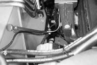
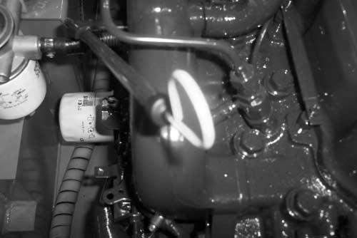
7.7.
7.7.1. General 440Plus - Dipstick 460Plus/460/470Plus - Dipstick - 88IC0O032P IC0O032P Engine oil level should be checked daily. After draining oil and changing filter approximate refill amounts is 2.1gallon(8 liter) for the 440Plus, 460Plus/460/470Plus. Run loader briefly and check oil level on dipstick before returning the loader to service. See section 8.2.10 for fluid recommendations.
Draining Engine Oil
Remove the four bolts from the access plate located on the left bottom corner of the chassis. Remove the drain plug by either reaching through the opening between the radiator and the chassis or through the access plate. Drain oil into an approved waste oil receptacle. Inspect drain plug gasket and if serviceable, replace drain plug. If gasket is deformed or torn, replace gasket and re-install drain plug. Discard oil in accordance with local environmental rules and regulations.
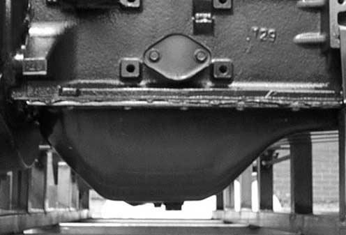
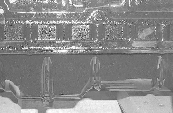
- 897.7.2.
. 440Plus 460Plus/460 470Plus
Remove/ Replace Engine Oil Filter
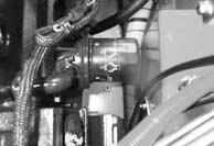
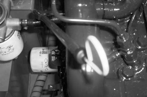
Raise and secure operators cab. Filter is located on left side of engine block.
a strap type or other style filter wrench,
the engine oil filter. Before installing new filter, coat the rubber gasket on the filter with clean oil.
filter BYHAND and tighten until gasket
contacts the mounting surface.
1/2 to 3/4 of a turn, by hand only.
7.7.3.
Using
remove
Install
fully
Tighten
- 90440Plus 460Plus/460 470Plus IC0O031P
7.8. Engine Cooling System
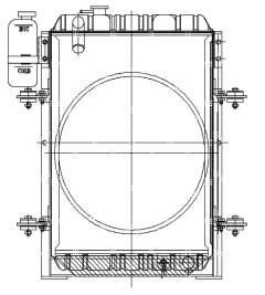
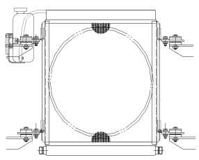
NOTE: Check the cooling water level while the engine is cold.
Accurate coolant level check is not guaranteed when engine is hot, because a hot radiator can flow coolant to sub-tank. Check the coolant level on the sub-tank. Remove the top cap of the sub-tank and fill to the “HOT” mark if coolant level is below “COLD” mark on sub-tank.
tubing to the nipple on the petcock to allow fluid to drain outside of the chassis. Collect the fluid and discard it in accordance with local/federal environmental rules and regulations.
Steam or hot liquid may spurt out if the radiator cap is removed soon after the engine is stopped.
radiator
When removing the radiator cap, turn your face away from cap and cover the cap with a cloth. Turn the cap slowly to release the pressure inside the radiator.
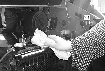
- 91 -
NOTE: The
drain petcock is located on the right radiator tank. Attach a section of 5/16”
(1)
(2)
IC0O033P CAUTION 440Plus 460Plus/460 470Plus
7.9. Fan Belt
7.9.1. Belt Tension
Properly adjusted, the belt should have approximately 3/8” (10 mm) of free play when checked by pressing(thumb pressure 45N) firmly on the belt between the fan and alternator pulleys.
7.9.2. Adjustment
Belt tension can be adjusted by loosening the upper and lower pivot bolts on the alternator.
Use a small pry bar to move the alternator to achieve proper tension and retighten pivot bolts.
- 92IA0OA84S IA0OA85S
Two Stage Air Filter
7.10.1. Removal-Primary Element
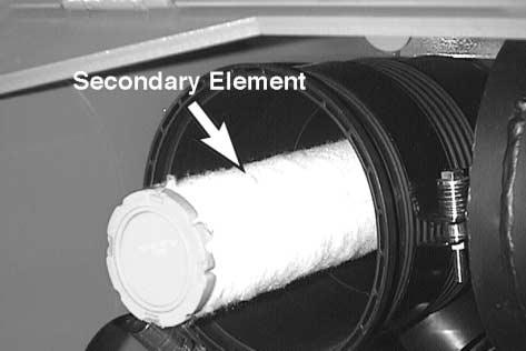
Every day or when the red ring shows on the air cleaner indicator, the primary air cleaner element should be removed and cleaned. Access to the air cleaner assembly is gained through the rear service door. Loosen the canister cover wing nut and remove the cover and gasket. Loosen the cover latches and remove the cover. Rotate the element slightly to separate it from its base and remove it from the air cleaner housing. This element can be cleaned up to six times using compressed air and should be replaced every 500 operating hours.

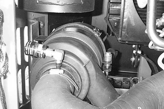
7.10.
- 93IC0O034P IA0OA86P IA0OA87P
7.10.2. Removal-Secondary Element
Unlike the primary element, the secondary element is designed for replacement only and is not to be cleaned. The secondary element is nested inside the primary element and can be removed easily once the primary element is out of the vehicle. The secondary element should be replaced at least with every third change of the primary element.
7.10.3. Installation
Installation is simply the reverse of the above procedures. Ensure that the element and gasket are not damaged during replacement. The air cleaner will not function properly if the gaskets do not seat completely.
7.11. Spark Arrestor
7.11.1. General
This vehicle is equipped with a U.S.D.A. Forestry Service approved spark arrestor muffler. To keep it in working condition, the spark chamber must be emptied every 100 hours of operation.
IMPORTANT
Extreme operating
conditions may greatly accelerate the need to clean or replace these elements.
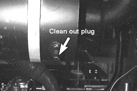
- 94 -
IA0OA89P
7.11.2. Maintenance
The engine must be completely cool before attempting to clean the spark chamber. NEVER attempt to empty the spark chamber on a hot engine. Raise and support the loader and open and secure the operators cab. Remove the clean out plug from the spark chamber. Ensure that the individuals performing this operation are wearing safety glasses with side shields. Start the engine and run for approximately 10 seconds while the second individual wearing protective gloves holds a piece of wood over the exhaust outlet. Re-install plug and lower and secure cab.
7.12. Battery
7.12.1. Remove and Install
Removal: The battery is located in the left center side of the chassis. Access to battery is gained through the opened canopy. Disconnect the negative (-) battery cable first, then disconnect the positive (+) cable. Remove the wing nuts from the battery hold down clamp, and remove the clamp assembly. Remove the battery from the loader.
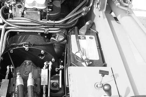
- 95IC0O035P
Installation: Installation procedure is the reverse of the removal procedure. Before beginning installation, clean the battery terminals and cable ends with a wire brush. Be sure to connect the negative (-) cable last to minimize the potential for sparking. Coat the terminals and cable ends with grease to prevent corrosion.
Next, connect from the negative (-) terminal on the jumper battery to the negative (-) terminal on the loader frame. Once loader has started, remove the ground cable from the frame first.
NOTE: Ensure the jumper battery being used is a 12 volt battery or electrical system damage will result.
7.12.2. Jump Starting the Loader
(See caution pg. 34-frozen battery)
Never attempt to jump start a loader by yourself. There must be one person in the operators seat and one person to connect and disconnect the jumper cables. Before beginning to connect jumper cables, ensure that the ignition switch is in the off position, controls are in neutral and parking brake in fully engaged. Connect from the positive (+) terminal from the jumper battery to the positive (+) terminal on the loader battery.
- 96 -
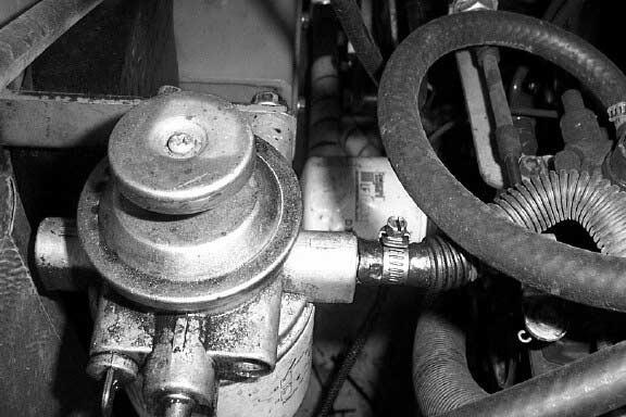
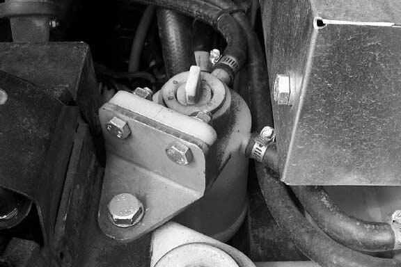

7.13. Fuel System/Filters • 440 Plus • 460 Plus/460 470Plus - 97IC0O053P IC0O054PFuel filter Fuel filter & Water Separator Water Separator
7.13.1. Removal/Installation-Fuel Filter, Water separator
FUELFILTER : Access to the 440Plus ( 460Plus/460, 470Plus) fuel filter is through the rear service door. The filter is located inside the rear door on the left ( right ) hand side for the 440Plus.(460Plus/460, 470Plus). The filter can be removed with a standard filter wrench. This filter cannot be cleaned or reused. Before installation, coat the rubber gasket on the filter with baseline or light machine oil. Tighten filter until point of complete gasket contact, then tighten another 1/2 to 3/4 turn to completely seal. The 440Plus, 460Plus/460, 470Plus are self-priming, no procedure is necessary.
WATER SEPARATOR: The water separator is located inside the rear door on the right ( left ) hand side for the 440Plus ( 460Plus/460, 470Plus ). The water separator acts as a water trap to separate the water from the diesel fuel. If the engine fails to start or there is a loss of power, it may have to be drained. Remove plug at the bottom of the separator bowl and allow the water to drain. NEVER use gasoline to clean filter. Align the filter bowl and tighten the retaining ring by hand until snug. Finish tightening using the spanner wrench. When complete, refer to section 7.14 for fuel system priming.
- 98 -
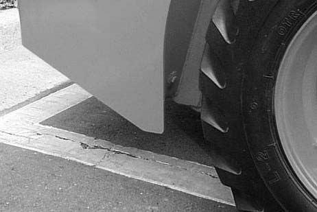

7.13.2. Fuel Tank Drain - 99440Plus 460Plus/460 470Plus The fuel tank drain plug is located directly behind the 440Plus ( right ), 460Plus/460, 470Plus ( left ) rear tire on the chassis. Fuel drained should be disposed of into an approved waste oil container. Discard the fuel in accordance with local/federal environmental rules and regulations. IC0O038P IC0O039P
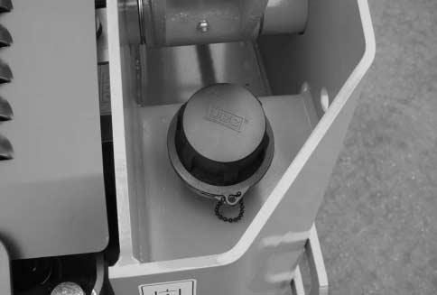

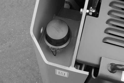

- 100460(Plus), 470Plus OILCAP 460(Plus), 470Plus FUELCAP FUELFILLER 440Plus OILCAP 440Plus FUELCAP
7.14. Priming the Fuel System
7.14.1. Breeding the Fuel System
If air enters the fuel system, it must be eliminated before the engine can be started.
Air can enter the system if:
• The fuel tank is drained during normal operation.
• The low-pressure fuel pipes are disconnected.
• Apart of the low-pressure fuel system leaks during engine operation.
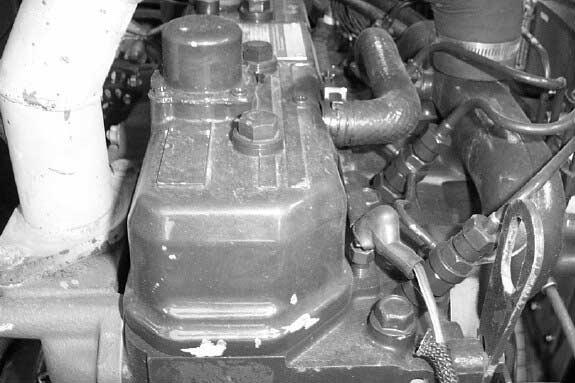
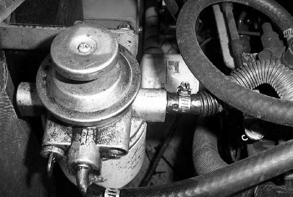
In order to eliminate air from the fuel system, proceed as follows:
• 440 Plus
- 101 -
• 460 Plus/460, 470 Plus
1. Loosen the clamp on the side of the fuel injection pump.
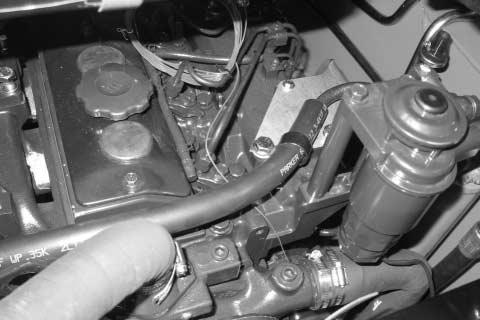
2. Operate the priming lever of the fuel lift pump until fuel, free from air, comes from the vent point. Tighten the vent plug.
3. Turn the start key on the “ON” position.
4. Operate the starter motor for intervals of 15 seconds until the engine starts. If the engine runs correctly for a short time and then stops or runs roughly, check for air in the fuel system. If there is air in the fuel system, there is probably a leakage in the low pressure system. Stop the engine and turn the start key to the “OFF” position.
- 102 -
WATER SEPARATOR: The water separator is located inside the rear door on the left hand side. Removal, cleaning and installation are identical to the procedure for the fuel filter.
Turn the wing nut counter clockwise to open the drain valve on the bottom of the fuel filter.
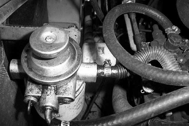
Drain some fuel (and any water) until clean fuel flows from the filter.
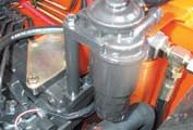
- 1037.14.2. Draining the Water (1) 440 Plus
(2) 460 Plus/460, 470 Plus 1.
2.
IA0OC25P IA4O7025
7.14.3. Cleaning Fuel Strainer
[460 Plus / 460, 470 Plus Only]
At every Engine oil exchange, clean the strainer of fuel feed pump

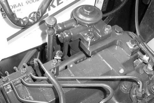
Fuel passes through fuel strainer from fuel tank to fuel filter.
The first filtering device uses the mesh strain er and the second one uses the paper ele ment.
Periodically the mesh strainer must be cleaned and the paper element must be replaced.
Disassembly and cleaning of fuel filter.
1. Loosen the bolts and separate the mesh strainer.
2. Pull out the mesh strainer.
- 104 -
3. Soak the mesh strainer in diesel oil and wipe the outside with a non-metallic brush.
4. Soak the mesh strainer again in new dieseloil and take it out.
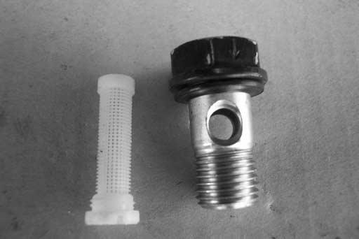
5. Blowing the compressed air inside the mesh strainer.
6. Repeat items 3 through 5, 4-5 times.
7. Assemble in the reverse order of disas sembly.
- 105 -
7.15. Hydraulic System Maintenance

Oil Level Indicator
The hydraulic oil level indicator and filler neck are located on the 440Plus( left ), 460Plus/460, 470Plus( right ) hand side of the loader inside the rear service door. To daily check the fluid level, the loader should be on level ground with the boom completely lowered and the Quick-tach assembly tilted back. The fluid level as indicated on the sight gauge should read between the two red lines.
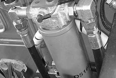
to specifications section 8.2.9 for complete information on fluid capacities and requirements.
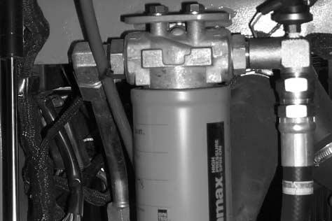
HYDRAULIC
7.15.1.
Refer
- 106 -
FILTER IA0OA95P OILLEVELINDICATOR IC0O055P 440Plus IC0O056P 460Plus/460 470Plus
Filter Replacement
• Replace the filter accordiy to service schedule(7.4)
• The filter should be changed whenever the fluid is changed or whenever the filter indicator shows that it is necessary to change the filter(a red warning lamp on the instrument pannel is lit)
REMOVAL
Access to the 440Plus, 460Plus/460, 470Plus filter are through the rear service door. Remove the filter by turning counterclockwise. Drain the hydraulic oil into an approved waste oil container. While draining, check fluid and filter base for signs of particle contaminants.
INSTALLATION
Before installation you must coat the rubber seal on the new filter with a light coat of hydraulic oil. Spin on filter by hand turning clockwise until the rubber filter seal makes complete contact with the filter head assembly. At this point, turn the filter an additional 3/4 turn to fully tighten. When complete, run the loader and check the hydraulic oil level indicator. Add fluid as needed. Discard the used filter in accordance with local/federal environmental rules and regulations.
7.15.2.
- 107 -
Hydraulic Fluid Replacement
TO REPLACE THE FLUID
The hydraulic tank drain plug is located directly behind the 440Plus ( left ), 460Plus/460, 470Plus ( right ) rear tire on the chassis. Before draining, the loader should be on level ground with the boom completely lowered and the Quick-tach tilted back. Once the loader is drained, oil should be disposed of into an approved waste oil container in accordance with local/federal rules and regulations.
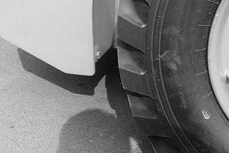

INTERVALOF REPLACEMENT
the fluid according to service schedule(7.4)
may be nessary to change more frequently then the normal interual if the fluid becomes with foreigu material(dirt, water, grease, etc) or if the fluid has beer subjected to temperature levels greater than the maximum recommeded.
7.15.3.
•Replace
•It
- 108IC0O042P 440Plus IC0O043P 460Plus/460 470Plus
Chain Case Drain and Refill
drain
TO DRAIN CHAIN CASE:
drain plugs and drain case oil into
approved waste oil container.
TO REFILLCHAIN CASE:
and tighten case drain plugs.
cab and secure with safety latches.

covers
side shown-right in mirror position
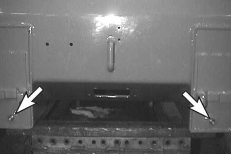
chain case filter necks.
fluid is
440Plus
gal/side, 460Plus/460,
1.85 gal/side or until level is within
inspection cover plug.
and tighten inspection cover.
and secure cab.
- 1097.16.
1. Chain case
plugs 2. Fill cover
1) Remove
an
1) Re-install
2) Open
3) Remove
( left
) 4) Locate
NOTE: Recommended
DEXRON lll 5) Refill is
: 1.7
470Plus :
1/2” of
6) Replace
7) Close
IC0O057P IA0OB00P
7.17. Parking Brake Adjustment
Should adjustment be required begin by opening the cab and securing with safety latches. Locate the park brake handle linkage and return spring.
Remove the spring (A) to release tension from the parking brake linkage.
Loosen the jam nut (B), remove bolt (C), and rotate the clevis on the linkage to adjust the cable tension until parking brake engages fully and interlock functions properly.
Re-attach clevis, re-tighten jam nut and re-connect spring when completed with the adjustment procedure. Inability to achieve proper adjustment using this procedure is indicative of more serious problem and should be referred to your DOOSAN dealer.

- 110IA0OB02P
7.18. Tire Maintenance
7.18.1. General Information
Tires should be checked regularly for wear, damage, and proper inflation. When replacing tires, ensure that the size matches those already on the vehicle. Mismatched tire sizes can change vehicle performance and cause premature wear and damage to drive train components. If tires are replaced in pairs, they should be mounted on the same side of the vehicle to minimize stress on the drive train.
7.18.2. Inflation Pressures
440Plus - 57 psi ( 4.0 kg/cm2 ) 460Plus/460, 470Plus - 50 psi ( 3.5 kg/cm2 )
Tires should only be mounted/dismounted from rims or repaired by trained and authorized personnel using the proper equipment and procedures. Death or serious injury could result.
OSHA1910.177.
7.18.3. Installation and Removal
REMOVAL: Support the frame so that the tire(s) to be removed are off the ground. Insert a wedge under the tire to prevent rotation while the lug nuts are being removed. Remove tire and rim assembly.
INSTALLATION: Install the tire and rim assembly on the axle. Tighten lug nuts to seat rim against axle assembly. Insert a wedge under the tire to prevent rotation while torquing lug nuts. Torque lug nuts to 102-112 ft/lbs (138152Nm) in the pattern illustrated above. Recheck torque after 10 hours of operation.
See
- 1111 3 5 7 2 4 8 6 IA0OB03I DANGER
8. DIMENSIONAL& PERFORMANCE SPECIFICATIONS
8.1. Dimensional Specifications
UnitItem
440Plus
Spec.
460Plus
460
470Plus
• Overall Height
A.Fully Raisedin(mm)
B.To Hinge Pinin(mm)
C.To Canopyin(mm)
• Overall Length
D.With Bucketin(mm)
E.Less Bucketin(mm)
• Overall Width
F.With Bucketin(mm)
G.Less Bucketin(mm)
• Others
H.Wheel Basein(mm)
I.Height of S.I.P.in(mm)
J.Ground Clearancein(mm)
T.Treadin(mm)
U.Departure Angledeg
145.8 (3704) 114.8 (2915) 76.9 (1954) 126.3 (3208) 99.3 (2521) 63.4 (1611) 58.5 (1486) 42.3 (1074.8) 35.8 (908.5) 7.5 (190) 48.1 (1222)
156.3 (3972) 122.3 (3106) 80.1 (2035) 127.9 (3248) 100.7(2557)
70 (1778) 65.4 (1662) 41.8 (1061) 40.9 (1040) 8.6 (218) 53.1 (1350)
- 112 -
26
27
R Q F S A M B L C I UJN H E D K O P IC0O045I
Dumping
K.Dump Angle L.Dump Height
Reach
M.Fully Raised
Rollback
N.Max. at Ground O.Max. Fully Raised
Digging P.Digging Depth
Clearance (Circle)
Q.Front, Less Bucket R.Front, With Bucket S.Rear
deg in(mm) in(mm) deg deg in(mm) in(mm) in(mm) in(mm)
(2224) 25.4 (645)
95.4 (2424) 29.0 (737)
94 0.6 (16) 51.3 (1304) 74.8 (1901) 63.3 (1607)
94 0.4 (10) 46.6 (1185) 76.3 (1939) 62.2 (1580)
•
•
•
•
•
45 87.6
25
440Plus UnitItem 460Plus 460 470Plus 40
26
Spec.
- 113R Q F S A M B L C I UJN H E D K O P IC0O045I
Definitions: (DOOSAN Skid Steer Loader)
Refer to sketches on pages 98 or 99 of this section.
Overall Operating Height (A) - Fully Raised - The vertical distance in inches (millimeters) from the ground to the highest point attainable.
Height to Hinge Pin (B) - Fully Raised - The vertical distance in inches (millimeters) from the ground to the centerline of the bucket hinge pin.
Overall Height (C) - The vertical distance in inches (millimeters) from the ground to the highest point on the unit with the bucket on the ground.
Overall Length (D) - The horizontal distance in inches (millimeters) with the bucket on the ground and level, measured from the foremost point of the bucket cutting edge to the rear most point of the machine.
Overall Length (E) - Without Bucket - The horizontal distance in inches (millimeters) from the furthest rearward to the furthest point forward.
Bucket Width (F) - The maximum outside width in inches (millimeters) of the bucket specified.
Overall Width (G) - The maximum outside width in inches (millimeters) of the machine specified exclusive of bucket.
Wheelbase (H) - The vertical distance in inches (millimeters) from the center of the front wheel or idler to the center of the rear wheel or sprocket.
Height to S.I.P. (I) - The vertical distance in inches (millimeters) from the ground to the Seat Index Point.
Ground Clearance (J) - The minimum vertical distance in inches (millimeters) from the ground to the lowest point on the machine between the tires or tracks with the lift arm raised.
Dump Angle (K) - The maximum angle in degrees that the longest flat section of the inside bottom of the bucket will rotate below horizontal with the bucket hinge pin at maximum height.
Dump Height (L) - The vertical distance in inches (millimeters) from the ground to the lowest point of the cutting
- 114 -
edge with the bucket hinge pin at maximum height and the bucket at a 45°dump angle. The angle is less than 45°, specify angle.
Reach (M) at Maximum Height - The horizontal distance in inches (millimeters) from the foremost point on the machine (including tires, tracks, or loader frame) to the front most point on the bucket cutting edge at a 45°angle with the bucket hinge pin at maximum height. Specify angles less than 45°.
Maximum Rollback (N) - at Ground - Maximum rollback angle in degrees without movement of the lift arm.
Maximum Rollback (O) - Fully Raised - The angle in degrees from the bucket cutting edge level position to the maximum rollback position.
Digging Depth (P) - The vertical distance in inches (millimeters) from the ground to the bottom of the bucket cutting edge at the lowest position with the bucket cutting edge horizontal.
Loader Clearance Circle (Q) - Front No Attachment - The smallest diameter measured in inches (millimeters) that the outermost front point on the machine will describe measured from a point located at 1/2 the wheelbase (H) and 1/2 the overall width (G) of the machine.
Loader Clearance Circle (R) - Front with Standard Attachment - The smallest diameter measured in inches (millimeters) that the outermost front point on the machine will describe measured from a point located at 1/2 the wheelbase (H) and 1/2 the overall width (G) of the machine.
Loader Clearance Circle (S) - Rear - The smallest diameter measured in inches (millimeters) that the outermost rear point on the machine will describe measured from a point located at 1/2 the wheelbase (H) and 1/2 the overall width (G) of the machine.
Tread or Track Gauge (T) - The transverse distance in inches (millimeters) between the centerlines of the tires or sprockets. If the front and rear are different, both must be specified.
Angle of Departure (U) - The angle in degrees taken from a line drawn from the lowest and rear most portion of the rear overhang to the rear bottom face of the rear tire to the ground.
- 115 -
Operational Specification
8.2.1. Performance
Spec.UnitItem
• Rated Capacity
Bucket Capacity
Operating Weight
Tipping Load
Hydraulic Lifting Capacity
Break Out Force- Bucket - Boom
• Raising Time- W/OLoad - W/ Load
• Lower Time- W/O Load - W/ Load
• Boom • Dump Time- W/O Load - W/ Load
Rollback Time- W/OLoad - W/ Load
• Drawbar Pull- W/OLoad - W/ Load
Travel Speed
Forward
• Reverse
lb(kg) ft3(m3) lb(kg) lb(kg) lb(kg) lb(kg) lb(kg) sec sec sec sec sec sec sec sec lb(kg) lb(kg) mph(km/h) mph(km/h)
1850(839)
11.9 (0.34)
5985(2715)
3946 (1790) 4465 (2025) 2910 (1320) 3285 (1490)
4.7 4.7 4.1 3.5 1.9 1.9 1.6 1.7
4923 (2233) 5908 (2680)
7.3 (11.8)
7.3 (11.8)
2250(1020)/2000(907)
14.1 (0.40)
7174(3254)/7119(3229)
4497(2040)/4339(1968)
4718(2140)
4678 (2122) 5194 (2356) 4.4 4.5 4.5 3.8 2.6 2.5 2.1 2.5
5256 (2384)/5068(2299)
5772 (2618)/5800(2631)
7.64 (12.3)
7.64 (12.3)
2500(1134)
14.1 (0.40)
7478(3392) 5000(2268)
4718(2140)
4678 (2122)
5194 (2356) 4.4 4.5 4.5 3.8 2.6 2.5 2.1 2.5 5256 (2384)
5772(2618)
7.64 (12.3)
7.64 (12.3)
8.2.
(Per SAE J732 Feb 80)
- 116 -
•
•
•
•
•
•
•
•
440Plus460Plus/460470Plus
8.2.2. Power Unit
Spec.UnitItem
Cummins
Cummins
Cummins
in3(cc) in(mm) in(mm) hp(ps)/rpm rpm rpm ft.lb(kg.m)/rpm
A2300 Diesel Water 4 139.7 (2290) 3.46 (88) 3.70 (94) 48.3 (49)/2600 2810±50 900±25 110.7 (15.3) 1600 3.0 Full Flow
B3.3 Diesel Water 4 198.9 (3260) 3.74 (95) 4.52 (115) 65/2600 2800±50 970±30 157.7 (21.8) 1600 20 Full Flow
B3.3T
Diesel Water 4 198.9 (3260) 3.74 (95) 4.52 (115) 75/2600 2800±50 970±30 193.1 (26.7) 1600 27.2 Full Flow
- 117• Make • Model • Type of Fuel • Cooling Medium • No. of Cylinders • Displacement • Bore Size • Stroke • Horsepower Net • High Idle • Low Idle • Torque • Torque Rise • Lubrication-ea
% -
440Plus460Plus/460
470Plus
- 1188.2.3. Final Drive Components • Chain • No. of Teeth • Drive Sprocket (Motor) • Counter Sprocket • Drive Sprocket (Axle) • Ratio • Tire • Type • Size • Pressure • Wheel • Size • Hole x Pitch Circle Diameterea ea ea psi (kg/cm2)2 Chain with Super80HT& Super80HT 12 32 2.67 FlotationTubeless 10-16.5, 8PR 57 (4.0) 8.25 X 16.5 8 X 8” Spec.UnitItem 2 Chain with RS100HT& RS100HT 10 28 2.8 FlotationTubeless 12-16.5, 8PR 50 (3.5) 9.75 X 16.5 8 X 8” 440Plus460Plus/460/470Plus
Hydrostatic Transmission Pump
Spec.UnitItem
440Plus460Plus/460
Type
Max. Displacement
Relief Setting Pressure
Internal Charge Pump
Rotation
Swash Plate Operating Angle
Mounting
Shaft
Standard Pump
Flow (Max)
Relief Pressure (max) at charge pump
High Flow Option Pump
Flow (max)
Relief Pressure (max) at charge pump
in3(cc)/rev
kg/cm2(psi)deg -
Piston, Variable Displacement (Manual)
2.68 (44) 250 (3555) None clockwise ±16
Piston, Variable Displacement (Manual)
2.65 (43.5) 250 (3555) None clockwise ±16
470Plus
Piston, Variable Displacement (Manual)
2.65 (43.5) 280 (3982) None clockwise ±16
LPM(GPM) psiLPM(GPM) psi
SAE 2 Bolt B Mount ANSI B92.1-1970 Class No.5 30X15X16/32 60 (16) 3000±35 (207±2.4bar) 101(26.7) 3000±35 (207±2.4bar)
SAE 2 Bolt B Mount
ANSI B92.1-1970 Class No.5 30X15X16/32 82.0 (21.7) 3000±35 (207±2.4bar) 122.3(32.3) 3000±35 (207±2.4bar)
SAE 2 Bolt B Mount ANSI B92.1-1970 Class No.5 30X15X16/32 82.0 (21.7) 3000±35 (207±2.4bar) 122.3(32.3) 3000±35 (207±2.4bar)
- 1198.2.4.
•
•
•
•
•
•
•
•
•
•
•
•
•
•
8.2.5. Hydraulic System
Spec.UnitItem
440Plus460Plus/460
Motor
Type
Pump
Type
Pressure
Max. Speed
Mounting
Shaft
Rotation
Control Valve
No. of Spool
Relief Setting Pressure (set by valve supplier)
Circuit
in3(cc)/revin3(cc)/rev bar(psi) rpm-psi -
Orbit, Fixed Displacement
Bi-rotational 32.04 (523.6)
SAE 4 Bolt B Mount Spline Shaft Gear 1.47 (23.0) 230 (3,335) 3,000
SAE 2 Bolt AMount SAE Spline Shaft Clockwise
Orbit, Fixed Displacement
Bi-rotational 32.04 (523.6)
SAE 4 Bolt B Mount Spline Shaft Gear *1.92 (31.5) 230 (3,335) 3,000
SAE 2 Bolt AMount SAE Spline Shaft Clockwise
Orbit, Fixed Displacement Bi-rotational 30.19 (494.8)
SAE 4 Bolt B Mount Spline Shaft Gear
*1.92 (31.5) 230 (3,335) 3,000
SAE 2 Bolt AMount SAE Spline Shaft Clockwise
3 2840 (+70) (195 (+5) bar)
• Series on Lift Float Function with Detent
Series on Tilt
Series on Auxiliary With Electric Detent (thumb control)
3 2840 (+70) (195 (+5) bar)
• Series on Lift Float Function with Detent
• Series on Tilt
• Series on Auxiliary With Electric Detent (thumb control)
3 2840 (+70) (195 (+5) bar)
• Series on Lift Float Function with Detent
• Series on Tilt
• Series on Auxiliary With Electric Detent (thumb control)
* European Truck (CE Area) : 1.77 (29.0) in3 (cc)/rev
- 120 -
•
•
•
•
• Displacement • Mounting •
•
• Capacity • Max.
•
•
•
•
•
•
•
•
470Plus
ModelsUnitItem
Boom Cylinder
Cylinder
Cylinder Rod
Stroke
Mounting
Plating on Rod
-ea. in(mm) in(mm) in(mm)
Single Rod, Double Acting
2.17 (55) 1.58 (40)
(996.0)
Single Crest Crevice
Hard Chrome w/15-50
Micron Thickness
• Single Rod, Double Acting
2.36 (60) 1.57 (40)
(1065)
Single Crest Crevice
Hard Chrome w/15-50
Micron Thickness
Single Rod, Double Acting
2.36 (60) 1.10 (28)
(367)
Single Crest Crevice
Hard Chrome w/15-50
Micron Thickness
52-60
Single Rod, Double Acting
2.48 (63.0) 1.5 (38)
(478.5)
Single Crest Crevice
Hard Chrome w/15-50
Micron Thickness
52-60 Hardness
- 121•
2
39.2
•
•
2
14.45
•
•
HRC
Hardness •
• Type • Number • Cylinder Bore • Cylinder Rod • Stroke • Mounting • Plating on Rod • Bucket Cylinder • Type • Number •
Bore •
•
•
•
ea. in(mm) in(mm) in(mm) -
2
42.0
•
•
2
18.8
•
•
HRC
440Plus460Plus/460/470Plus
Full Flow Spin-On
13 Micron Beta Rating of 20 132.5 (35)
Closing PR50 PSID
( Normally Open Type )
Models
O-Ring Face Seal
Fitting ( SAEJ1453 )
Unified Thread is Standard
SAE 100R1 Hose ( SAE J517 ) SAE 100R2 Hose ( SAEJ517 ) SAE 100R12 Hose ( SAE J517
Full Flow Spin-On
13 Micron Beta Rating of 20 132.5 (35)
Closing PR50 PSID
( Normally Open Type ) O-Ring Face Seal
Fitting ( SAEJ1453 )
Unified Thread is Standard
SAE 100R1 Hose ( SAE J517 )
SAE 100R2 Hose ( SAEJ517 )
SAE 100R12 Hose ( SAE J517 )
- 122 -
) • Hydraulic Filter • Type • Filter Rating • Rated Flow • By-Pass Valve • Hydraulic Lines and Fittings • Type • Thread • Medium Pressure Line • Hydraulic High Pressure Line • HSTHigh Pressure LineI(gal)/min--
UnitItem
440Plus460Plus/460/470Plus
- 1238.2.6. Electrical Components 12V - 60A 12V-100AH, 700CCA 12V - 2.5KW 2 1 • Alternator • Battery • Starter • Lighting • Head Lamps • Rear Lamps-each each SpecUnitItem 12V - 61A 12V-100AH, 850CCA 12V - 2.2KW 2 1 440Plus460Plus/460/470Plus
Instrument Features
Seat
UnitItem
Panel
Panel
Spec.UnitItem
8.2.9. Noise
[Unit
- 1248.2.7.
Spec.
• Instrument
(A) -Buzzer alarm -Stop (Red) Warning (Yellow) Warning -Engine Oil Pressure -Engine Water Temperature -Battery Voltage -HSTCharge Pressure -HSTOil Temperature -HSTFilter • Instrument
(B) -Fuel Meter -Hour Meter -Park Brake Monitor -Pre-Heater Monitor • Key Switch • Light Switch • Fuses-each each Standard Standard 8.2.8.
• Cover Material • Cushion Material • Fore/Aft Adjustment • Density -Cushion -Backrestin(mm) lb/ft3(kg/m3) lb/ft3(kg/m3) Vinyl, Black Urethane Foam ±3 (76) 833 (52) 609 (38) Noise Level
: dB(A)] Model Sound Pressure LevelGuaranteed Sound Power at Operator Ear Level(LWA)measured by (86/662/EEC) Directive 2000/14/EC 440Plus85101 460(Plus)85102
8.2.10. Fluid Capacities & Specifications
ModelsUnitItem
Specifications
• Fuel Tank, Max
#2 Diesel recommended for Ambient
Temp above 40 deg. F
#1 Diesel recommended for Ambient
Temp below 40 deg. F
• Hydraulic Max Oil Tank
• Hydraulic System Capacity
SAE 10W20CD; Taxaco TDH; Mobil
Fluid 424; Chevron Tractor Hydraulic Fluid; G Automatic Fluids meeting Caterpillar TO-2 or Allison C3 standards
• Chain Case Oil
• Cooling Fluid
• Engine Lubrication - w/filter w/o filter
DEXRON lll
Recommended mixture is 50/50
ethylene glycol and water
API CH SAE 10W30 for
Ambient Temp above -4 deg. F
API CH SAE 5W30 for
Ambient Temp below -4 deg. F
gal (liter) gal (liter) gal (liter) gal (liter) gal (liter) gal (liter) gal (liter)
14.3 (54)
8.0 (30) 11.1 (42)
15.9 (60) 13.3 (50) 12.7 (48)
3.4 (13.0)
0.8 (3.2)
3.7 (14.0)
1.2 (4.5)
1.8 (6.5)
1.6 (6.0)
2.1 (8.0)
2.0 (7.5)
- 125 -
440Plus 460Plus/460/470Plus
ENVIRONMENT PROTECTION SECTION
When servicing this lift truck, use an authorized servicing area and an approved container to collect coolant, oil, fuel, grease, electrolyte and any other potential environmental pollutant before any lines, fittings or related items are disconnected or removed. After servicing, dispose of those materials in an authorized place and container. When cleaning the lift truck, be sure to use an authorized area.
- 126 -