11 minute read
Dean of Springs


Understanding Wahl Correction Factors
By Dan Sebastian
We all know that setting a spring to solid adds to the apparent strength of a spring. It is also well known that this process adds residual stress to the spring, which is the why we see this “strengthening.” A.M. Wahl’s book “Mechanical Springs” is the basic standard from which most of our basic algebraic equations are derived. In his book, he shows how the residual stresses are formed, and the result (indexes from 4 to 12) is seen below.
Plastic Elastic Elastic
During preset
Residual (after preset)
Loaded (after preset)
In the “Encyclopedia of Spring Design,” the equations for stress contain a “Wahl” correction factor which is based on the index of the spring. The correction is for the curvature effect of the spring, which is why it is index (C) related.
Kw1 = (4C-1)/(4C-4) + (0.615/C)
This is an accurate representation of applied stress. A second correction factor for pressed springs is shown as:
Kw2 = 1 + 0.5/C
This is not the actual stress but the resultant stress as the result of residual stresses. Kw2 is at best an approximation of the magnitude of the residual stress. The actual is dependent on material type and the stress at solid to which it is pressed. The actual and corrected stress for tight index springs (<4) cannot be used reliably and requires additional calculations.
Most springmakers have had to deal with the complaint that when a customer inspects a set-out spring, the loads are off. Most times, if the set-out spring is compressed to solid before testing, the questionable loads are in specification. The culprit is the residual stresses from set-out, which experience some stress relieving as a result of the vibration occurring during handling and shipping.
D Kw1 between Kw2
Index Kw1
Kw2 D % Decrease
2 2.06 1.25 39.2 percent
3 1.58 1.17 26.2 percent
4 1.40 1.13 19.9 percent
5 1.31 1.10 16.1 percent
6 1.25 1.08 13.5 percent
7 1.21 1.07 11.7 percent
8 1.18 1.06 10.3 percent
9 1.16 1.06 9.2 percent
10 1.14 1.05 8.3 percent
11 1.13 1.05 7.6 percent
12 1.12 1.04 6.9 percent
The use of set-out stresses for the purpose of fatigue life frequently is limited. It is not uncommon in fatigue testing, especially at evaluated spend for the set-out stress to partially stress relieve. The reduction of the beneficial residual stresses increases the effective stress range, which can cause premature failure.
Setting out a spring is a useful tool for a springmaker’s toolbox, especially in static applications. In dynamic applications and/or where temperatures are above ambient, it is at best a limited margin of safety.
In my years in the spring industry, I have seldom used the set-out stress in critical life applications unless it is a highly controlled environment. The Kw1 stress calculations are very reliable and should be the primary thing you use. n
Dan Sebastian is a former SMI president and currently serves as a technical consultant to the association. He holds a degree in metallurgical engineering from Lehigh University and his industry career spans more than four decades in various technical and management roles. He may be reached by contacting SMI at 630-495-8588.

What's a Good Number? That's a Good Question
By C. Richard Gordon
Ireceive occasional inquiries from spring manufacturers who are having issues with spring breakage that occurs at a bend. Anecdotally, I have received comments from several SMI technical committee members that the minimum bend radius should be equal to or greater than the wire diameter. In fact, looking at the “Designer’s Handbook: Steel Wire,” published by AISI in 19691 , we find “As a rule of thumb, many wire fabricators say that that the minimum bend or radius should be equal to the wire diameter.”
The article goes on to say that sometimes products are designed with the bend radius less than the wire diameter, and satisfactory performance is related to the ductility of the wire.
There are guidelines for minimum bending radius for round wire and for strip materials. I will focus on round wire in this article.
As we have seen in several past articles on wire properties, there are several wire ductility tests. Ductility parameters include percent reduction of area and percent elongation in the tensile test and results of the wire wrap test, the torsion test and the reverse bend test.
In this article, the geometry of a bend will be examined and related to ductility by the technological wire wrap test. Material standard specification limits will be reviewed, which can be a guide for bend radius recommendations.
In the wrap test, the amount of stretching, fiber straining, or elongation during bending a wire around an arbor depends on the wire diameter (d) and the arbor diameter (Da). When the wire is bent over the arbor, it is reasonable to assume that the length of the wire centerline is unchanged and the outer surface fibers are stretched (elongated) and the inner fibers are compressed. It can be shown that the percentage elongation in the outer surfaces fibers (δ) can be calculated using the following equation2:
δ = (d/(Da+d))*100
Relating this to the bending guidelines discussed above, that is, setting the minimum bend radius equal to the wire diameter, Da = d/2, we find δ = 33 percent elongation at the wire surface.
Wrap Test
The coiling and wrap tests were described in the Spring 2020 issue of Springs3 . The arbor diameter Da or mandrel size used in the wrap test was shown to vary by wire diameter and grade of material being tested. In the limiting case, the arbor diameter
Table 1. Bend Radius — Surface Elongation by ASTM Spring Wire Standard
Standard/Class Wire Diameter (in.) Mandrel SizeA (δ) Outer Surface Elongation (%)
A227/A227M-174/ Class 1 0.020 – 0.162 1X 50%
> 0.162 – 0.312 2X 33%
A227/A227M-174 Class 2
A228/A228M-185 0.020 – 0.162 2X 33%
> 0.162 – 0.312 4X 20%
<0.028 1X 50%
0.028 – 0.256 2X 33%
>0.256 – 0.283 3X 25%
A401/A401M-186 to 0.157 1X 50%
> 0.157 – 0.315 2X 33%
A313/A313-187 to 0.162 1X 50%
>0.162 2X 33%
A - X represents the diameter of the wire.
was equal to the wire diameter. For this case, Da = d and δ= 50 percent elongation at the wire surface.
Table 1 shows the calculated minimum outer surface elongation (δ) values for popular ASTM standards 4) 5) 6) 7) and grades (class) by wire diameter and mandrel size. In the majority of the cases, we see that our criteria of “the minimum bend or radius should be equal to the wire diameter” (mandrel size equal 2X) or δ = 33 percent is met.
Rick Gordon is the technical director for SMI. He is available to help SMI members and non-members with metallurgical challenges such as fatigue life, corrosion, material and process-related problems. He is also available to help manage and oversee processes related to failure analysis. This includes sourcing reputable testing labs throughout North America, forwarding member requests to the appropriate lab and reporting results and recommendations. He can be reached at c.richard.gordon@gmail. com or 574-514-9367.
It is possible to use a tighter bend radius for wire products where a 1X mandrel standard is specified. You may need to use a larger bend radius for products where a 3X or 4X mandrel standard is specified. For example, ASTM A227/A227M-174 Class 2 cold drawn spring wire for diameters > 0.162 in. specifies a 4X mandrel, and ASTM A228/A228M-185 music spring wire for diameters > 0.256 in. specifies a 3X mandrel.
This is an indication that the guideline was based on the technological standard wrap test as an acceptance criterion for spring wire products.
It should also be kept in mind that the table values are specification minimums and actual product ductility may exceed these values.
As a final thought, the spring wire standards were developed in the past and specification limits were based on the then current production methods. The advances in steelmaking, rod rolling and wire drawing practices over the years have likely resulted in improvements in ductility. When it comes to ductility, higher is better. Thus, the specification minimums in the standards may be conservative.
In this article, I have shown that the wire bending guideline can be related to the wire wrap test requirements included in spring wire standards. n
References
1. Designer’s Handbook: Steel Wire, AISI, 1969, p.47 2. Per Enghag, Steel Wire Technology, 3rd Ed. (2003) Wiley-VCH 3. Gordon, C.R., Types of Tests Used to Characterize Springmaking
Materials – Part 2: The Coiling and Wrapping Tests, Springs,
Spring 2020, p.27 4. ASTM A227 / A227M-17, Standard Specification for Steel Wire,
Cold-Drawn for Mechanical Springs, ASTM International, West
Conshohocken, PA, 2017, www.astm.org 5. ASTM A228 / A228M-18, Standard Specification for Steel Wire,
Music Spring Quality, ASTM International, West Conshohocken,
PA, 2018, www.astm.org 6. ASTM A401 / A401M-18, Standard Specification for Steel
Wire, Chromium-Silicon Alloy, ASTM International, West
Conshohocken, PA, 2018, www.astm.org 7. ASTM A313 / A313M-18, Standard Specification for Stainless
Steel Spring Wire, ASTM International, West Conshohocken,
PA, 2018, www.astm.org
WIRED FOR PRECISION
Unsurpassed Quality Since 1959
Swift Turnaround Times Award Winning Service Prototypes to Full-Run Production

Certified ISO 9001:2015
97 Ronzo Road, Bristol, CT 06010 | (860) 583-1305 | RadcliffWire.com
Understanding Initial Tension
By Gary Van Buren
Spring Design Tips and Tricks
While preparing for the spring design training class Extension Spring Design 202, I thought it might be a good idea to share some of the class content here. Those who are new to the industry sometimes have trouble understanding initial tension with extension springs.
What is initial tension? It is the load on an extension spring at free length with no deflection. This is the amount of force required to start the spring’s movement. Initial tension can be affected by several issues like index, material, manufacturing methods and applied treatments.
Find initial length by applying load on the spring until there is no slack, but the coils do not separate. Extend the spring to some deflection (f1) and measure the load (P1). Extend the spring to twice the deflection (2f1 or f2) and measure the new load (P2). Calculate the initial tension with Pi = 2P1 − P2.
Let’s walk through how you measure the initial tension. To make it easy, we’ll pick two deflection lengths like .100" and .200", or .250" and 500", or even .500" and 1”. Measure the load at both points. Let’s say we measured load 1 at 3 pounds and load 2 at 5 pounds. Per our formula, here we multiply load 1 times 2, then take that result and subtract load 2. In this case we have 2 x 3 pounds (6 pounds) minus 5 pounds = 1 pounds. We need to make sure when we pick our two points, we are not exceeding the elastic limit of the material.
There are four areas on the above chart. The lower area shows the initial tension as difficult to control. When your initial tension is too low and hard to control, you have greater variation on the needed load at length, thus needing greater tolerance on the required load. The next area up is the preferred area. This area is easier for your 300 –setup person to obtain and hold. 275 –Difficult to attain 40
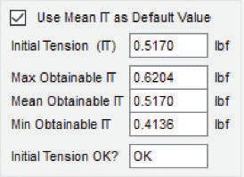
The ASD7 software 250 –always defaults to the 35 middle of this calcu- 225 –lated zone, as shown below. When using the ASD7 software, you can change the initial tension value once you uncheck the “Use Mean IT as Default Value.” Small adjustments here will Torsional stress (uncorrected) caused by initial tension (MPa) 200 175 150 125 100 75 – – – – – –Preferred range Available upon special request 30 25 20 15 Torsional stress (uncorrected) caused by initial tension (10' psi) allow you to zero in Difficult 10 on the customer’s 50 – to control requested load. 25 –5
Any number under 4 6 8 10 12 14 16 the “Min Obtainable Index IT” will fall in the lower area of the chart Figure 1 above. Any number above “Max Obtainable IT” will fall into the upper two areas of the above chart.
There will be times when you get a customer blueprint that calls for a great deal of initial tension. It’s possible the design engineer doesn’t understand it and the computer can do the math. It happens. So, when going above the “Max Obtainable IT” you should check Figure 2 with your setup personnel to see what their equipment is capable of. Some machines can achieve higher initial “Spring Design Tips and Tricks” is a feature tension then other. Feel free to contact Rick Gordon, SMI’s technical director, or me with designed to help those who use the ASD software on a regular basis. If you have a question you would like addressed by Todd Piefer of UTS or Gary Van Buren, SMI’s technical adviany technical needs you might have at sor, please contact Van Buren at gvanburen2@ c.richard.gordon@gmail.com or gvan- gmail.com. buren2@gmail.com. n