15 minute read
Technically Speaking
Advances in Springmaking Materials — Part 3: Wire Drawing and Heat Treating
By C. Richard Gordon
(Editor’s note: Rick Gordon’s article was developed as part of the overall theme of “Advances in Springmaking.” This is the third in the series of articles on advances in springmaking materials.)
Advances in the production of springmaking materials over time have resulted in improvements in spring performance. Since the majority of springs are produced from carbon and alloy steels, production methods of these materials will be described here.
Production improvements have occurred in the areas of steelmaking, continuous casting, rod rolling, wire drawing and wire processing (heat treatment). Improvements in springmaking machine technology were discussed previously1 . Improvements in the areas of steelmaking and continuous casting2 and rod rolling3 were also discussed previously.
This article will focus on improvements in wire drawing and the patenting and oil tempering heat-treating processes.
Materials Design Philosophy
In the Fall 2019 issue of Springs4, I discussed the engineering concept known as the materials design philosophy, which can be used as a tool to better understand composition-property relationships. Briefly, the materials design philosophy shows the relationship between the composition of the material and the final product properties (Figure 1).
A material with a specific composition is processed in a given operation. The combination of the material and the processing results in a particular structure (metallurgical microstructure). The microstructure in turn results in the specific material properties. In reality, the process of design occurs from right to left. Engineers are interested in specific material properties, which in turn are dependent on the structure, which is a function of designed processing of a material with a specific composition.
Material properties such as tensile strength and ductility are determined through mechanical testing, which have been discussed in past Springs articles5,6,7,8,9,10 .
Composition Processing Structure Properties
Figure 1. Materials Design Philosophy
For the purpose of this article, the following figures are expanded to include our current processes of interest: Figure 2 — wire drawing and Figure 3 — patenting and oil tempering heat treatments. From a materials perspective, a goal of any process improvement is to improve the uniformity of the product as well as enhance product properties. From an operations perspective, a goal is to improve productivity with the attendant reduction in cost. Thus, the challenge is to obtain both the materials goal and the productivity goal; how to achieve the balance is a subject beyond the scope of this article.
For students who are interested in more detailed information on wire drawing and heat treating of wire in general, there are three excellent references: “Ferrous Wire Handbook11,” “Steel Wire Technology12” and “Wire Technology13” that I recommend for your bookshelf.
C. Richard (Rick) Gordon is the technical director for SMI. He is available to help SMI members and non-members with metallurgical challenges such as fatigue life, corrosion, material and process-related problems He is also available to help manage and oversee processes related to failure analysis. This includes sourcing reputable testing labs throughout North America, forwarding member requests to the appropriate lab and reporting results and recommendations. He can be reached at c.richard.gordon@gmail.com or 574-514-9367.
Composition Processing
Wire Drawing
Change Wire Size/Diameter &/or Shape
D1
D2
D1
Figure 2. Materials Design Philosophy – Expanded for Wire Drawing
Structure
Cold drawn structure Properties
Change Wire Properties: Tensile Strength, Ductility, etc.
Composition Processing
Patenting
Oil Tempering/Induction Tempering Structure
Ferrite & Pearlite
Quenched & Tempered Martensite Properties
Change Wire Properties: Tensile Strength, Ductility, etc.
Figure 3. Materials Design Philosophy — Expanded for the Patenting and Oil Tempering Processes
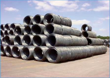
Figure 4. Coils of hot rolled wire rod.
Batch Cleaning and Coating
Hot Rolled Wire Rod
Heat Treating/Coating (If Necessary) Rod Drawing (If Necessary)
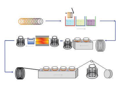
Finish Wire Drawing Coils on Stands or Reels
Figure 5. Producing steel wire from wire rod. (Courtesy of D.B. Coulston)
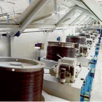
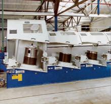
Figure 6. Modern wire drawing machine. (Courtesy of Morgan-Koch).
The Wire Drawing Process: First Step — Scale Removal
The starting material for carbon and alloy steel wire is hot rolled wire rod produced as coils, as shown in Figure 4. The weight of the coils is different depending on the producing mill but generally falls in the range of 4,000 to 6,000 lbs.
During the cooling process of wire rod, scale develops on the wire rod surface. The composition of the scale can be controlled by the cooling practice used, which in turn will depend on the customer’s planned scale removal method.
Wire rod can be descaled mechanically or chemically. Mechanical methods include reverse bend descaling, sanding and shot blasting. Reverse bend descaling is done in line with the wire drawing machine and can be combined with sanding, rinsing, coating with a lubricant carrier and drying prior to wire drawing. In most cases, shot blasting is done as a batch process but can also be done inline.
Chemical methods use either hydrochloric or sulfuric acid mostly in batch cleaning processes, which may include rinsing, zinc phosphate coating, coating with a lubricant carrier and drying. Many high carbon spring wire products are processed this way.
Figure 5 shows a general schematic of wire processing that can be adapted to several processes. In this schematic, batch cleaning with acid is used. Following batch cleaning, wire rod is transported to short term storage or directly to the wire drawing machine. Once the wire rod is prepared, the material is drawn through a wire drawing die in a single step (pass) or multiple steps (passes), depending on the product being produced. Over time, there has been a dramatic improvement in wire drawing speeds and product quality due to wire drawing machine equipment improvements (cooling and sensor technology), lubrication improvements (lubricant composition and pressure dies) and wire drawing die improvements (material and internal geometry). Control of temperature in wire drawing is critical for maximizing wire ductility.
Wire rod can be drawn to the finished product size or to an intermediate size for patent heat treating. Patent heat treated wire is then drawn to the final size with the package being coils on stems or reels. Wire rod can also be patent heat treated as a first step.
Figure 6 shows a modern multi-pass wire drawing machine that might be used to produce music spring wire. The machine has tuner rolls for tension control between passes and narrow gap cooling for exceptional heat removal from the wire on each draw block.
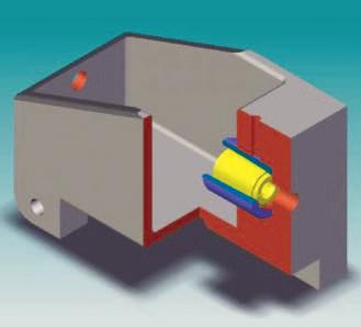
Figure 7. Schematic of a simple wire drawing die box.
Carbide Die or Nib
Bell Radius
Entrance Angle
Approach Angle Steel Casing
Back Relief
Bearing or Land Stainless Steel Cap and Case
Carbide Pressure Insert Carbide Drawing Insert
Figure 8. (left) Cross-section of a tungsten carbide wire drawing die. (Reprinted with permission of the Wire Association International. All rights reserved. www.wirenet.org). Figure 9. (right) ParaLoc Pressure Die System (US Patent No. 5,402,664)
Figure 7 shows a schematic of a wire drawing die box included on each pass of the wire drawing machine shown in Figure 6. The chamber on the left is a box for holding the dry powder lubricant. The yellow insert holds the wire drawing die.
Figure 8 shows a cross section of a tungsten carbide wire drawing die. This is the tool that comes closest to the wire surface, only separated by a lubricant boundary layer. The impact of wire drawing die approach angle on high carbon wire torsional ductility was discussed during the SMI Metal Engineering eXpo 201914 . Changes in wire drawing die bearing angle designed to change the stress distribution at the wire surface from tensile to compressive was also discussed at the SMI MEE 2019 event15 .
Pressure dies have been adopted almost universally for high volume wire drawing in the U.S. and around the world. The Paramount Die Company introduced the ParaLoc pressure die system in the 1990s (Figure 9). The patented die system maximizes the life of the drawing insert (die life) through improved lubrication. Users also found improved lubrication (less friction) produced a more uniform surface and reduced the drawing force required, thus lowering electricity consumption (cost). Originally conceived as a two-die system, the first die was intended to simply guide the wire into the draw die. Through experimentation, it was found that the residual lubricant film thickness on the wire could be increased dramatically when the guide die was sized to a diameter within 10 percent of the wire diameter. Improvements in the tungsten carbide inserts resulted from the reduction of tungsten carbide particle size balanced the with right amount of cobalt binder.
Patenting Heat Treatment
For those interested in history, in 1854 James Horsfall of Birmingham, England patented a heat-treating process that produced wire with high tensile strength and good ductility from high carbon eutectoid steel. This high-quality steel wire was called patented wire and heat treatment for making it was called patenting, as it is to this day.
Patenting is a heat treatment applied to medium carbon and high carbon steel before wire drawing or between drafts during drawing. In the early 1960s, it was a common practice to patent all steel rods containing between 0.40 percent and 0.90
1200
(˚C) Temperature
1000 800 600 400 200 0
Heating Soaking Cooling
Transformation
0 5 10 15 20 25 27.5 32 37 42 47 52 57 62 67 69.5 73 78 83 88 Time(s)
Figure 10. Typical Patenting Process11. (Reprinted with permission of the Wire Association International. All rights reserved. www.wirenet.org).
percent carbon before wire drawing. With the introduction of the Stelmor controlled cooling process, a rolled rod could be drawn without a post rolling patenting heat treatment. This led to the introduction of Type 1 music spring wire16 . Patenting (with a cooling method other than air) is required for Type 2 music spring wire processing. Air patenting, which produces a microstructure similar to the Stelmor process, is not allowed for Type 2 product.
Why is that? Patenting is performed on individual strands of wire in a linear manner rather than as a coil or loop form on the wire rod mill. Loops can overlap on the Stelmor conveyor and affect the cooling in those local areas of contact. As a result, the uniformity of microstructure and resultant mechanical properties along the patented wire or patented wire rod are superior.
Patenting involves four stages as shown in Figure 10: Heating, soaking, cooling or quenching, and transformation. Heating rod or wire can be done in several ways: in an open fired furnace containing a lean combustion mixture or in tubes containing an inert gas, in molten lead, in molten salt, in a fluidized bed, using direct electric resistance heating or induction heating. Heating is required to transform the steel structure to austenite. The rod or wire is held (soaked) at a constant high temperature for an appropriate time to homogenize the material. This is an important step in patenting as well as in the oil tempering process. Cooling from the soaking temperature can be done in air, molten lead, fluidized bed, or molten salt for transformation of the microstructure. The optimum transformation
Ae3
Isothermal Annealing
Temperature Cooling Curves
Ms
Mf
Product
Ferrite and Pearlite
Time — Log Scale
Figure 11. Isothermal annealing or patenting process superimposed on a time —– temperature — transformation (TTT) diagram.
temperature depends on the chemical composition of the material and the mechanical properties needed for wire drawing or in the final product.
The time-temperature curve shown in Figure 10 shows plateaus both on heating and cooling. The short time at constant temperature on heating corresponds to the endothermic reaction due to the crystal structure change from pearlite (ferrite and Fe3C) to austenite. The plateau that occurs at the end of cooling corresponds to the exothermic reaction where the austenite transforms to pearlite.
The metallurgical goal of patenting is to produce a steel wire or wire rod with a uniform microstructure of pearlite (primarily) and ferrite with sufficient ductility for wire drawing. The amount of each constituent will be dependent upon the steel composition, cooling method and transformation temperature. Patenting is sometimes described as isothermal annealing because the greatest uniformity of pearlite is produced in this way. Figure 11 shows a schematic of patenting cooling and transformation process superimposed on a TTT diagram. Process developments have resulted in patent wire products with improved ductility17 .
As shown in Figure 12, the microstructure of pearlite has a lamellar appearance. The lighter appearing lamellae are carbide (Fe3C — cementite) and the darker microstructure is ferrite. As the transformation temperature is lowered, the interlamellar spacing gets smaller in the pearlite transformation portion of the TTT diagram. This results in higher tensile strength and reduction of area ductility in the wire or wire rod.
Oil Tempering Heat Treatment
Oil tempering is a term commonly used in the wire industry to designate a type of wire that has received a hardening and tempering heat treatment after it has been drawn to the desired size11 . It is somewhat of a misnomer because in the heat-treating

Figure 12. Electron micrograph showing microstructure of pearlite formed at 575°C (1067°F) in a eutectoid steel. Magnification: 15,000X. (Reprinted with permission, Association for Iron & Steel Technology).
process, oil is not used as a tempering medium. “Quenched and tempered” or “oil hardened” may be more technically correct. Because the term “oil tempered” has been used extensively throughout history and is commonly used, it is doubtful that it will be replaced.
Processing elements included in an oil tempering line are shown schematically in Figure 13. In the past, lines were designed with multiple elements for two or more wires processed in parallel. Austenitizing was done in direct fired or muffle tube type furnaces with atmosphere control. Wires were quenched in a temperature-controlled oil bath and tempered in a molten lead furnace. In addition to oil, quenching has evolved to include hot water and water treated with synthetic polymers as substitutes.
Lead was the heat-treating media of choice because of its high thermal conductivity. As environmental issues were identified and subsequent legislative actions taken, suitable substitutes were pursued which include induction, fluidized bed and molten salt. Some companies were able to have their lead furnaces grandfathered in and continue to use lead for heat treating today.
Induction heating technology has found a home in single strand oil tempering lines for larger diameter products (0.162 in. to 0.625 in. diameters)18 . Figure 14 shows a schematic of the single strand process, where induction heating is used for both the austenitizing and tempering elements of the process. The different options for quenching media are shown.
Figure 15 shows the heating and quenching options for a multifilament process used for smaller diameter wire products.
Figure 16 is a schematic of the quenching and tempering elements of the oil tempering process superimposed on a TTT diagram. It should be noted that the surface of the wire cools faster than the center, which results in a thermal stress gradient which can cause cracking problems with some alloys. The
Let-off Austenitize Quench Temper
Figure 13. Schematic of an oil tempering process line.
Conditioning/Shearing Take-up
type of quench media and temperature of the quench can be critical to success.
Once martensite is formed during quenching, the general effect of tempering is to precipitate and agglomerate carbide particles. The tempered martensite microstructure consists of carbide particles (light) dispersed in a ferrite matrix (dark), as shown in Figure 17.
Summary
Improvements in wire drawing and the patenting and oil tempering heat-treating processes described in this article can result in improvements in the uniformity of mechanical properties and wire quality for springs. n
References
1. McCoy, G., Advances in Springmaking, Springs, Spring 2021, p. 23. 2. Gordon, C.R., Advances in Springmaking Materials, Springs,
Spring 2021, p. 30. 3. Gordon, C.R., Advances in Springmaking Materials, Springs,
Fall 2021, p. 21. 4. Gordon, C.R., Springmaking Materials/Materials Design
Philosophy, Springs, Fall 2019, p.23 5. Gordon, C.R., Types of Tests Used to Characterize Springmaking
Materials — Part 1: The Tensile Test, Springs, Winter 2020, p.27 6. Gordon, C.R., Types of Tests Used to Characterize Springmaking
Materials — Part 2: The Coiling and Wrapping Tests, Springs,
Spring 2020, p. 27. 7. Gordon, C.R., Types of Tests Used to Characterize Springmaking
Materials — Part 3: The Torsional Ductility Test, Springs,
Summer 2020, p.17. 8. Gordon, C.R., Types of Tests Used to Characterize Springmaking
Materials — Part 4: Hardness Testing, Springs, Fall 2020, p.19. 9. Gordon, C.R., Types of Tests Used to Characterize Springmaking
Materials — Part 5: The Reverse Bend Testing, Springs,
Winter 2021, p.19. 10. Gordon, C.R., Types of Tests Used to Characterize Springmaking
Materials — Part 6: Fatigue Testing of Wire, Springs,
Summer 2021, p.21. 11. Shemenski, R.M., editor, Ferrous Wire Handbook,
WAI International Inc., (2008) 12. Per Enghag, Steel Wire Technology, 3rd Ed. (2003) Wiley-VCH 13. Wright, R.N., Wire Technology, Process Engineering and
Metallurgy, 2nd Ed., Elsevier, 2016 14. Gordon, C.R., Torsional Ductility as an Important Quality
Parameter for Spring Making Materials, SMI Metal Engineering eXpo 2019, Pittsburgh, Pennsylvania 15. Gordon, C.R., The Impact of Wire Drawing Die Geometry on
Development of Residual Stresses and Potential for Improved
Spring Fatigue Life, SMI Metal Engineering eXpo 2019,
Pittsburgh, Pennsylvania 16. ASTM A228 / A228M-18, Standard Specification for
Steel Wire, Music Spring Quality, ASTM International,
West Conshohocken, PA, 2018, www.astm.org 17. Bekaert US Patent No. 4,759,806 18. Becker, T. Induction Tempered Wire, Wire Forming Technology
International, October 2001
Single Wire Induction
Oil Hot Water Synthetic Polymer Induction
Figure 14. Single wire oil tempering using induction heating for austenitizing and tempering.
Configuration
Multi-wire Austentize
Direct Fire or Muffle Tube with ATM Control Quench
Oil Hot Water Synthetic Polymer Temper
Fluidized Bed
Figure 15. Oil tempering line options for multifilament smaller diameter wire processing.
Figure 16. Schematic of the quenching and tempering cycle of the oil tempering process superimposed on a Time — Temperature — Transformation (TTT) diagram.
Ae3
Temperature
Ms
Mf Surface
Customary Quenching and Tempering
Tempered to Desired Hardness
Center
Start of Transformation
Finish of Transformation
Log Time Tempered Martensite
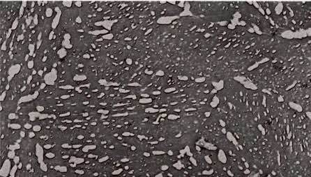
Figure 17. Electron micrograph showing microstructure of tempered martensite for a eutectoid steel. Tempering temperature 595°C (1100°F) Magnification: 15,000X. (Reprinted with permission, Association for Iron & Steel Technology).

