
10 minute read
Figure 3: Site images of PPSP in West Bengal


1.1.1 Pumped Hydro Storage
A PHS system works on the principle of electromechanical energy conversion. PHS facilities are large-scale energy storage plants that use gravitational force to generate electricity. Water is pumped to a higher elevation for storage during low-cost energy periods and high-renewable energy-generation periods. When electricity is needed, water is released back to the lower pool, generating power through turbines. A closed-loop PHS operates without being connected to a continuously flowing water source, unlike traditional pumped hydro storage, making pumped hydro storage an option for more locations. Reservoirs, if available naturally, are required to pump water from a low-lying water source during motoring mode to a high-altitude reservoir to store the energy in potential energy at height. The water is then released during the generating mode to run a turbine-generator set to generate electricity to be fed into the bulk-transmission network. In India, the state of West Bengal is amongst the front runners of utilizing PHS in its power network to manage system demand. The geographical location of West Bengal provides the edge to West Bengal State Electricity Distribution Company Limited (WBSEDCL) over other distribution utilities in terms of favorable sites for such storage systems. The Purulia Pumped Storage Project (PPSP) is one of the largest in the country. Based in the Purulia district, it is a-225 MW × 4 system. This project utilizes excess available power in the system during off-peak times to flatten the load curve. The project works in four operational modes: (i) generation, (ii) pumping, (iii) synchronous condenser, and (iv) line-charging (up to 400 kV bus) mode. The generation voltage is 16.5 kV. Figure 3 shows the plant and one of the tunnels.
Advertisement
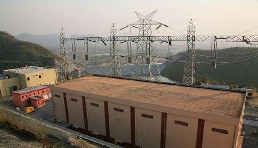
FIGURE 3: Site images of PPSP in West Bengal4
The major issues associated with such an energy storage technology are the long-gestation period, high-upfront capital required including extensive civil works. It is worth mentioning, the cost of generation, including its storage, is very low, however, the round-trip efficiencies are a bit low.
4 https://portald.wbsedcl.in/irj/go/km/docs/documents/WBSEDCL_DOCUMENTS/INTERNET/Website_ 28FEB2011/Puruliwa_Pumped_Storage_Project_2.html
Pumped hydro storage is more than 80% energy efficient through a full cycle, and the facilities can typically provide 10 hours of electricity, compared to about 6 hours for lithium-ion batteries. Despite these advantages, the challenge of PHS projects is that they are long-term investments – permitting and construction can take 3-5 years. This issue can be a major stumbling block for investors who would prefer short-term investment, especially in dynamic power markets which are evolving on a day-to-day basis.
1.1.2 Battery Energy Storage Technologies
A Battery Energy Storage System (BESS) converts electrical energy into chemical energy and stores a certain amount of energy considering the electrochemical conversion efficiency. The most commonly used battery chemistries for grid-level applications in the current scenario are based on lead, sodium, nickel, transition metals(vanadium, chromium, and iron), and lithium electrochemistry. The BESS is gaining wide acceptance for grid-level applications due to falling prices, and their unique features like quick response time, distributed energy/powerbalancing capabilities, and phased installation. Moreover, the batteries can be used for both power and energy applications. On the contrary, capacitors and flywheels are used only for power applications. Suitable selection needs to be done for specific grid-level applications since each chemistry has distinct characteristics, such as charge/discharge rate capability, energypower ratio, electrochemical conversion efficiency, depth of discharge, and life cycle. Some key definitions in the context of battery energy storage systems (BESS) are given here: 1. Battery cycle life: is defined as the number of charge-discharge cycles a battery can complete before its nominal capacity falls below 80% of its initial rated capacity. 2. Energy density: is the amount of energy that can be stored in a given mass of a substance or system. 3. Round-trip efficiency: Energy storage captures electricity in some manner and based on requirement transfers it to the grid. The ratio of energy put in (in megawatt hour or MWh) to energy retrieved from storage (in MWh) gives round-trip efficiency (also called AC/AC efficiency), expressed in percentage (%). 4. Energy capacity: The amount of energy that can be stored in a battery per MWh refers to the total energy that can be stored in a battery and the amount of energy that can be extracted in an hour. Energy capability is measured in terms of C. Higher is the C value, more current can be drawn from the battery, for example, lead-acid batteries have very high C values (up to 10C) while the value of C in lithium-ion batteries is significantly low (up to0.01C). 5. Energy to power ratio: It is defined as the rate of discharge or discharge time. Rated power (in MW) and capacity (the amount of energy the battery can deliver over time) are reported in
MWh. Mathematically, the division between capacity and rated power gives discharge time. 6. Power rating: The use of MW denotes the power rating of a battery; this means, how fast power can be charged or discharged from a battery. 7. C and E rates: In describing the battery’s technical specifications, discharge current is often expressed as C-rate, to normalize against battery design capacity, which is often varied based on battery chemistries. The C-rate is a measure of the rate at which a battery is discharged,
relative to its maximum capacity. A 1C rate means that the discharge current will discharge the entire battery in 1 hour. For a battery with a capacity of 100 Ampere hours (A-h), this equates to a discharge current of 100 A. A 5C rate for this battery would be 500 A, and a C/2 rate would be 50 A. Similarly, an E-rate describes the discharge power. A 1E rate is the discharge power to discharge the entire battery in 1 hour. 8. Response time: It is defined as the time taken by a storage system to reach nominal power after a standby period. 9. Usable capacity: The amount of electrical energy (in kWh) that can be discharged from a storage system as per the manufacturer’s specifications, although sometimes also referred to in percentages as a ratio of usable capacity-to-installed capacity.
Lead-acid batteries
Lead-acid batteries have been one of the most prominent rechargeable electrochemical devices, predominantly used in uninterrupted power sources (UPS) for providing backup supply to various consumer categories during power outages. Lead-acid batteries are generally designed in two forms, namely, (i) vented lead-acid (VLA) and (ii) valve-regulated lead-acid (VRLA), with a power range up to a few megawatts and energy range up to 10 MWh. The VRLA requires lower maintenance as compared to VLA. Lead-acid batteries, a mature technology, are relatively cheaper than other battery technologies and have decent reliability and performance; however, low specific energy and cycle life pose a barrier in their large-scale deployment. To overcome these challenges, more recent advancement in lead-acid batteries involves the use of carbon in one or both of the electrodes. The introduction of carbon material in the form of ultra-capacitors enables the battery to operate for a longer duration and more effectively in a partial state of charge application than traditional lead-acid batteries. The composition of hybrid lead-acid and ultra-capacitor design has given the battery the ability to operate continuously in the highest efficiency region and avoid the corrosion and sulphation of active electrode material.
Flow batteries
The flow batteries are designed with two separate tanks which consist of electrolytic solutions, one tank act as a cathode material while the second tank is represented as an anode material. The electrolytic solution is passed through a membrane to generate electricity during discharging while in the case of charging the energy is stored in the form of chemical energy. Flow batteries exhibit unique features in a way that the power and energy capacity of the battery pack is completely decoupled. The flow batteries are typically an aqueous-based solution. Their cell voltage ranges from 1.0 to1.8 V, this prevents hydrolysis of water. Non-aqueous electrolyte flow batteries have high-open circuit voltage, so they have the potential for high energy density; however, these batteries are still under the development phase. The temperature range of flow batteries in an operating window is – 10°C to 50°C. Owing to the aqueous electrolyte (non-flammable), flow batteries are safe and have long cycle life (does not depend on the depth of discharge (DOD), energy depends on tank volume and electrolyte concentration and power determined by stack area. These batteries are most costeffective for longer duration applications, besides, can provide fast ramp rates. Flow batteries’ cycle life range is 2,000-20,000 cycles, and round-trip efficiency of 65%–85%. These batteries have certain drawbacks such as high-maintenance requirements, the large space requirement for largesized batteries, the non-modular nature of the installation, and complex monitoring and control
mechanisms for battery operation. Vanadium redox flow batteries are primarily commercialized by a few companies, for example, the US-based UniEnergy Technology (UET) and Vionx Energy, the German-based Gildemeister, and Sumitomo Electric from Japan.
Sodium-sulfur batteries
Sodium-sulfur battery is a molten salt-based battery that is constructed from liquid sodium and sulfur, is known to exhibit high-energy-density, longer cycle life, and high-round-trip efficiency. The composition of the material used to construct this particular battery is relatively inexpensive than the material used in other batteries. Sodium–sulfur battery has found a wide range of applications in an electricity distribution network such as grid support, solar photovoltaic (PV)/wind plant integration, and high-value proposition for different applications on islands. The technology has a great potential for grid services since it has a long discharge time and can respond precisely to improve power quality issues in the grid. It is a reliable technology, and the largest installed capacity of a single unit of 34 MW/245 MWh has been deployed in Aomori, Japan. The system was installed for wind stabilization. The technology is only suitable for stationary applications. The major drawback of this battery is the high-operating temperature which rangesfrom300–350°C. Japan has been considering this battery technology as an alternative to lithium-ion to reduce the imports of rare earth metals from the countries that control supply chains, extraction, and reserves of metals used in the manufacturing of lithium-ion batteries.
Lithium-ion batteries
Lithium-ion batteries are a well-known technology for portable electronic devices because of their unique features like high energy density and relatively low weight. In the past few years, lithiumion batteries are being considered to be the most attractive for grid-level applications due to their several advantages over other chemistries like high-specific energy density, high charge/ discharge rate capabilities, a large number of cycles, lower self-/cycle degradation, and higher round-trip efficiency. Owing to the increasing demand for lithium-ion batteries in the automotive industry and consumer electronics, in addition to the grid-level application, the cost is expected to fall in the coming years. In most of the commercially available lithium-ion batteries, the anode is lithiated graphite or lithium-titanate while the cathode is made up of either lithium metal oxide or lithium phosphate. The different chemistries of lithium-ion which are commercially available for different applications include LiCoO2 (LCO), Li2MnO3 (LMO), LiFePO4 (LFP), LiNiMnCoO2 (NMC), Li4Ti5O12 (LTO), and LiNiCoAlO2 (NCA). These different chemistries showcase different performance, cost, and safety features that can be utilized for a variety of applications. As an example, LCO batteries are predominantly used in handhold electronics devices due to their high energy density and low weight. On the other hand, LFP, NMC, NCA, and LMO offer low-energy-density, but longer cycle life and inherent safety, thus these batteries, especially NMC and LFP are being utilized for grid-level applications. Moreover, LTO batteries offer high performance, higher cycle life, excellent safety feature, and higher charge/discharge rate (up to 10 C) however; their specific energy is low as compared to other lithium-ion batteries. Despite several technological advantages of LTO batteries over other lithium batteries, the higher cost of LTO has been a primary hurdle in their large-scale deployment. Table 1 gives the comparison between different battery chemistries to understand the drawbacks and benefits of available technologies in the market.

