
28 minute read
Concrete Beam Strength vs. Serviceability


d N.A.
εt T = Asfy
Figure 1. Strain and stress diagrams for concrete beam for strength design.
N.A.
T Figure 2. Serviceability stress diagram.
EnginEEr ’s notEbook
aids for the structural engineer’s toolbox
Engineers largely appreciate the differences afforded between allowable stress design (ASD) and ultimate strength design (LRFD) methods, and we generally follow the prescribed protocol for each procedure without much trouble. However, even though the ASD approach has been largely supplanted by LRFD, certain occasions require that we revisit the old ASD theory for reinforced concrete (or masonry). As such, it is appropriate that we recognize the subtle and not-so-subtle differences between the two. Strength design for reinforced concrete has been the norm for many years. Its basic premise is that we design for a specific failure mechanism in the element and ensure that it is ductile. We commonly assume (among other things) that reinforcement yields and concrete crushes, preferably in that order. With this concept in mind, we can readily apply yield and crushing stresses to the steel and concrete, respectively, and develop overall capacity boundaries and limitations. We also apply load and strength reduction (φ) factors to the design to ensure that the likelihood of breaching said boundaries and limitations is acceptably small. The current strength design methods are a far cry from the previous working stress design approaches used for reinforced concrete. We no longer need to calculate depths to neutral axes based on transformed sections, nor do we need to use the parallel axis theorem to calculate a cracked moment of inertia. However, these traditional design approaches must still be examined as we look at serviceability. The actual failure mechanism of the member is an extreme condition that is not easily adapted to ordinary serviceability conditions. Hence, strength design methods are not well-suited to addressing serviceability issues, since the goal of the latter is not to predict how much deformation will occur in steel as it actually yields or in concrete as it is actually being crushed. Working stress design methods typically use the same load combinations for strength and serviceability, but we must often develop two concurrent combinations, one set for strength design and another for serviceability, when using contemporary methods. A potential error in the design of reinforced concrete is to mismatch design values and/or section properties between strength and serviceability design methods. An example of this is the depth to the neutral axis of a reinforced concrete beam, often assigned the variable c. For strength design, this occurs where the strain is zero when assuming a positive (compressive) strain of 0.003 (εcu) for the concrete on the top side, the net tensile strain (εt) in the rebar at the bottom side, and linear variation between them. The value of c is calculated by using similar triangles. The stress diagram to complement this is then easily derived from the assumed concrete crushing capacity and reinforcing steel yield strength, as shown in Figure 1. For serviceability design, strain may not necessarily be a consideration, but the stress diagram is taken as that shown in Figure 2. This would apply to both a serviceability limit state, Concrete Beam Strength vs. Serviceabilityfor calculating cracked and effective section properties, and the maximum working stresses in the concrete and reinforcement, used to assess strength in the By Jerod G. Johnson, Ph.D., S.E. older methodology. For this diagram, the relationships are derived using transformed sections and assuming elastic behavior. As an example, consider a 12-inch wide by 18-inch deep concrete beam (f'c = 4,000 psi) reinforced with three #6 bars (fy = 60,000 psi). Assuming that the span exceeds the limitations of table 9.5(a) in ACI 318-11, the strength design must be accompanied by a check for serviceability (deflection). For strength design, the depth to the Jerod G. Johnson, Ph.D., S.E. neutral axis (c) is 2.28 inches. For serviceability, (jjohnson@reaveley.com), is a the depth to the neutral axis is nearly double principal with Reaveley Engineers + this, at 4.51 inches. Hence, for valid design, the Associates in Salt Lake City, Utah. engineer must be cognizant of which limit state is under consideration (strength or serviceability). In addition, the correct application of equations must accompany the method being used. Derived values between the approaches must never be interchanged. Interestingly, leading textbooks often assign the variable c as the depth to the neutral axis regardless of design consideration (strength vs. serviceability), hence the potential for confusion. In actuality, the behaviors reflected in the compared numerical models of the flexural mechanism are vastly different, one corresponding to the ultimate flexural failure of the member, the other to the stresses that may develop under normal service loading. One addresses behavior as the flexural strength threshold is breached, the other behavior that affects the comfort of the occupants that it supports.▪
Rural Philippine Shelter Construction Structural Engineering Challenges By Gustavo Cortes, Ph.D, P.E.
Who would have thought that designing a 10-foot (3 meter) by 13-foot (4 meter) structure would present so many unique challenges? The structure, a single family shelter, seemed very straightforward at first; however, a field visit to Leyte Island in the Philippines proved otherwise. The task was to develop structural drawings for a shelter unit that is being provided to the most vulnerable victims of super typhoon Haiyan. Nearly 1,080 units are to be built by July 2015. This article presents some of the challenges encountered, including anticipation of load conditions, availability of materials, and quality of materials received. On November 8, 2013, super typhoon Haiyan hit the Philippines, devastating the Visayan Islands in Central Philippines, particularly the islands of Samar and Leyte. The super typhoon, locally known as Yolanda, had winds exceeding 190 mph (300 km/hr), making it equivalent to a hurricane Category 5 on the Saffir–Simpson hurricane wind scale. The strong winds and rain brought flash floods, landslides and immense destruction. This mega storm killed more than 6,200 people, damaged 1.1 million homes, and left some 4.1 million people displaced (USAID, 2014). Several non-governmental organizations (NGOs) mobilized personnel to help restore the community. Medair, a Swiss based NGO, rapidly responded to the humanitarian crisis by reaching out to remote and rural communities that had not received assistance. Medair found almost total devastation in the Dulag municipality, 19 miles (30 km) south of Tacloban. The typhoon had damaged or destroyed 9,004 houses (81% of all homes); leaving approximately 44,000 people, out of a population of 53,883, displaced from their homes (Medair, 2013). Medair’s shelter construction project is now underway. After an assessment of the needs and the living habits of the local population, architects from Medair rapidly developed a prototype shelter. Figure 1 shows elevation views of the structure in its first phase. Initially, the unit is enclosed by means of a tarp, allowing for immediate occupation and future expansion. This initial phase provides 129 square feet (12 square meters) of living area; however, the owners could increase its size to 301 square feet (28 square meters) as their income allows. This can be accomplished by adding two rooms, one on each side of the house. Once the main concept was developed, the structural design started. Fundamental principles of design for high-seismic and high-wind loads were followed. Many aspects of the design and construction had unique challenges. These are discussed next with the intention of helping the readers understand challenges encountered when designing relief structures in undeveloped regions.
Anticipation of Load Conditions
Several complications arose when determining the design loads for the shelters. First, the National Structural Code of the Philippines: NSCP Volume 1 (ASEP, 2002), was used to determine the design wind loads. These were compared to ASCE 7 (ASCE, 2010) and results were very similar. The unique challenge here was to obtain the NSCP and to learn how to implement it. Once the design was nearly completed, a visit to similar relief shelters built in the region revealed two new issues that had not been
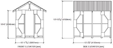
Figure 1. Shelter elevation views.
considered. First, because of potential flood exposure in many locations, the floors were not on the ground as initially thought; instead they were attached to columns. What was really worrying was the fact that, given the approximate 13-foot clear height of the roof ridge, and the floors often being placed at around mid-height of the columns, a two-story house was basically created. This produced a significant deviation from the original design, increasing the load on the columns. Secondly, with regard to seismic loads, what was initially thought to be a lightweight structure with insignificant mass, coming mostly from roof dead loads, now became a structure with a mass at the elevated floor location as well. Another unique aspect of the loading conditions was created by the enclosure used for exterior walls. The initial phase included the distribution of a tarp to be placed around the shelter to provide protection against wind and rain. Accordingly, the lateral-force resisting system was designed to withstand the forces generated by the wind pressures acting on the membrane. Several houses visited, however, had not used the provided membrane and were instead using a locally produced thin fabric called Amakan. This fabric is made by weaving bamboo strips at 90 degree angles (Figure 2). These fabrics have large gaps between the bamboo strips, which allow for wind to flow through the shelter. This membrane is also very likely to let water enter the shelter even during moderate winds. Under high wind pressures, the Amakan fabric will possibly fail, allowing wind to flow through the
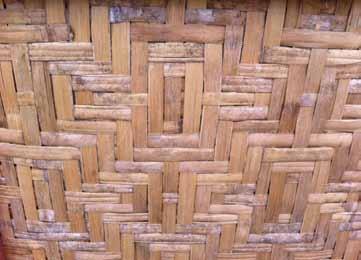
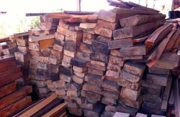
Figure 3. Local coco lumber supply.
shelter, reducing wind pressure on the main lateral-force resisting system but increasing the pressure at roofing elements. The solution, if all the scenarios are to be considered, is to design the lateral-force resisting system for the maximum loads coming from the full wind pressure, when the structure is enclosed, while the roof should be designed to withstand uplift from an open structure.
Availability of Materials
Coco lumber is a natural resource widely available in the Philippines. It is extensively used for housing construction in rural areas because of its availability and relative low cost. An extensive amount of coco trees fell during super typhoon Haiyan, increasing the supply of this inexpensive material. Figure 3 shows a typical coco lumber supplier found by the side of a major road in Tacloban. However, coco lumber requires careful processing and strict quality control for it to serve as structural lumber. Untreated coco lumber exposed to weather is very susceptible to fungi and termites, which can destroy the hard portion of the trunk in less than 2-3 years and the soft portion in just a few months (Arancon, 2009). Although treatment would increase its life span, treated coco lumber was not readily available in the region. Furthermore, available coco lumber from local supplies varied greatly in dimensions and density. Much of it was cut using chainsaws, resulting in uneven pieces of lumber. Given the uncertainty of the quality of the coco lumber found, it was not used for structural elements. However, in order to promote the local economy, coco lumber was specified for non-structural elements that will not be directly exposed to the weather. It is important to aid the local economy as much as possible without compromising the structural integrity of the shelters. The construction managers consulted several suppliers in the region and decided to import treated No. 1 Grade Radiata Pine framing from New Zealand. This wood species is not included in the National Design Specification® (NDS®) for Wood Construction (AWC, 2012), normally used for design of wood structures in the United States. Thus, the New Zealand timber construction standard, NZS 3603 (1993) had to be consulted to find the design strength of these species. Upon inspection, it was found that the strength value given does not include the same adjustment factors as the US design specification. Thus, these strength values could not be applied directly in the NDS member strength equations. Instead, strength values were adjusted according to New Zealand’s design standard. It would be erroneous to assume the properties of the lumber used, based on a typical grade of species group normally found in the USA. As an illustration, the Table compares the adjusted strength values, ignoring stability, for No. 1 Radiata Pine framing with those
1Design values account for a strength reduction factor (φ) of 0.8 for timbers and a duration of load factor (k1) of 0.8 for medium duration loads (live load). Note that base values are given in LRFD format. These values are based on New Zealand’s design code (NZS, 1993). 2Design values account for the corresponding format conversion factor (KF), resistance factor (φ), and assume a time effect factor ( λ) of 0.8 for the load combination of 1.2D + 1.6L (occupancy).
Strength Value (LRFD) No. 1 Radiata Pine Framing (psi)1 Southern Pine No. 2 (psi)2
% difference
F*bn 928 2591 94.5
F*tn 371 1426 117.4
F*vn
F*cn 353 302 15.6 1392 2851 68.8
of No. 2 Southern Pine for a 2x4 section. Note how the difference can exceed 100%. Although this point may seem obvious, verifying other designers’ calculations for overseas shelters, on two different occasions, revealed the use of design properties from a typical USA species group/grade even though the wood used was a local wood with significantly different properties.
Quality of Materials Received
Another challenge was to obtain materials with the requested quality. Often the material received was substandard. One example is the requested marine plywood, which ended up being regular interior plywood whose product name was marine plywood. Another example is the wire used to tie purlins to rafters, which corroded in a short time after installation because the galvanization was inadequate. To complicate things further, nails provided did not follow the same dimensions as those in the United States, but they were instead a little shorter. For example, a 16D common wire nail in the US has a 3½ inch length. In the Philippines, nails provided were often only 3 inches long. This was solved by specifying the required length and diameter of the nails.
Conclusion
The intentions of this article are to share the experience encountered when designing a transitional shelter in an undeveloped region of the Philippines, and to raise awareness for future relief projects. It is crucial for a design team to research and anticipate many of these challenges before finalizing the design phase, in order to better serve these communities. An early site visit is necessary since it can potentially reveal any challenges and possible solutions to those challenges. This relief effort is currently underway with 1,080 units to be built by July 2015. The aspects discussed in this article were taken into account, and included in the construction plans and documentation currently used by the construction crews. This project is a great example of how the structural engineering profession can help underserved communities.▪ Gustavo Cortes, Ph.D, P.E., is an Assistant Professor of Civil Engineering at LeTourneau University. He may be reached at GustavoCortes@letu.edu.
The online version of this article contains detailed references. Please visit www.STRUCTUREman.org.
By Eric R. Ober, P.E., S.E. and Robert P. Antes
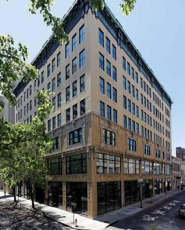
Parkway 301, formerly the Shenandoah Building, is a transitional masonry structure located in the Downtown Historic District in Roanoke, Virginia. The seven-story building, originally constructed in 1910 and vertically expanded in the early 1920s, had office occupancy over ground floor retail since its opening. Recently, the building was adapted to house ninety residential apartments on the upper floors over renovated ground floor retail space. Insufficient documentation of the existing construction in adaptive reuse projects challenges designers and contractors. In the case of the Parkway 301, hidden conditions overwhelmed all other structural challenges of the project.
Project Background
Roanoke is located in the southwest portion of Virginia and is the state’s eighth largest city. Its population grew substantially in the first half of the twentieth century. A number of the buildings of this time period in the Downtown Historic District remain standing and have undergone renovation in recent years. Parkway 301 is among the most recent (Figure 1). The building was initially constructed in 1910 as a rectangular three-story reinforced concrete office building over a one-story basement. The footprint is approximately 120 by 95 feet. In the early 1920s, the Shenandoah Life Insurance Company
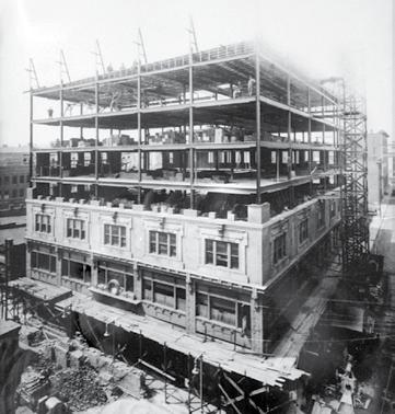
Figure 2. Parkway 301 (then The Shenandoah Building) during 1920s vertical expansion. Figure 1. Parkway 301 after renovation. Courtesy of Peter Aaslestad, Copyright 2014.
purchased the building and commissioned a four-story steel-framed vertical expansion with a U-shaped plan opening to the south (Figure 2). The west, north, and east wings surround a central light well which occupies a footprint of 40 by 40 feet. Exterior masonry walls are primarily composed of brick and terra cotta, and infilled tight to the concrete and structural steel frame. This type of wall construction was common in buildings of the early 1900s, where designers intended to maximize the usable interior space and relied on the erroneous assumption that masonry construction was effective waterproofing for the embedded structural framing.
Project Description
The building remained largely unaltered until purchased by Chapman Enterprises Inc. in 2012. Chapman retained the project architect, Baskervill, to design an adaptive reuse of the building to include ninety residential apartments on the upper six floors over ground floor retail space. Baskervill engaged Simpson Gumpertz & Heger Inc. to provide structural engineering services for the project. The major structural components of the renovation initially included a new full height interior egress stair (basement to seventh floor), reconstruction of the interior lobby slab inside the building to meet ADA requirements, lowering portions of the basement slab to create adequate headroom for tenant amenity use, and demolition of portions of the third and fourth floors to extend the light well into the original 1910 construction to accommodate additional apartment units. Field Investigation Drawings for the building were non-existent. The existing building construction was extensively investigated while still partially occupied.
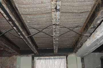
Figure 3. Draped mesh slabs and steel-lumber joists at upper levels.
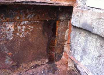
Readily-visible components were measured and hidden structural members were probed at representative locations. Due to the age of the existing structural steel, weldability could not be presumed by default. Samples were retrieved from columns and beams and tested with the finding that the steel is consistent with ASTM A36 in terms of metallurgy and thus easily weldable. The 1910 construction is framed with one-way composition slabs (reinforced concrete ribs between clay tile fills) spanning between reinforced concrete beams and columns. The 1920s vertical addition has steel columns stacked over the existing concrete columns below, with the exception of three columns. Three upturned east-westspanning transfer girders at the fourth floor carried the loads of the three offset columns above to the existing concrete columns below. The girders, encased in brick, penetrated the building envelope into the light well such that each girder was located on the interior and partially on the exterior. The presence of some unusual structural assemblies complicated structural analysis of the existing framing. Concrete slabs and beams at the 1910 construction are reinforced with Kahn bars, developed by Julius Khan and patented in 1892. These bars were rolled in various sizes with a diamond-shaped center and horizontal projecting flat plate wings. The projecting plates were cut free from the core in a regular pattern and bent upwards at 45 degrees so that the bars served as both flexural and shear reinforcement. At the 1920s construction, draped mesh concrete slabs are supported by steel-lumber joists at close spacing, which span between structural steel girders. The name is a misnomer as there is no “lumber” in these joists. They are composed of back-to-back cold-bent C-shaped steel sections (similar to modern cold-formed steel studs) and were introduced to be a component of light framed floor systems economical in situations where wood joists were traditionally employed (Figure 3). Asbestos-laden materials hindered completion of all of the desired probes (including those at the existing upturned transfer girders). With no visually apparent signs of structural damage or excessive deflection, further probing was deferred to the construction phase. Discovery While non-structural demolition was underway, the general contractor uncovered significant hidden structural damage around the perimeter of the light well at the fourth floor. At the north side, two concrete beams, carrying heavy masonry walls and spanning the width of the light well, were found to have wide full width diagonal cracks at their supports (Figure 4). Along the west side, the upturned transfer girders were uncovered and found to be riveted built-up steel sections comprised of angles and plates. Where the girders penetrated the building envelope near midspan, long-term water infiltration substantially corroded the steel resulting in areas of full section loss of the web and partial section loss of flanges (Figure 5). Along the south side, the soffit of each of the concrete spandrel beams across the width of the light well and into the adjacent bays had severe spalling and moderate reinforcement corrosion. Steel lintel angles over the punched window openings in the south wall were severely corroded.
Figure 4. Severely cracked concrete beam at north side light well.
Response
The contractor halted construction while the newly exposed existing conditions were evaluated by the structural engineer. Each of the conditions was determined to require repair intervention. The need for temporary shoring was unclear since there was no visually apparent deflection of the structure; however, the steel girders were believed to be marginally stable based on the extent of corrosion damage. The structural engineer undertook a series of structural analyses to evaluate the effects of measured steel girder corrosion on building temporary stability, including consideration of potential alternative load paths (such as Vierendeel frame behavior of the supported structure above). No structurally adequate load path was identified. Temporary shoring of the structure supported by the transfer girders was installed to maintain building stability while permanent repair options were contemplated. After the building was shored, the contractor resumed construction in unaffected areas.
Repairs
The concentration of structural deterioration challenged the designers and contractors to work together to develop the most efficient approaches to resolving and repairing the damage. At the north side of the light well, there was adequate headroom to enable
installation of new steel beams below both of the damaged concrete beams. The south spandrel beam damage was the result of poor construction quality (inadequate reinforcement cover) but had not resulted in significant steel section loss for the Kahn bars. Conventional concrete repairs were implemented. The most serious structural concerns were with the three steel transfer girders. The range of steel girder repair options considered included repair in place, elimination of the transfer by adding new columns to new foundations, and replacement of the transfer girders inside the enclosed portions of the building. Repair in place was eliminated from consideration early. The original ill-conceived design concept of penetrating the building envelope could not be easily made more reliable. Extending new columns to new foundations was technically feasible but architecturally unacceptable in the first floor retail space. Thus the last option, new transfer girders inside the building, was implemented. At Parkway 301, substantial clear headroom was available below the second floor to accommodate the new girders. The final repair design consists of new structural steel transfer girders spanning directly below and parallel to the original transfer girders above, maintaining the original gravity load path to the foundations. Work included the following: • Erecting a pair of parallel wide flange girders below each transfer girder above. • Adding steel sections and post-installed anchors around the existing columns to receive the new girders. • Adding new columns to extend the transferred columns down to the new transfer girders. • Modifying the existing transfer girders to retain the interior portions (intimately anchored with the existing steel columns above) and eliminate those portions outside the building envelope.
• Partially pre-loading the new girders by hydraulically jacking prior to releasing the shores. Construction schedule was a significant consideration in the overall approach to the repairs. These repairs had to be completed before other schedule-intensive work, such as structural demolition at the light well, could be implemented. Project funding hinged on meeting occupancy goals established at the conceptualization of the project. The contractor worked with the design team to develop expedient details and, ultimately, the repairs were completed in a timely fashion to allow the overall project to meet critical deadlines.
Lessons Learned
Hidden structural deterioration is commonly uncovered in renovation or adaptive reuse projects. In the case of Parkway 301, visual observations alone would have misled the design team into the erroneous assumption that “all is well”. Diligent investigation of existing conditions, regardless of the availability of drawings and often including destructive probing of representative hidden conditions, is always recommended. The success of the Parkway 301 project is a testament to the hard work of all parties involved and a team approach to achieving the Owner’s vision.▪ Eric R. Ober, P.E., S.E., is a Senior Project Manager at Simpson Gumpertz & Heger’s Washington DC office. Eric can be reached at erober@sgh.com. Robert P. Antes is a Staff II-Structures at Simpson Gumpertz & Heger’s Washington DC office and serves as the Project Engineer on all types of repair and rehabilitation projects. Robert can be reached at rpantes@sgh.com.
ADVERTISEMENT–For Advertiser Information, visit www.STRUCTUREmag.org
CORROSION REPAIR AND STRENGTHENING SOLUTIONS FOR THE CONCRETE INDUSTRY

For over 20 years, QuakeWrap has pioneered advanced construction technologies utilizing Fiber Reinforced Polymer (FRP) products. Our patented FRP products have been selected to rehabilitate and retrofi t structures worldwide, with award winning results. Our products are custom engineered to provide the savings, speed, versatility, and durability owners, engineers, and contractors need to complete projects on time and within budget.


RC COLUMNS PCCP PIPES BEAMS & SLABS CELLULAR TOWERS
CONCRETE PILES PARKING GARAGES CHIMNEYS WALLS


VISIT OUR BOOTH AT THESE UPCOMING EVENTS!


NASTT No-Dig Show • March 15-19, 2015 • Denver, CO Bakken Oil Product & Service Show • April 15-16, 2015 • Dickinson, ND ACI Spring Convention • April 12-15, 2015 • Kansas City, MO ASCE Pipelines Conference • August 23-26, 2015• Baltimore, MD AAPA Annual Convention • October 11-14, 2015 • Miami, FL

(866) 782-5397
QuakeWrap.com |


Don't replace. Repair in place.Repair
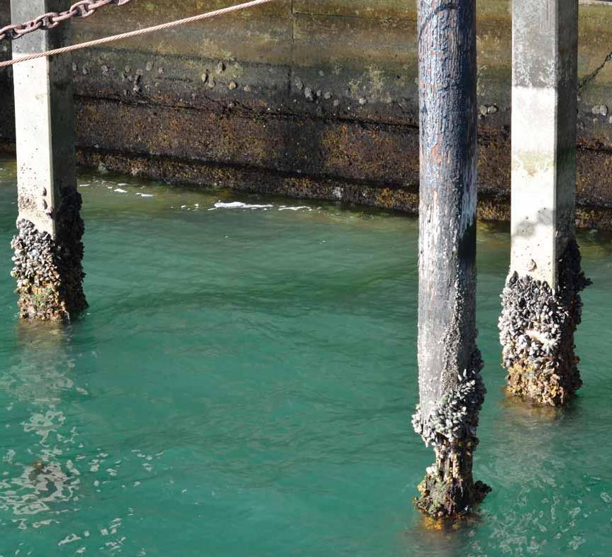
With 40+ years of proven performance, our FX-70® Structural Repair and Protection System repairs concrete, steel and wood piles and protects against Protection System repairs concrete, steel and wood piles and protects against further deterioration. From custom-manufactured fiberglass jackets to further deterioration. From custom-manufactured fiberglass jackets to underwater epoxies and cementitious grouts, we have cost-effective, practical, underwater epoxies and cementitious grouts, we have cost-effective, practical, long-term solutions for your repair projects. long-term solutions for your repair projects. Since 1956, Simpson Strong-Tie has brought innovative solutions to customers’ Since 1956, Simpson Strong-Tie has brought innovative solutions to customers’ construction challenges. To learn more about our products that repair, protect construction challenges. To learn more about our products that repair, protect and strengthen, call us at 800-999-5099 or visit and strengthen, call us at 800-999-5099 or visit strongtie.com/rps.
Watch the FX-70® Pile Repair Cyclic Testing at strongtie.com/videolibrary and subscribe to our YouTube Channel at youtube.com/strongtie and subscribe to our YouTube Channel at youtube.com/strongtie
Building a Strong Future
By Jun Fei, P.E.
University of Kansas West Campus Structural Testing Laboratory
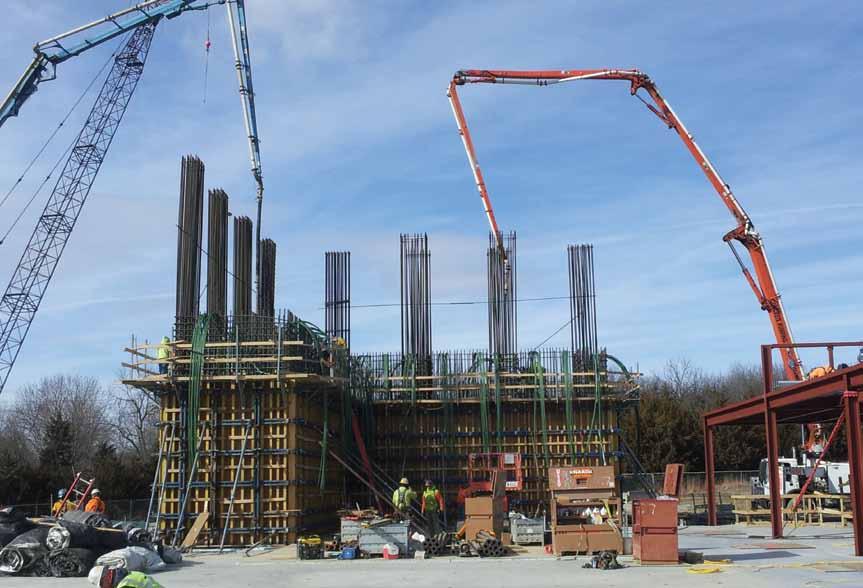
With an eye toward innovation and student collaboration, the University of Kansas (KU) School of Engineering wanted to significantly expand its scope of structural research. Opened in 2014, the Structural Testing Laboratory (Figure 1), located on the KU West Campus in Lawrence, is laying the groundwork for future innovation and offers one of the most advanced structural testing facilities in higher education. The 26,000-square-foot building is equipped with state-of-the-art instruments to accommodate full-scale systems and components and provide workshop spaces for student design and competition projects, as well as fabrication and machine shops.
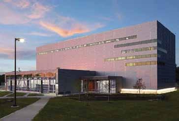
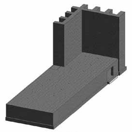
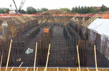
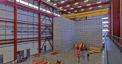
Figure 6. Test area with overhead cranes. The principal element of the facility consists of a strong floor and strong wall system (Figure 2) constructed of cast-in-place concrete with a specified strength of 5,000 psi at 28 days. The strong floor, which provides 7,000 square feet of test area, is a 3-foot-thick slab supported by basement walls. A heavily reinforced mat slab (Figure 3) was designed as the foundation to support the strong wall and strong floor system. As a result, the strong floor, basement walls, and mat foundation slab form a four-cell box girder that is 15 feet deep, 48 feet wide and 145 feet long. To secure test specimens, the strong floor has vertical through-slab tie-down holes (anchor points) spaced at 3 feet on center in both directions (Figure 4), each tie designed for an allowable vertical load of 100,000 pounds in tension or compression. The 40-foot-tall strong wall – also called a reaction wall – is 4 feet thick and located at the east end of the strong floor, backed by 8-foot-deep buttresses spaced every 12 feet. Self-consolidating concrete and ASTM A416 Grade 270 post-tensioning tendons were used for both the wall and the buttresses (Figure 5), and the vertical reinforcing bars are ASTM A615 Grade 75. The strong wall is perforated with horizontal tie-down holes (anchor points), on the same grid as the strong floor, for the wall-mounted hydraulic actuators to apply lateral forces to the test specimens. The strong wall has an “L-shaped” profile, with two equal legs, to provide versatility for bi-directional testing. Each leg of the wall has a reaction area that is 36 feet long by 40 feet tall. The strong wall design provides an allowable lateral testing force of 880,000 pounds at each leg simultaneously, and thus an overall allowable lateral testing force of 1.76 million pounds. The strong floor and strong wall test area is equipped with two 20-ton capacity overhead cranes (Figure 6 ) to handle large and/or heavy test specimens, as well as hydraulic actuators and other equipment inside the laboratory.
Figure 2. Strong floor and strong wall ISO. Courtesy of Burns & McDonnell. Figure 3. Concrete mat foundation.
The key engineering challenge of the project was the strong wall, which is a performance-driven, highly customized element. From the design perspective, at the very earliest stage of the project, the structural team had numerous meetings with the end-user groups including the Dean of the School of Engineering, professors, researchers, and graduate students. It was critical to learn from these groups their expectations, needs, and intentions regarding the strong wall. Information from these meetings set the design goals for the structural team to achieve in a constructible and economical way. Because of the tremendous test forces to be placed on the strong wall, the design team and KU were concerned about potential cracking in the concrete surface. To address this concern, the design team performed concrete stress analysis utilizing computer software to determine the magnitude of the calculated stresses under various load combinations that were representative of different tests that could be performed. This identified “hot spots,” where the calculated tensile stress was greater than the allowable value. The next challenge presented to the structural engineer was how to reduce the high tensile stresses in a constructible manner. The solution was to place post-tensioning tendons in the vertical direction of the wall to introduce compressive forces. Once the design was complete, the strong wall also presented challenges from the construction perspective. The design criteria required a high-level concrete surface finish to satisfy both aesthetic and performance requirements. After further discussions with the construction contractor, the Kansas City office of Turner Construction, the team decided to utilize self-consolidating concrete for the wall. To ensure
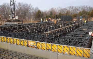
Figure 4. Strong floor with tie-down sleeves. achievement of the desired concrete finishes and structural qualities, Turner built a large-scale mock-up of the strong wall on the site and then cut it open to determine how the self-consolidating concrete had performed. The results passed inspections with flying colors. Turner also developed a robust system of formwork that was adequate to hold the fresh concrete in place. The $14.5-million facility has opened to positive reviews on campus. Research commitments are building, and KU’s structural labs will be fully committed by the time of this article’s publication according to Michael Branicky, the Dean of KU School of Engineering.▪
Jun Fei, P.E. (jfei@burnsmcd.com), is a senior structural engineer in the Global Facilities Group at Burns & McDonnell in Kansas City, Missouri.
Project Team
Owner: The University of Kansas Structural Engineer of Record: Burns & McDonnell Prime Contract Holder: Treanor Arch. Architect of Record: Burns & McDonnell Construction Contractor: Turner
Construction Company, Kansas City


