14 minute read
monongahela river Bridge


Historic structures
significant structures of the past
After the success of Wendell Bollman’s truss at Harpers Ferry and elsewhere, Benjamin Latrobe encouraged Albert Fink to design a longer span iron bridge that he could use on his major river crossings between Harpers Ferry and the Ohio River. Fink (STRUCTURE, May 2006), after obtaining his engineering degree in Germany, immigrated to the United States in late spring 1849. He went to work on the B&O Railroad working with Wendel Bollman (STRUCTURE, February 2006) and Latrobe. Fink, after reviewing Bollman’s bridge, believed he could improve on that design. His first effort for a cast and wrought iron bridge was similar in appearance and details to Bollman’s. He prepared his drawings, and he and Latrobe decided to enter it into a design competition held in Boston. He wrote in his diary, “The competition is over. We who have brought designs were handsomely entertained. I did not win. Latrobe has taken my defeat greatly to heart. I was surprised when he told me politics influenced the decision.” Monongahela River Bridge Hungerford, in his history of the B&O, wrote a description of Fink’s design method: “The rule By Frank Griggs, Jr., Dist. M. ASCE, of thumb methods that were used in the creation D. Eng., P.E., P.L.S. of so many early iron and wooden bridges were hardly to be trusted in the making of an all iron one. So Fink would go to work with pieces of tin and wires, building up trusses in miniature, testing strains and stresses carefully upon these, and from such experiments making his deduction and formulas for the construction of full sized spans.” Based upon this work, Latrobe gave him the project of building a three span bridge across the Monongahela at Fairmont, Virginia (later West Virginia) in 1852. He thought, as did Fink, that Dr. Griggs specializes in the Fink’s plan was better suited than Bollman’s for restoration of historic bridges, longer spans, and he adopted it for sites requiring having restored many 19th Century such spans. This was Fink’s first bridge and it was cast and wrought iron bridges. He was formerly Director of Historic Bridge Programs for Clough, Harbour & Associates LLP in Albany, NY, and is now an independent Consulting Engineer. Dr. Griggs can be reached at fgriggs@nycap.rr.com.
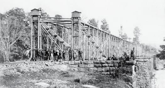
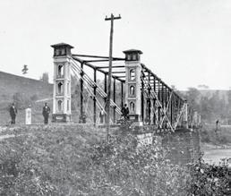
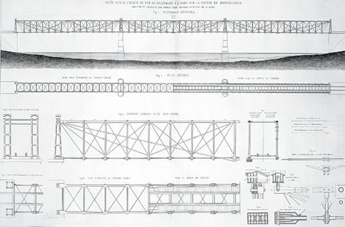
Monongahela Bridge 1865 – 1887, note skew. Courtesy of HAER.
the longest span iron bridge in the United States at that time, surpassing Bollman’s span length of 124 feet by 65%. A four span wooden trestle was built first, to aid in construction and to serve as a temporary crossing. Construction on the masonry piers began in 1850 but was not finished until the end of 1851. Fink’s plan, which may have preceded Bollman’s according to a family biography, consisted of three 205-foot long pinned spans with cast iron upper chords, verticals, lower chord and towers, and wrought iron diagonals and bracing. Many of the details were similar to Bollman’s, since they were both built at the B&O shops. The main difference between Bollman’s and Fink’s trusses was that all of Fink’s long paired diagonals were of equal length. The bridge was 16 feet wide for a single track, had a depth of 20 feet and was built on a skew. It opened in 1852. When building it he wrote home to Germany telling his fiancée Mimi, “I am in complete charge of the building of our bridge across the Monongahela River, a project which will cost $120,000…I cannot help but think often of my colleagues in Germany who
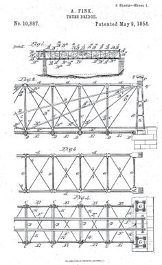


Fink Through Truss Patent Drawing, like Monongahela River Bridge.
are still sitting with their feet under a desk waiting for some opening…” The difference between a Bollman and Fink Truss was covered in a newspaper article in the Republic and Times newspaper of Buffalo, New York. They wrote, “Mr. Bollman’s plan is entirely different in principle from that of the iron bridge over the canal, near the Erie Depot. This bridge is the Bollman plan. The tension rods are of unequal length, so that for the same expansion there is a different increase in the lengths of the rods sustaining the same point, causing the longer rods to become very loose. This is not the case with the Fink patent – the one selected by Mr. Latrobe. In this bridge, the tension rods are of equal length and, expanding and contracting together, they are kept in proper adjustment at all times. The manner of joining the supporting rods to the uprights upon the piers is also entirely different. This connection is so arranged in the Fink patent that the whole bridge truss is allowed to move freely, thus preventing the strains to which the injurious effects of expansion and contraction are attributable. These two circumstances are sufficient to make up the difference between a very good and a very bad bridge; and we therefore warn all not to confound the two.” In other words, the Fink is the good truss and the Bollman the very bad truss. On May 9, 1854, Fink received patent #10,887 for a Truss Bridge. It was for both a deck truss and a through truss like he built over the Monongahela River. He claimed, “I do not claim as new, the manner in which the central post is supported; nor do I claim the combination of a series of triangular bracings, in such a manner, that one system of triangles is supported by and dependent on the other, merely, as I am aware that this has been done before, both in trusses for bridges and roofs. But what I do claim as of my own invention, and as different from any other method of bracing and strengthening bridge trusses heretofore known, is – The method of combining the different systems of triangular bracings, above described, so that a weight coming on one of the systems of the truss, is not only transferred over one or more other systems, before it is carried back to the abutments; but the foot of the post in each triangle, being unconnected with

THE INDUSTRY LEADER IN SEISMIC AND WIND SOLUTIONS IS NOW EVEN STRONGER.
Nearly two decades ago Hardy Frames created the fi rst steel shear wall system and revolutionized the residential building industry. Today the name Hardy Frame® remains the most trusted name in seismic and wind solutions.
As part of MiTek’s new Builder Products Division, the Hardy Frame® Shear Wall System, along with USP Structural Connectors® and the Z4 Tie-Down System, can offer you better, stronger structural solutions.
Contact us today and let us create the right solution for you.
hardyframe.com/solutions 800 754.3030
Hardy Frame®
HFX-Series Panel
Hardy Frame®
Moment Frame
Better Technology. Better Building.SM
www.mitekbuilderproducts.com/solutions
the tension rods of the other triangular bracings, can settle vertically, as well as move to the side; so that the tension rods of each system of the triangular bracings will be strained equally, when the bridge settles under a superincumbent weight.
This would not be the case, if the foot of the post in the 2d system of triangular bracings rested on the tension chord of the post, in the first system, as heretofore used; and herein consists my improvement, for which I ask Letters Patent.” He also noted “the sinking of a portion of the truss by a superincumbent weight, or by changes in the condition of the material used in construction from the effect of temperature, will not cause the several parts of the truss to deviate from their mutual adjustments…” The “first system” he is referring to is the Bollman Truss, which had been patented two years earlier and was being built on the eastern segment of the B&O. After its opening in 1852, it lasted until 1863 when it was burned by the Confederates during the Civil War. It was replaced with a wooden trestle that lasted until 1865 when two spans were replaced with Fink Trusses. In 1868, the third span was replaced. The trusses were similar to the original, but the new towers were built in an Italianate design. The bridge was replaced in 1887 and again in 1912 when steel Warren Trusses were used. At the time of its construction, it was the longest iron bridge built in the United States with a total length of 615 feet. It, along with Bollman’s, led to a greater trust in the use of iron for railroad bridges. For total length it was only exceeded by Robert Stephenson’s Tubular Bridge in Wales. It received worldwide recognition after
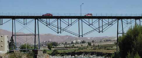
Rio Chili Bridge. Courtesy of Mark Yashinsky. its construction. It was never adopted overseas or by other American bridge builders, with the notable exception of C. Shaler Smith and the Baltimore Bridge Company.
Fink left the B&O in 1857 to work on the Louisville and Nashville (L&N) railroad. One of his first efforts was the construction of the Green River Bridge near Mammoth Kentucky. It was a five span deck bridge with the three middle spans being 208 feet and the two outer spans 181 feet. The deck level was 115 feet above the water level in the river. The bridge opened in 1859, but during the Civil War the Confederates blew up the two southerly spans. After the Civil War, the wooden High Bridge over the Appomattox River was rebuilt in 1869 with 21 Fink deck trusses at an elevation of up to 160 feet. His largest bridge was his Louisville, Kentucky Bridge over the Ohio River that opened in 1870. It was the longest bridge (5,250 feet) in the world at the time. It consisted of 25 conventional Fink deck trusses with spans ranging from 50 feet to 245 feet - 5 inches, and two major long-span through trusses of 370 feet and 400 feet, plus a side mounted swing span over the Louisville and Portland Canal. His and Bollman’s trusses were generally built between the early 1850s up until the post Civil War period, when Whipple Double Intersection Trusses in cast and wrought iron, and later steel, became the standard railroad trusses until the end of the century. Only two of Fink’s bridges survive in the United States. The first was constructed in approximately 1870 as a railroad bridge and converted to vehicular use in 1893. The truss was moved to a park in Lynchburg, Virginia in 1985, where it is now used as a footbridge. It was designated as a National Historic Civil Engineering Landmark in 1985. A 108-foot single span through truss was originally built by the Smith & Latrobe Company in 1869 as one of three spans to cross the Tuscarawas River at Canal Dover, Ohio. Smith was a protégé of Albert Fink, working with him on the L&N Railroad. It utilized Phoenix wrought iron compression members and cast iron junction blocks, and was a modified Fink Truss, lacking four verticals. It was replaced with a new bridge in 1905 and moved to Zoarville Station, Ohio, where it was abandoned in place in 1940. It was restored and rebuilt at this site across the Conotton River in 2007. There it serves as a bicycle and pedestrian path that connects with the Ohio and Erie Towpath Trail. One Fink truss remains in Arequipa, Peru crossing Rio Chili. It originally carried a railroad, but now carries a single line of automobile traffic. Mark Yashinsky, a California Bridge Engineer, indicates that the locals say the bridge was built by Gustav Eiffel, which is unlikely. The Baltimore Bridge Company was building bridges like the Verrugas Viaduct in Peru at the time. It was erected by Leffert L. Buck, so it is likely that the entire Arequipa Viaduct was built by the Baltimore Bridge Company. The towers are supported by Phoenix Columns, and the truss compression members are also Phoenix shapes.▪


a definitive listing of wood product manufacturers and their product lines
American Wood Council
Phone: 202-463-2766 Email: lbalsavage@awc.org Web: www.awc.org Product: 2012 ASD/LRFD Manual for Engineered Wood Construction Description: Design information for structural lumber, glued laminated timber, structural-use panels, shear walls and diaphragms, poles and piles, I-joists, structural composite lumber and over 40 details are included in the chapter on connections. This publication is a free download from the AWC website.
Anthony Forest Products Company
Phone: 870-918-3414 Email: kdrake@anthonyforest.com Web: www.anthonyforest.com Product: Power Beam®, Power Column®, PRG® Description: These are a collection of Anthony Forest Products Power Products.
APA-The Engineered Wood Association
Phone: 253-565-6600 Email: help@apawood.org Web: www.apawood.org Product: APA Description: Supports the industry in the manufacture and use of structural wood products of exceptional strength, versatility, and reliability. APA offers a wealth of educational and technical tools, including over 500 publications, CAD details, and wall bracing calculator. APA’s Designers Circle website offers continuing education, design news, and calendar of events.
Bentley Systems
Phone: 800-236-8539 Email: structural@bentley.com Web: www.bentley.com Product: RAM Elements Description: For analysis and design of almost any type of structure or structural component,complete with sophisticated design tools to help you with your everyday analysis and design needs.
Laminated Concepts Inc.
Phone: 607-562-8110 Email: matt@lamcon.com Web: www.lamcon.com Product: Glued Laminated Timber Bridges Description: Supplier of quality engineered glued laminated timber products for the transportation industry including pedestrian and vehicular bridge structures. RedBuilt
Phone: 208-364-1322 Email: csprung@redbuilt.com Web: www.redbuilt.com Product: Red-I™ I-Joists Description: Manufactured using high-quality, engineered wood – including LVL flanges and RedBuilt’s proprietary OSB web. Dimensional stability helps resist the warping, twisting, and shrinking that can lead to squeaky floors. Strong yet lightweight and include a wide range of sizes and depths in lengths up to 80 feet.
Product: RedLam™ LVL Description: Can be used as main carrying beams, flush beams, headers and wall framing. The RedLam LVL manufacturing process removes and disperses the natural defects inherent in wood and produces a product that is strong, dimensionally stable, and reliable.
Simpson Strong-Tie®
Phone: 800-999-5099 Email: web@strongtie.com Web: www.strongtie.com Product: Simpson Strong-Tie Strong-Wall® SB Shearwall Description: Shearwall is prefabricated and trimmable, and provides enhanced design flexibility and greater lateral-force-resistance performance. In areas susceptible to earthquakes or high winds, it provides structural support comparable to steel shearwalls in narrow panel widths. It installs easily to support two-story structures, garage portals and large openings. Product: Simpson Strong-Tie DU/DHU/DHUTF Drywall Hangers Description: Designed for wood-frame, multistory, Type III construction, the new DU/DHU/DHUTF drywall hangers carry joist floor loads to a wood stud wall through two layers of 5/8-inch drywall. These hangers install after the drywall is in place and are available in sizes that accommodate most joists, including I-joists and trusses.
TECO
Phone: 855-266-8326 Email: steve.winistorfer@tecotested.com Web: www.tecotested.com Product: Certification and Testing of EWP’s Description: An independent, third-party certification and testing agency for manufacturers of structural and non-structural engineered wood products (like plywood, OSB, LVL, MDF, particleboard, rimboard) and structural adhesives. Laboratories in Wisconsin and Oregon, and clients in more than a dozen countries. TECO TESTED® – It’s more than a stamp!
All Resource Guide forms for the 2015 Editorial Calendar are now available on the website, www.STRUCTUREmag.org. Listings are provided as a courtesy. STRUCTURE® magazine is not responsible for errors. Tekla
Phone: 770-426-5105 Email: kristine.plemmons@tekla.com Web: www.tekla.com Product: Tekla Structures Description: Can be used for wood framing: True BIM model of wood framing, parametric components allow for easy creation and design change, easily add or move doors and windows, library of industry standard wood connections included, clash checking functionality to eliminate change orders, easily customizable to suit any job requirements. Product: Tedds Description: Using Tedds, you can design a range of wood elements, including: beams (single span, multi-span and cantilever); wood columns; sawn lumber, engineered wood, glulam and flitch options; shear walls (multiple openings, segmented or perforated); connections (bolted, screwed, nailed, wood/wood and wood/steel); produce detailed and transparent documentation.
Western Wood Structures, Inc.
Phone: 800-547-5411 Email: dougt@westernwoodstructures.com Web: www.westernwoodstructures.com Product: Curved Glulam Description: Why choose us to design and supply your engineered timber structure? Gluelaminated timber can be manufactured into many configurations, including curved members and structural components, allowing wide latitude in its design. Our in-house engineering allows us to offer custom-designed wood products using a variety of timber choices. Call us today!
Weyerhaeuser
Phone: 888-453-8358 Email: wood@weyerhaeuser.com Web: www.woodbywy.com Product: Trus Joist® Engineered Lumber Products Description: A range of solutions for designing and building high-performance structural frames, providing longer lengths, easier installation, higher span values, better strength-to-weight ratios, and faster cycle times. Products include TJI® Joists, TimberStrand® LSL, Microllam® LVL, and Parallam® PSL, along with design, sizing, and estimating software.
WoodWorks Software
Phone: 800-844-1275 Email: sales@woodworks-software.com Web: www.woodworks-software.com Product: WoodWorks Design Office Suite Description: Conforms to the IBC 2012, ASCE7-10, NDS 2012, SDPWS 2008; SHEARWALLS: designs perforated and segmented shearwalls; generates loads; rigid and flexible diaphragm distribution methods. SIZER: designs beams, columns, studs, joists up to 6 stories; automatic load patterning. CONNECTIONS: Wood to: wood, steel or concrete.


