
131 minute read
Advertiser Index
Aegis Metal Framing ............................. 26 Bentley Systems, Inc. ............................. 51 Canadian Wood Council ....................... 53 Computers & Structures, Inc. ............... 68 CSC, Inc. ................................................ 3 Design Data .......................................... 47 Devco .................................................... 46 Ecospan Composite Floor System ......... 29 Fyfe ....................................................... 21 GT STRUDL........................................ 13 Th e IAPMO Group ............................... 31 Integrated Engineering Software, Inc. .... 48 KPFF Consulting Engineers .................. 43 NCEES ................................................. 41 Nemetschek Scia ................................... 44 New Millennium Building Systems ....... 11 Nucor Vulcraft Group ........................... 55 Powers Fasteners, Inc. .............................. 2 RISA Technologies ................................ 67 S-Frame Software, Inc. ............................ 4 SidePlate Systems, Inc. .......................... 39 Simpson Strong-Tie............................... 19 Struct. Eng. Assoc. of Illinois ................. 58 StructurePoint ....................................... 49 Struware, Inc. ........................................ 40 Taylor Devices, Inc. ............................... 15 USP Structural Connectors ................... 57 Wood Products Council ........................ 33
New Resource

The STRUCTURE magazine website (www.STRUCTUREmag.org) now includes a “Continuing Columns” page that features past InFocus, Structural Forum, Great Achievements, Quality Assurance Corner, and Just the FAQs articles. The 11-part Antiquated Structural Systems Series is also compiled there, and its author, D. Matthew Stuart, has added an “illustrated dictionary” as an online-only supplement.
S T R U C T U R E ®
A Joint Publication of NCSEA | CASE | SEI
Special Section: Engineering Software
August 2012 Steel ON THE COVER Th is diagonal strap braced wall with 4:1 aspect ratio is part of August’s Codes & Standards column (page 12) on designing cold-formed steel framed lateral force resisting systems. Th is article discusses the history of the code provisions, some of the design considerations unique to CFS framed lateral force resisting systems, and resources available to aid designers. Courtesy of AISI & McGill University.
editorial Board
Chair
Jon A. Schmidt, P.E., SECB
Burns & McDonnell, Kansas City, MO chair@structuremag.org
Craig E. Barnes, P.E., SECB
CBI Consulting, Inc., Boston, MA
Richard Hess, S.E., SECB
Hess Engineering Inc., Los Alamitos, CA
Mark W. Holmberg, P.E.
Heath & Lineback Engineers, Inc., Marietta, GA
Roger A. LaBoube, Ph.D., P.E.
CCFSS, Rolla, MO
Brian J. Leshko, P.E.
HDR Engineering, Inc., Pittsburgh, PA Brian W. Miller
Davis, CA
Mike C. Mota, Ph.D., P.E.
CRSI, Williamstown, NJ
Evans Mountzouris, P.E.
The DiSalvo Ericson Group, Ridgefi eld, CT
Greg Schindler, P.E., S.E.
KPFF Consulting Engineers, Seattle, WA
Stephen P. Schneider, Ph.D., P.E., S.E.
BergerABAM, Vancouver, WA
Advertising Account MAnAger
Interactive Sales Associates Chuck Minor Dick Railton
Eastern Sales Western Sales 847-854-1666 951-587-2982 sales@STRUCTUREmag.org
editoriAL stAFF
Executive Editor Jeanne Vogelzang, JD, CAE
execdir@ncsea.com
Editor Christine M. Sloat, P.E.
publisher@STRUCTUREmag.org
Associate Editor Nikki Alger
publisher@STRUCTUREmag.org
Graphic Designer Rob Fullmer
graphics@STRUCTUREmag.org Web Developer William Radig
webmaster@STRUCTUREmag.org
STRUCTURE® (Volume 19, Number 8). ISSN 1536-4283. Publications Agreement No. 40675118. Owned by the National Council of Structural Engineers Associations and published in cooperation with CASE and SEI monthly by C3 Ink. The publication is distributed free of charge to members of NCSEA, CASE and SEI; the non-member subscription rate is $65/yr domestic; $35/yr student; $90/yr Canada; $125/yr foreign. For change of address or duplicate copies, contact your member organization(s). Any opinions expressed in STRUCTURE magazine are those of the author(s) and do not necessarily refl ect the views of NCSEA, CASE, SEI, C3 Ink, or the STRUCTURE Editorial Board.
STRUCTURE® is a registered trademark of National Council of Structural Engineers Associations (NCSEA). Articles may not be reproduced in whole or in part without the written permission of the publisher.
www.ncsea.com
C3 Ink, Publishers
A Division of Copper Creek Companies, Inc. 148 Vine St., Reedsburg WI 53959 P-608-524-1397 F-608-524-4432 publisher@STRUCTUREmag.org
Visit STRUCTURE magazine on-line at www.structuremag.org Visit STRUCTURE magazine on-line at www.structuremag.org Visit STRUCTURE magazine online at www.structuremag.org
editorial new trends, new techniques and current industry issues Important Meeting for All Practicing Structural Engineers
By James O. Malley, S.E., P.E., SECB Vice President of Engineering, Degenkolb Engineers, and NCSEA Immediate Past President
The 2012 NCSEA Annual Conference will be held in St. Louis from October 3 – 6. The theme will be “The Spirit of St. Louis – Design Trends for the Future”. I strongly encourage all practicing structural engineers to attend, for an outstanding opportunity to learn from and interact with leaders of the structural engineering profession. The conference will kick-off on the morning of Thursday, October 4th with a series of talks on hot topics in the code and standards development arena. After an overview talk on the main changes in the 2012 IBC by NCSEA Code Advisory Committee (CAC) Chair Ron Hamburger, Wind Subcommittee Chair Don Scott will provide details on the newly adopted ASCE 7-10 wind provisions and insight into the likely direction of the next edition of the ASCE 7. Seismic Subcommittee Chair Kevin Moore will tackle how to apply the ACI 318 Appendix D provisions on anchorage to concrete in seismic applications, a controversial topic that can be misinterpreted by practicing engineers. This will be followed up by a summary of the implications of the new provisions for strengthbased masonry design by General Engineering Subcommittee Chair Ed Huston. Evaluation Services Subcommittee Chair Bill Warren and ICC Evaluation Services Director of Engineering Jim Collins will wrap up the session by describing the ICC Evaluation Services program for approving new structural products and how it affects your engineering practice. Once we’ve all been updated on the latest important code developments, we will be further enlightened by keynote speaker Lawrence (“Larry”) Griffis of Walter P Moore and Associates. Larry, one of the world’s pre-eminent structural engineers, will speak on Structural Engineering Practice – Instilling “A Culture of Discipline”. His talk will focus on the changes to our professional practice that now require structural engineers to not only have technical skills, but also be trained to collaborate, communicate, and document their every move. To achieve success, or even survive, in this challenging but rewarding profession, engineers must learn and practice a certain culture of discipline. Thursday’s afternoon session will begin by focusing on the latest developments related to snow loading provisions of ASCE7-10. Dr. Michael O’Rourke will cover the basis for the changes to snow provisions. This will be followed by discussion from Joe Zona on lessons learned from snow-induced collapse of buildings last winter from the heavy snowfall in New England. Joe’s emphasis will be on the primary factors that led to the collapses, including the performance of buildings constructed using current ASCE 7 provisions for snow loading. Thursday’s program will wrap up with a presentation on the devastating effects of the 2011 Joplin, Missouri tornado by Randall Bernhardt and Malcolm Carter, who participated in an effort by SEAKM to investigate the performance of some of the building types damaged by the tornado. This investigation found commonalities in damage patterns, regardless of building type, and developed recommendations for building code updates and further research. On Friday morning, the focus will shift to updates on emerging tools and technology for seismic design. Jon Heintz of the Applied Technology Council (ATC) will present key findings, conclusions, and discoveries from recently completed and ongoing ATC projects addressing R factors, tall building design, ground motion selection, soil-foundation-structure interaction, and soft-story building evaluation and retrofit. Ron Hamburger will follow up with a detailed overview of the ATC-58 project report, Seismic Performance Assessment of Buildings (FEMA P-58), the next-generation of performance-based methods that estimates the consequences of seismic damage on individual buildings in terms of casualties, repair costs, and downtime. The technical sessions on Friday afternoon will be presented by NCSEA Publications Chair, Dr. Tim Mays, who will present material from two recent NCSEA-generated design guides that should be on the shelves of all practicing engineers, as well as two soon-to-be-published design guides that many practicing structural engineers have been seeking. Tim’s presentation on the first two guides, titled Guide to the Design of Diaphragms, Chords and Collectors and Guide to the Design of Out-of-Plane Wall Anchorage, will focus on example problems and appropriate hand and computer modeling techniques necessary to design these elements. Tim’s presentation on the second two guides, titled Guide to the Design of Building Serviceability and Guide to the Design of Foundation Systems, will focus on all areas of serviceability, including practical example problems, 2012 IBC Chapter 18, and ASCE/SEI 7-10. Tim will conclude with an overview of the topics of other upcoming NCSEA design guides. While I hope you agree that this is an outstanding lineup that will provide you with valuable information and new tools to improve your practice, the conference has much more to offer. On Wednesday, October, 3rd, the conference will host ICC Evaluation Services hearings, NCSEA committee meetings, exhibitor and vendor presentations and a tour of the nearby AZZ Galvanizing plant, all at no additional cost to Conference attendees. The annual meeting of NCSEA’s 43 Member Organizations will occur from 8 a.m. – 9:45 a.m. (Member Organization reports) on Friday and from 8 a.m. thru lunch on Saturday. Social events include a Wednesday evening reception hosted by the Structural Engineering Certification Board (SECB), a Thursday evening Exhibitor Reception, and a Friday evening Awards Banquet, presenting the NCSEA Excellence in Structural Engineering awards and honoring engineers who have made outstanding contributions to the structural engineering profession. Also note that for the first time, Young Members (defined as members age 35 and younger) will be offered a special 25% discount on Conference registration fees. St. Louis was selected for this year’s Conference because of its central location, as well as reasonable air fares and hotel rates ($102/night plus tax). I hope that you will agree that the outstanding technical program, as well as all of the other activities at the conference and the reasonable price point, make this year’s annual conference a terrific value. For more information and to register, please visit NCSEA Conferences and Institutes at www.ncsea.com. I hope that all of you will meet me in St. Louis!▪
Building Blocks
updates and information on structural materials
Brace Yourself!
Novel Uses for the Buckling Restrained Brace
By Kimberley Robinson, S.E.
Kimberley Robinson, S.E. is the chief engineer with Star Seismic, Park City, Utah. Kimberly can be reached at KimR@StarSeismic.net. The Buckling Restrained Brace (BRB) was introduced in the United States in the late 1990s and since then has been used in nearly 500 structures. The Buckling Restrained Braced Frame (BRBF), the lateral-load resisting system that uses the brace as an integral component, has been codified since 2005. However, due to the attributes of buckling restrained braces, many projects use the BRB in unique ways that differ from the standard BRBF concentrically braced frame. The BRB brace consists of two main parts: the central steel core and the surrounding outer casing assembly. The brace’s main load-carrying element, the core, is encased in an outer assembly that confines the core and provides stability to the system, to the point that the core will yield in compression. This creates a brace with a strength that is nearly the same in both tension and compression and is designed not to buckle. Some of the attributes of the BRB brace are that the yield load, expected strain-hardened capacity and elastic stiffness can all be defined and controlled. The symmetrical capacity of tension vs. compression allows BRB braces to be used in single-diagonal configurations without penalty. And the system harnesses the ductility of steel to provide sustained, repeatable performance and energy absorption. Due in part to these features, BRBs have been used in or proposed for a variety of applications, including bridges, civil structures, horizontal diaphragm elements, highrise outrigger frames, externally anchored braces, wind towers and many other
Single Brace Retrofit
Rutherford & Chekene, a structural engineering consulting firm in San Francisco, was presented with a unique challenge in the seismic evaluation and retrofitting of a historic steel and concrete structure. This two-story electrical substation was built in the early 1920s and remains an important link in the region’s electrical power network. Renovations performed over the years had removed the lower portion of one of the concrete walls. The resulting structure was not adequate to meet the owner’s seismic performance objectives. Retrofit options were limited. Replacement of the concrete wall that had been removed was not an option, as critical communications equipment that could not be moved had been placed in that area. Bracing on the exterior of the structure was not possible because of the historic character of the building and the presence of high-voltage buried conduits. A single brace could be allowed in the high-bay room adjacent to the area where the wall had been removed. A buckling restrained brace was selected as it was able to support both tension and compression loads while maintaining the required strength and ductility (Figure 1). In addition, the brace strength could be “tuned” to avoid overloading collectors and floor diaphragms, and to match the strength of the remaining walls and reduce the possible plan-torsion of the structure under strong earthquake shaking. A new collector and foundation was provided to complete this portion of the retrofit.
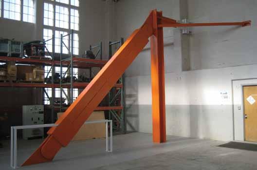
Figure 1: Single BRB brace project. Courtesy of Rutherford & Chekene.
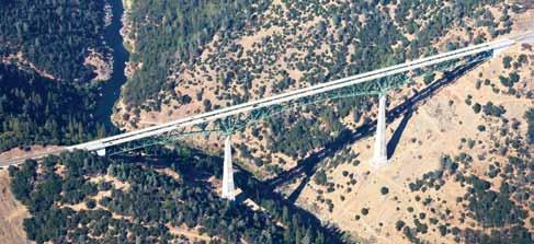
Figure 2: Schematic of the One Rincon outrigger system. Courtesy of Magnusson Klemencic Associates. Figure 3: Foresthill Road Bridge. Courtesy of Todd Quam, DigitalSky Imaging.
Figure 4: Casad Dam and intake structure. Courtesy of Star Seismic.

Highrise Outrigger System
The One Rincon Hill South Tower is a 56-story, 578-foot tall residential structure. It is located next to the western approach of the San Francisco – Oakland Bay Bridge. In the heart of one of the most seismically active regions in the US, the design was also governed by considerations from powerful Pacific winds due to its prominent location on the skyline. The design of the structure includes a rectangular concrete core for the seismic and wind forces. The length of the core in one direction was sufficient to resist overturning demands, but the other was too narrow to adequately control building sway. The design team at Seattle based Magnusson Klemencic Associates decided to incorporate an outrigger system into the structure to bolster the stiffness in the core’s narrow dimension, much the same as the use of ski poles can stabilize a skier. The outrigger system served to reach out to the large concrete outrigger columns to engage them for resistance to overturning at four levels of the structure (Figure 2). Buckling restrained braces allowed the design team to limit the amount of load that would be delivered to the outrigger columns while controlling the stiffness and response of the building. In addition, a large tank at the top of the building holding up to 50,000 gallons of water is used for two purposes: as a tuned liquid damper to counter the sway from wind forces and as a reservoir for firefighting purposes.
Bridge
The tallest bridge in California, the Foresthill Road Bridge, was determined to be in need of seismic retrofitting. This famous bridge, spanning the North Fork Canyon of the American River, was built in the early 1970s and measures 2,428 feet from one side to the other. At more than 730 feet above the river, it is the fourth highest bridge in the United States and the ninth highest bridge in the world (Figure 3). The bridge is a truss bridge and provides the primary link between the towns of Auburn and Foresthill, California. As part of the retrofit, the bridge deck is being widened to maintain traffic flow while the retrofit is taking place. The design team at Quincy Engineering in Sacramento, CA, along with the Placer County Department of Public Works, completed the seismic evaluation and developed alternate retrofit solutions. The project included a very detailed project specific design criteria that was reviewed by a Technical Peer Review Panel and had very specific performance measures. There were multiple sets of ground motions that were based on a 1.0g peak ground acceleration. Through all of the detailed analysis, it was determined that BRBs achieved the performance objectives and allowed for repairable damage after a maximum credible event. One important design objective was to limit the seismic forces on the longitudinal abutment anchors of the bridge, both to protect the anchorages themselves and protect the surrounding truss members, by confining the inelastic demands to sacrificial link-plates that will fail at a prescribed strain and then allow the BRB’s to engage. The link plates can easily be replaced and, once the BRBs begin yielding, they will perform in a stable inelastic, ductile behavior which allows large energy dissipation. The final configuration, with BRBs located longitudinally at the truss bottom chord connections to the abutments, was an effective and economical way to meet the design objectives.
Civil Structure
Casad Dam is a concrete gravity arch dam built in the 1950s that includes an integral intake tower located on the upstream face at the center of the dam. The intake tower was not adequate to support the anticipated seismic demands, where the peak ground acceleration was increased due to the proximity of the Seattle fault and new research into the magnitude of potential events. A retrofit scheme was needed for the intake tower that would have minimal impact on the normal operation of the dam, would have minimal underwater work, and could be done with minimal expense. The design team at Hatch Associates Consultants, Inc. in Seattle, WA investigated several options and found that bracing the tower back to the dam best met their key objectives for the retrofit, rather than strengthening the tower at its base. However,

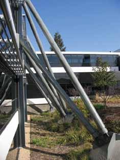
Figure 5: Horizontal BRB braces to buttress frame. Courtesy of Dave McCormick, SGH. Figure 6: Externally anchored bracing. Courtesy of Mitsui & Co. (U.S.A.), Inc.

the arch dam required protection by limiting the brace forces. Viscous dampers and buckling restrained braces were considered and, after detailed simulations, stainless steel buckling restrained braces with a yielding steel core were selected (Figure 4, page 9). The project successfully met diverse functional objectives that included preventing tower collapse under a maximum credible earthquake with a 0.78g peak ground acceleration, meeting low maintenance requirements while providing high reliability, and ensuring that there were no environmental or water quality impacts.
Horizontal Buttresses
Retrofitting of structures can create particularly difficult design challenges. When the structure being retrofitted is congested with piping and equipment that must stay in place, the level of complexity is increased. When the structure is a manufacturing facility that runs 24 hours per day and must stay in service during the retrofit, the design team is presented with opportunities for creative solutions. The design team at Simpson Gumpertz & Heger (SGH) were faced with such a project, which presented limited access to much of the interior of the structure. The solution originally relied on braced frames to resist seismic loads in one direction and moment frames in the other. It had been modified and partially retrofitted in the past, but still relied on vulnerable braced frames. Consequently, a retrofit system compatible with a structural system of significant stiffness was required. Part of the solution developed by the team included an exterior buttresses frame of traditional bracing, which were designed to remain elastic during a seismic event, tied to the structure using horizontal buckling-restrained braces (Figure 5). The geometry and the height of the buttresses varied based on seismic demands and limited access to the portions of the exterior (including adjacent buildings, equipment and a major pipe rack.) BRBs were selected because they could deliver a specifically designed level of stiffness while limiting the maximum load to be transferred, providing ductility to the system. In addition, they would provide similar capacities in both tension and compression, and were designed not to buckle at the design loads. Additional BRBs were included in the interior of the structure using traditional BRBF frames, including the use of a spliced BRB brace in order to facilitate transportation through congested areas and erection around the obstacles encountered within the structure.
Externally Anchored Braces
Degenkolb’s engineers were faced with a similar problem. They, too, were working with a facility that could not be shut down during the retrofitting process. Several external braced frame configurations were developed, including one which involved using BRBs to brace directly from an exterior foundation to the first and second levels of a two-story structure (Figure 6). This required the use of very long braces, up to 50 feet in length, and the combination of length, overall size, and the need to control of the brace yield force for the roof level braces would simply not have been practical if conventional braces had been used. In addition, the bracing accommodated the aesthetical appearance of the structure that the architect envisioned. Careful design of the bracing elements and connection details achieved the visual impact desired from the structure. The projects listed above provide only a small sampling of unique uses for buckling restrained braces. As the brace usage expands, functions requiring symmetrical capacity between tension and compression, calibrated stiffness of elements, limiting of force transfer through an element, the incorporation of ductility and energy absorption and other features of the brace will continue to be found. The applications found truly demonstrate the abundant creativity of the engineering designers using the technology.▪
The projects used in this article represent projects from all three of the domestic BRB manufacturers. The author appreciates the input from each of the engineering firms listed, as well as SIE, Inc. and Corebrace, LLC.
Codes and standards
updates and discussions related to codes and standards Provisions for the design of cold-formed steel (CFS) framed lateral force-resisting systems were first introduced in the 1997 edition of the Uniform Building Code (UBC). Since that time the provisions have been refined and expanded, and currently address CFS framed diaphragms with wood panel sheathing, shear walls, and diagonal strap braced walls. This article discusses the history of the code provisions, some of the design considerations unique to CFS framed lateral force-resisting systems, and resources available to aid designers.
History of Code Provisions
The original code provisions for CFS framed lateral force-resisting systems appeared in Chapter 22 of the 1997 UBC and covered fully sheathed shear walls with overturning restraint at each end (Type I shear walls) as shown in Figure 1, and diagonal strap braced walls used to resist wind and seismic forces. However, the shear wall Designing Cold-Formed applications were limited to those sheathed Steel Framed Lateral with wood structural panels and gypsum board Force-Resisting Systems attached to 33 mil (20 ga) and 43 mil (18 ga) framing, with an aspect ratio By Jeff Ellis, P.E., S.E. of 2:1 or less. The 2000 International Building Code (IBC) added steel sheet sheathed shear walls and permitted shear wall assemblies with an aspect ratio up to 4:1. Also, nominal assembly strengths were tabulated, which were multiplied by a resistance factor, , or divided by a safety factor, Ω, to determine the LRFD or ASD shear strength, respectively. In the 2003 IBC, Type I (segmented) and Type II (perforated) shear wall Jeff Ellis, P.E., S.E. is a Code types were introduced. Report & Branch Engineering In 2004, the American Iron and Steel Institute Manager for Simpson Strong-Tie (AISI) published the Lateral Design Standard and Company Inc. He has served on Commentary (AISI-Lateral) with tabulated diathe Board of Directors for the phragm strengths and shear wall and diaphragm Structural Engineers Association of Southern California (SEAOSC), chaired the AISI COFS Lateral Design Subcommittee, and served as a director as well as president of the Cold-Formed Steel Engineers Institute (CFSEI). Jeff can be reached at jellis@strongtie.com.
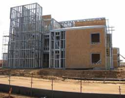
CFS framed structure. Courtesy of Don Allen of DSi Engineering.
deflection equations. This standard was referenced in the 2006 IBC. In 2007, AISI published a new edition of the Lateral Design Standard, AISI S21307, which was adopted by the 2009 IBC. AISI S213-07 contained more robust provisions for diagonal strap braced walls, provisions for seismic forces contributed by masonry and concrete, as well as Canadian provisions for CFS framed shear walls. The most recent Lateral Design Standard, AISI S213-07-S1-09, is adopted by the 2012 IBC. This document adds another steel sheet shear wall assembly and limits the aspect ratio of a diagonal strap braced wall (Figure 2) to 2:1 unless an analysis is performed taking into account joint flexibility and end moments in the vertical boundary members (end studs).
Boundary Member and Hold-down Design
One of the most discussed code provisions for CFS framed shear walls and walls with diagonal strap bracing designed using a seismic response modification coefficient, R, greater than 3 is the requirement to design the vertical boundary members (end studs) and the overturning restraint for the minimum of the amplified seismic force or the load the system can deliver. This requirement to design for increased seismic forces is found in AISI S213 Section C5.1.2.2 (shear walls) and C5.2.2.2 (walls with diagonal strap bracing) and is intended to help protect elements in the wall from premature failure and allow energy to dissipate in the sheathing to framing connections or diagonal strap bracing. The amplified seismic force is defined as the load determined using the code seismic load combinations that include the overstrength factor, Ωo. It should be noted that ASCE 7 Table 12.2-1 footnote g permits 0.5 to be subtracted from the overstrength factor when the diaphragm is considered flexible. ASCE 7-10 permits untopped steel deck or wood structural panel diaphragms to be idealized as flexible for one- and two-family dwellings, when the simplified design procedure
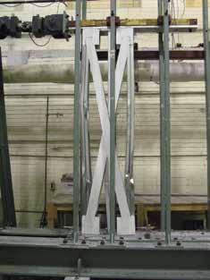
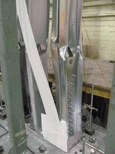
Figure 2: Diagonal strap braced wall with 4:1 aspect ratio. Courtesy of AISI & McGill University.
is used, and for light-frame structures where there is no topping on the diaphragm or where the non-structural topping is less than or equal to 1½-inch thick and each line of seismic force-resisting elements complies with the seismic story drift limitation. The nominal shear strength for CFS framed shear wall assemblies are tabulated in AISI S213. However, as AISI S213 Commentary C5.1 states, the tabulated values are based on a test protocol and the backbone curve which underestimates the nominal strength of the shear wall by up to 30%. This greater strength should be considered in design when determining the maximum the system can deliver. The nominal strength of the vertical boundary studs and overturning restraint (hold-down) is required to be greater than
ADVERTISEMENT - For Advertiser Information, visit www.STRUCTUREmag.org the amplified seismic load or the maximum load that the system can deliver. The nominal tension strength for the overturning restraint device (hold-down) is listed in the manufacturer’s literature. If the nominal hold-down tension strength is not available, designers may divide the LRFD tension strength by the resistance factor, , provided by the manufacturer, or multiply the ASD tension load by 1.2 for use with the ASD seismic load combinations with the overstrength factor as permitted by ASCE 7-10 Section 12.4.3.3.
Aspect Ratio
CFS framed shear walls, walls with diagonal strap bracing, and horizontal diaphragms have aspect ratio restrictions to limit excessive deflection of the assembly. For walls, the aspect ratio is defined as the height divided by the width (h/w), and for diaphragms it is defined as the length divided by the width (l/w). For horizontal diaphragms, the maximum aspect ratio is 4:1 for blocked diaphragms and 3:1 for unblocked diaphragms (Figure 3, page 14). The aspect ratio is limited to a maximum of 2:1 for wood sheathed, steel sheet sheathed, and gypsum board sheathed CFS framed shear walls as well as for walls with diagonal strap bracing. The ratio for wood panel or steel sheet sheathed
GT STRUDL
Structural Analysis & Design Software
Base Plate Module

New Release Version 32
Multi-Processor Solvers
• Standalone static analysis solvers take advantage of multi-core processors and the large address space available on
Windows7 7 7 7 7 64 Bit operating systems.
Performance Examples
• Linear Static Analysis: 55,000 Joints; 330,000 DOF’s 54 Loading Conditions
Solution Time (32 bit) 286 Seconds
Solution Time w/2 Processors (64 bit) 36 Seconds
• Nonlinear Static Analysis: (13th Edition AISC “Direct Analysis Method”) 2,500 Joints; 15,000 DOF’s 88 Loading Conditions
Solution Time (32 bit) 123 Seconds
The Best Choice for Infrastructure & Nuclear
Georgia Tech - CASE Center Phone: 404-894-2260 Email: casec@ce.gatech.edu www.gtstrudl.gatech.edu
Figure 4: Shear transfer near edge of concrete test specimen.
CFS framed shear walls can be increased up to 4:1 for assemblies identified in AISI S213, as long as the shear strength is multiplied by a load reduction factor equal to 2w/h. AISI S213 also permits the aspect ratio to be increased for walls with diagonal strap bracing resisting wind or seismic forces, as long as “a rational analysis is performed which includes joint flexibility and end moments in the design of the chord studs.” For walls with high aspect ratios, the chord studs develop bending moments in addition to axial forces. These bending moments can be conservatively predicted in a standard 2D frame model of the diagonal strap braced wall. If the chord studs are designed with these bending moments included, strap braced walls at high aspect ratios may still perform adequately. Fiberboard sheathed CFS framed shear walls are limited to a maximum aspect ratio of 1:1. It is also worth noting that fiberboard sheathed shear walls may be used in Seismic Design Category (SDC) A through C, and gypsum board sheathed shear walls may be used in SDC A through D.
Shear Transfer near Edge of Concrete
The 2009 IBC requires bolts embedded in concrete be designed in accordance with ACI 318-08 Appendix D where strength design or load combinations including earthquake loads are used. Although Appendix D only provides strength design procedures for use with LRFD, it’s somewhat common for engineers to divide calculated values by 1.4 to obtain allowable anchor strengths for use with seismic design. Such a calculation results in allowable loads for the embedded bolt that are significantly lower than the allowable bearing of the bolt in the CFS track. For example, the allowable shear strength in bearing for a 5/8-inch diameter anchor bolt in a 54 mil CFS track is 1860 lbs, while the allowable shear strength parallel to the edge of concrete for the embedded bolt is 364 lbs (based on SDC C through F with L-bolt embedded 7 inches and located 1¾ inch from the edge of cracked concrete with f'c=2500 psi.) To address this issue, AISI supported a research project that showed the bolt to track connection (Figure 4) provides the necessary ductility for shear wall shear anchorage, and substantiated a code exception (2012 IBC Section 1905.1.9) allowing the near edge shear anchorage design strength to be determined based on the bearing strength of the bolt in the track in accordance with AISI S100 Section E3.3.1. The exception applies to CFS track between 33 mil and 68 mil in thickness anchored with shear anchor bolts 5/8 inch or less in diameter, that are embedded a minimum of 7 inches and are located a minimum of 1¾ inch from the edge of concrete, and a minimum of 15 diameters from the end of the foundation.
Fasteners
There are several methods to attach sheathing to CFS framing including self-drilling or self-piercing tapping screws, power-driven driven smooth and knurled pins, and adhesive. While the code does not specifically recognize power-driven driven pins to attach sheathing to CFS framing, several products are recognized in product evaluation reports – based on testing – that may be referenced to determine if the application warrants their use. The code also does not specifically recognize adhesive to attach sheathing
Figure 3: Blocked wood sheathed CFS framed diaphragm. Courtesy of Don Allen of DSi Engineering. Figure 5: Winged tip and non-winged tip #8 and #10 self-drilling tapping screws.
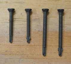
to CFS framing. Furthermore, AISI S213 Commentary Section C2 states that there is only limited testing regarding this assembly method and the data demonstrates that installations will not perform the same as an assembly with the sheathing attached to the framing with screw fasteners, and the system may have limited ductility. The typical method to attach sheathing to CFS framing is with steel tapping screws. When an R factor of 3 or more is used for the seismic force-resisting system, Table C2.1-3 must be used to determine the nominal shear strength of shear walls, and the noted limitations on screw size and framing thickness must be followed. For example, a wood sheathed CFS framed shear wall with #8 screws may not use framing thicker than 54 mil. S213 Commentary Section C2.1 states that S213 “prescribes a maximum stud thickness in order to preclude a change in failure mode of the screw fasteners.” In addition, minimum screw head diameters are prescribed in S213 Section C2.2.2 for wood sheathing attachment to the framing members (0.285 inch and 0.333 inch for a #8 and #10 screw, respectively). Screws with a winged tip and with a nonwinged tip have been used to attach wood sheathing to CFS framing. Recent full-scale testing at the Simpson Strong-Tie Tyrell Gilb Research Laboratory compared the performance of shear walls constructed with these two screw types (Figure 5). Test walls consisted of 4 x 8 foot CFS framed assemblies with 7/16-inch thick wood structural panels with #8 screws spread at 6 inches on center spacing at panel edges and 33 mil framing on one assembly and #10 screws spread at 2 inches on center and 54 mil framing on the other (Figure 6). Results showed that, while the peak loads were within 5 to 10% of one another, the assemblies with the winged tip screws were less stiff compared to the non-winged tipped
screws and this resulted in an approximate 20% design strength reduction. This may be due to the wings creating a larger hole in the wood panel sheathing, which in turn creates a less stiff assembly. Some limited testing has been conducted on wood sheathed, CFS framed shear walls to investigate the effect of overdriven fasteners, and is referenced in AISI S213 Commentary Section C2.1. The wood sheathing was 3/8inch plywood and 50% of the fasteners were overdriven by at least 1/8-inch. The results showed significantly reduced strength, stiffness and ductility for the overdriven fastener assembly, so care should be taken so as not to overdrive the sheathing fasteners.
Design Resources and Tools
There are many useful tools to help facilitate and expedite the design process. These include design guides, new product systems and connections, as well as computer software and research reports. Many of these are available from the AISI and CFSEI websites. Additional resources include the ColdFormed Steel Engineers Institute’s (CFSEI) Cold-Formed Steel Framed Wood Panel or Steel Sheet Sheathed Shear Wall Assemblies Design Guide, several CFSEI technical notes, the AISI General Provisions standard (AISI S200), the AISI Wall Stud Standard (AISI S211), the AISI Manual (AISI D100-08), and the AISI CFS Framing Design Guide
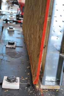
Figure 6: Non-winged self-tapping screw test assembly failure. (AISI D110-07). Currently, there is AISI supported CFS framed lateral force-resisting system research at McGill University and the University of North Texas, as well as an NEES project entitled “Enabling PerformanceBased Seismic Design of Multi-Story CFS Structures.” For more information on the NEES project, visit www.ce.jhu.edu/cfsnees.
Conclusion
construction industry. The code provisions for these systems have been revised and enhanced over the last 15 years for clarification, and new provisions have been added to increase the number of potential solutions for a given project. CFS systems have some unique design considerations, but more tools and design aids are becoming available and additional research is underway. Expect to see additional changes and improvements that will enhance the requirements and
Cold-formed steel framed lateral force- methods for successful cold-formed steel resisting systems are relatively new to the framed lateral system design.TAY24253 BraceYrslfStrctrMag.qxd 9/3/09 10:09 AM Page 1 ▪
YOU BUILD IT. WE’LL PROTECT IT.
SEISMIC PROTECTION FROM TAYLOR DEVICES
Stand firm. Don’t settle for less than the seismic protection of Taylor Fluid Viscous Dampers. As a world leader in the science of shock isolation, we are the team you want between your structureand the undeniable forces ofnature. Others agree. Taylor Fluid Viscous Dampers are currently providing earthquake, wind, and motion protection on more than 240 buildings and bridges. From the historic Los Angeles City Hall to Mexico’s Torre Mayor and the new Shin-Yokohama High-speed Train Station in Japan, owners, architects, engineers, and contractors trust the proven technology of Taylor Devices’ Fluid Viscous Dampers.
Taylor Devices’ Fluid Viscous Dampers give you the seismic protection you need and the architectural freedom you want.
www.taylordevices.com
North Tonawanda, NY 14120-0748 Phone: 716.694.0800 • Fax: 716.695.6015
Historic structures
significant structures of the past
This is Part 2 of the real story of the Structural Engineers and Architects of the Golden Gate Bridge. Part 1 (STRUCTURE® July 2012) described the history of spanning the Golden Gate. Joseph Strauss proposed a hybrid steel truss suspension bridge across the Golden Gate in 1921. From 1921 to 1930, Strauss had the good fortune to have hired Charles Ellis to be the Vice President in charge of bridge engineering and construction at his firm and have the Golden Gate Bridge District include Leon Moisseiff as an expert advisor for this monumental bridge project. The history continues. Trying to sell his vision of the bridge, Strauss mentioned Ellis’ credentials as often as he could in business meetings and proposals, often prefixing Ellis’ name with “Doctor” or “Professor.” Ellis was too immersed in his duties to pay much attention. He was spending months working out the calculations and then refining the design and details of a suspension bridge dreamed up Structural Engineers and Architects of the Golden by bridge designer, Leon Moissieff. The two visionaries worked in tandem to Gate Bridge master all of the equations necessary to calculate forces at the Golden Gate, though they were The Real Story – Part 2 separated by hundreds of miles. Telegrams flew between Ellis in Chicago and Moissieff in New By Reinhard Ludke, S. E. York, aggravating Strauss, who did not understand the complexity of the engineering work. Strauss did not understand the complex calculations or appreciate the necessity to have confidence in the calculations. This was pioneering engineering and new territory for a 4,000 foot long suspension bridge. A pioneering step that went too far proved Reinhard Ludke, S. E. is a Bridge disastrous for Moisseiff five years later when his Engineer, Principal Structural Tacoma Narrows Bridge failed in a wind storm, Engineer, for Creegan + D’Angelo with the steel girder bridge deck destroyed and Engineers in San Francisco, CA. in the water. He is the Past President of the In the twenty years from 1915 to 1935, the Structural Engineers Association science and art of long span bridge design and of Northern California. engineering went through a great deal of change. Reinhard served as the Director One man, Leon Moisseiff, was a key member of and Secretary of the Structural this revolution. Moisseiff had developed a theory Engineers Association of California to distribute wind stresses on suspension bridges by and was elected Fellow in 2010. balancing the lateral displacement of the cable and bridge deck structure. Leon began by estimating the share of the wind load carried by the truss. The remainder is supported by the main suspension cable. This generates a load line and stress limit, for both the cable and the truss. By using the principles of integral calculus, he was able to use the estimated load line to determine the shear curve and then the moment curve and the displacements along the length of the bridge. Four different integrations were required to find the slope of the elastic curve for the truss, and two integrations were required

Golden Gate Bridge – 75th Anniversary. Courtesy of Reinhard Ludke.
for the cable. The relationship of the vertical dead load – weight of the bridge – to the horizontal wind load at any point in the truss determines the slope of the suspender; once this was known, the difference between displacement of the truss and that of the suspension cable were known. Moisseff compared the calculated displacement of the truss with the calculated displacement of the main cable and suspenders. The first trial did not check, so the truss wind load line was refined and the calculations repeated until the displacement converged to a solution. Each iteration of these calculations took several days, and it required several iterations of these manual calculus calculations to converge on a solution. From these calculus integrations, Moisseiff was able to determine the displacement of the stiffening trusses which yielded the forces and stresses that needed to be supported. According to this theory, developed by Moisseiff and Frederick Lienhard, as much as half the wind pressure could be supported by the main cables in a long suspension bridge and transmitted to the towers and cable anchorage. At the same time, the deflection of the truss and of the cable would tend to balance each other, thus restoring the bridge to equilibrium under gravity loads only; after the wind stops, the lateral displacements return to zero. In a properly balanced bridge, the wind loads would not damage the bridge if it is flexible enough to bend and sway without overstressing the truss structure. The Golden Gate could be lighter, longer, and narrower than thought possible, which resulted in construction that took less time and cost less. Charles Ellis fully grasped and embraced Moisseiff’s theory and the implications of the mathematics. The Golden Gate was an opportunity to implement these new suspension bridge theories. Ellis applied this mathematics in the design for the suspension bridge. America had moved to the forefront of long span bridge engineering and construction. Strauss had abandoned his promotion of his hybrid bridge concept. It was heavy, used more material, and would take at least a year longer to construct. Leon Moisseiff worked in tandem with Charles Ellis on the engineering of the Golden Gate Bridge. Moisseiff especially contributed to the
force calculations related to wind loading on the bridge. From his New York office, he traded telegrams with Ellis in Chicago, going over numerous engineering questions. Ellis was responsible for directing the thousands of calculations required for the computation of stresses, refining the structure design, as well as development of the technical specifications, construction contracts, and proposal forms. Ellis worked tirelessly on the calculations for the suspension span, and he also tackled the frame calculations for the towers. Strauss was getting impatient with “all the time” Ellis was taking to finalize the bridge design. Ellis would not release the design until he was confident that the structural analysis calculations were correct. All these calculations had to be done manually and he did not have multiple staff members who could complete some of this complex work, so he did much of the analysis himself. Finally, on December 5, 1931, by telegram from San Francisco, Strauss insisted that Ellis take a vacation. Three days before his vacation was over, Charles Ellis received a letter from Strauss instructing him to turn all his work over to his assistant Charles Clarahan, Jr., and to take an indefinite unpaid vacation. The reason(s) Joseph Strauss removed Ellis from his pivotal role as Structural Engineer are not documented in the records. Clifford Paine took over Ellis’ role as the “Assistant to Joseph Strauss” on the project. Strauss remained as the “Chief Engineer.” For reasons not clear today, Mr. Strauss had fired Ellis. Whether it was a disagreement on technical matters, a conflict of personalities, or some other issue, Charles A. Ellis had lost his place in the engineering and design history of the Bridge and received no credit for his critical role in the final design of the landmark Bridge upon its opening. He went on to join the engineering faculty at Purdue University in 1934, from where he retired as Professor Emeritus of the Division of Structural Engineering in 1947. Forced into semi-retirement, Ellis revisited the computations for the Golden Gate Bridge. He labored over the numbers obsessively. Investing about 70 hours per week, he executed a complete review of the numbers in five months, working unpaid. Unfortunately for him, his connection with his primary obsession for so many years had been severed. When the Golden Gate Bridge opened in 1937, many men were credited with “building” it, among them Strauss, Moisseiff, and Clifford Paine, Ellis’ successor on the project. Yet Charles Ellis was not mentioned. Not until 1949, when an obituary named him as the bridge’s designer, did Ellis receive any recognition for his enormous role in the design and engineering of the bridge. Whether he ever saw or stood on the bridge is not known. In all the years Ellis spent laboring over the numbers – in ten volumes of calculated dimensions, loads, wind stresses, and the like – he had made the bridge his own. Ellis, Moissieff, and Othmar Ammann were great engineers in their own right and, for the bridge project, they brought their own unique contributions to the ultimate collective effort. Chief Engineer Joseph Strauss was the leading visionary, campaigner, and organizer for the development of the Bridge. Consulting Engineers Leon Moisseiff and Othmar Ammann were among the leading suspension bridge designers of their time; Moisseiff having developed the deflection theory and Ammann was known for developing traffic load theories which lead to design of light weight and economical bridges. Charles Ellis was the dedicated engineer performing endless calculations seeking to bring perfection to the design. He is the Structural Engineer of the Golden Gate Bridge. Clifford Paine completed the detail construction plans that carried the Ellis design to completion through construction. Resident Engineer, Russell Cone, lead the on-site construction engineers and had significant contributions in engineering the construction of complex tower foundations, erection of the towers, and managing Roebling spinning the main cables. Strauss first sought out John Eberson, a famous movie theater architect of the time, to consult on bridge design and architecture. Some of his sketches remain in the historic archives, and he is recognized for his contribution of the Art Deco vocabulary of the bridge towers. Strauss considered Eberson’s fees too high, so in 1930 he replaced the consulting bridge architect with Irving F. Morrow. Irving F. Morrow, a local Berkeley architect, is responsible for the Golden Gate Bridge’s graceful art deco design and paint color. Morrow expressed his visions in charcoal drawings. He designed small detail elements like street lamps, railings and pedestrian walkways, added vertical fluting to the bridge towers, stylized geometry in the era’s Art Deco style. He created the two magnificent 700-foot tall Art Deco Sculptures – the main suspension cable support towers. Morrow’s most famous contribution to the Golden Gate Bridge was its distinctive burnt red-orange hue called International Orange. Others had suggested the bridge be painted aluminum, dull gray, or the Navy’s preference, highly visible yellow with black stripes. He states in his April 6, 1935 report, “the bridge should be a color which contrasts with the surrounding sea, sky and land regardless of
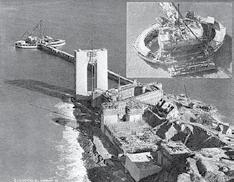
South Anchroage & Tower. Courtesy of Associated Oil Company.
weather or season.” One by one, members of the bridge’s brain trust relented, as Morrow identified a paint durable enough to need less frequent reapplication. In the end, the bridge’s design fit harmoniously into the bay’s natural palette of sky, water, and land. In early 1936, Morrow sent lighting guidelines for the bridge to Strauss. Though lighting was normally a job entrusted to electrical engineers, Strauss followed Morrow’s recommendations. After his work on the Golden Gate Bridge, Morrow returned to designing residential and small commercial buildings. The suspension bridge used less steel and was faster to build. Persuaded by these cost and time considerations, Strauss endorsed the suspension plan. Seventy five years later, the bridge that resulted from Charles A. Ellis and Leon Moisseiff’s engineering and Irving Morrow’s architecture and color is the international icon for San Francisco. It is the collective efforts of the structure engineers that created the design of the iconic Golden Gate Bridge. Joseph Strauss, Leon Moisseiff, Clifford Paine, Russell Cone, and especially Charles Ellis share the legacy that is celebrated in 2012. The contribution of each, as individuals and as a team, led to the premier suspension bridge of all time. We would not be celebrating the 75th Anniversary of the bridge without the efforts, promotion and leadership of Joseph Strauss. The imagination, engineering, pioneering technical achievements, art, and spirit of this bridge, at this location, was created by Charles A. Ellis, Leon S. Moissieff, and Irving F. Morrow. On May 25, 2012, as part of the 75th Anniversary of the Bridge, the Golden Gate Bridge District acknowledged and celebrated the contributions of Charles A. Ellis. ASCE and the Structural Engineers Association of California placed a plaque at the south bridge plaza, that states “American Society of Civil Engineers, recognizes the contributions of Charles A. Ellis, Bridge Engineer, on this 75th Anniversary of the Golden Gate Bridge.”▪
Just the FAQs
questions we made up about ... Masonry Question: Table 2 of TMS 602-11/ACI 530.1-11/ ASCE 6-11, Specification for Masonry Structures, seems to provide conservative values for the specified compressive strength of concrete masonry construction, f ' m. To achieve greater economy in our designs, we often choose to make and test prisms instead of using these tabulated values. Is there any attempt being made to reduce the conservatism in Table 2?
Answer
Table 2 of TMS 602 has been a part of building codes and standards for decades, providing a convenient method (Unit Strength method) of correlating assembly compressive strength (f'm) to unit compressive strength and mortar type. This approach to specifying or verifying concrete masonry assembly strength, however, is recognized as a tradeoff between the table’s convenience and inherent conservatism. This conservatism is a byproduct of the table’s original data, which was developed when testing practices Changing Masonry Standards were not as refined as today. To improve economy in design, Answer provided by Tyler the National Concrete Masonry Association Witthuhn, Project Engineer with (NCMA) began compiling prism test data several the National Concrete Masonry years ago to create a new unit strength table that Association. He manages research is more representative of contemporary prism projects, handles technical testing practices. The results indicated: inquiries, assists with technical • Compressive strengths are generally higher publications, and participates as than previously used in Table 2, TMS 602. staff liaison to NCMA task groups • The mortar compressive strength does not and subcommittees. impact the measured prism compressive Jason Thompson, Vice President of Engineering for the National Concrete Masonry Association, is responsible for overseeing the technical activities, services, and research for the Association. strength unless very high strength units are used. • Prisms constructed using Type S and Type N follow the same general trends, but Type N mortar has a statistical maximum of approximately 2,600 psi. • The most significant revelation from this research is that the weakest combination
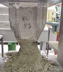
Prism specimen following compression testing.
of permitted unit strength and mortar type produces an assembly compressive strength of over 2,000 psi. A proposed new unit strength table stemming from this investigation is illustrated in the table below. It is being reviewed by the Masonry Standards Joint Committee for potential inclusion to the proposed update of TMS 602-11/ ACI 530.1-11/ASCE 6-11, Specification for Masonry Structures. Once adopted, the ease and convenience of the unit strength method will continue, albeit without the inherent conservatism in previous versions of this table. The research shows conclusively that properly constructed and tested concrete masonry always produces prism strengths greater than 2,000 psi, regardless of mortar type. Therefore, in the near future, there will be no need to specify f ' m values less than 2,000 psi. The increased net area compressive strengths (f ' m) derived from the proposed table will facilitate the design of more economical and sustainable concrete masonry structures. The full version of the research report and its conclusions will be posted summer 2012 at the following link: www.ncma.org/resources/design/ Pages/ResearchReports.aspx. ▪ Proposed New Unit Strength Correlation for Concrete Masonry
Net Area Compressive Net Area Compressive Strength of Masonry, psi (MPa) Strength of Concrete Masonry Unit, psi (MPa) Type M or S Mortar Type N Mortar 2,000 (13.8) 2,000 (13.8) 2,000 (13.8) 2,500 (17.2) 2,500 (17.2) 2,500 (17.2) 3,000 (20.7) 2,700 (18.6) 2,600 (17.9) 3,500 (24.1) 2,800 (19.3) 4,000 (27.6) 3,100 (21.4) 4,500 (31.0) 3,200 (22.1) 5,000 (34.5) 3,600 (24.8) 5,500 (37.9) 4,000 (27.6) -

Fewer screws = lower installed cost



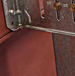
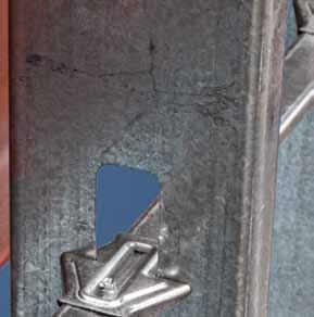
Our latest innovation for cold-formed steel construction is the new Simpson Strong-Tie® SUBH wall-stud bridging connector. It requires only one screw for most installations, reducing wall-stud bridging connector. It requires only one screw for most installations, reducing the installed cost over conventional clip-angle connections that require four screws. The the installed cost over conventional clip-angle connections that require four screws. The SUBH connector features a unique geometry that grabs the stud web and fi ts snug SUBH connector features a unique geometry that grabs the stud web and fi ts snug over 1.5" U-channel, enabling superior rotational and pull-through resistance. It over 1.5" U-channel, enabling superior rotational and pull-through resistance. It is self stabilizing and does not require an extra hand or C-clamps to hold the is self stabilizing and does not require an extra hand or C-clamps to hold the connector while a screw is being driven. The SUBH connector is the only connector while a screw is being driven. The SUBH connector is the only bridging connector/device that has been extensively tested as a system so that the tabulated design values refl ect stud web size and thickness. that the tabulated design values refl ect stud web size and thickness. The SUBH can be used with a wide range of stud sizes and gauges. The SUBH can be used with a wide range of stud sizes and gauges. Learn more by visiting www.strongtie.com/subh or calling (800) 999-5099.
InSIghtS
new trends, new techniques and current industry issues

The image shows a structural steel bracing member at three LOD levels. The LOD 300 brace is for permit level structural documents. LOD 350 brace with gusset plates is for trade coordination and LOD 400 brace with welds is for shop drawings.
No technology has applied as great of an external force of change to the structural engineering profession as Building Information Modeling (BIM). BIM is requiring firm owners to be flexible as project scopes, and possibly their standard of care, evolve. The trend for Level of Development in BIM building owners requests for the design teams to share their 3D By Will Ikerd, P.E., CWI, models with contractors continue to increase. LEED AP Additionally, building officials are beginning to look at structural models as the deliverable for automated code checking. The need for tighter scope definition highlights the importance of establishing the Level of Development (LOD) of BIM structural elements. All structural engineering firm owners in 2012 must take an active role in understanding the changes BIM enables in the building industry, and how to properly define the scope of their base services as well as additional services. Mr. Will Ikerd P.E., CWI, This article addresses the background of the LEED AP is principal at IKERD LOD concept, discusses the author’s newly proConsulting. Mr. Ikerd currently posed LOD 350, and discusses current trends in co-chairs both the Designers LOD. Most importantly, no two sets of firms, Forum of the AGC’s national projects, contract forms, or clients are the same. BIM Forum and the Structural There are many different opinions on the topic Engineering Institute’s national of who should model what and to what LOD. BIM Committee. Additionally, he Some firms seek to limit the LOD they model co-chairs the AGC BIM Forum in an effort to manage risk within traditional fee – AIA workgroup on Structural structures. Others seek to expand their scope for LOD. He may be contacted at additional fees and possible risk. The importance structures@IKERD.com. of LOD is that it allows all of these firms to clearly define the scope they choose. The AIA E202 document contains a table for defining the “Level of Development” of the BIM (AIA E202 § 1.2.3 Model Element) on a scale of 100 to 500. LOD in AIA E202 describes the level of completeness to which a model element is developed. It is important to emphasize that LOD only applies to individual model elements and not an entire model. For example, there is no such thing as an LOD 300 model when defining scope. Additionally, a model element author is defined as the party responsible for developing the content of a specific model element to the LOD required for a particular phase of a Project. Definition of the intended use of the model elements is also possible in E202, which addresses use cases. Currently, the dominant use case for structural engineers is the creation of 2D documents. Other structural use cases are estimating, 3D spatial validation (clash detection), automated (CNC) fabrication, and many others, such as automated structural code checking in building departments. Model elements at LOD 100 may be graphically represented with a symbol, but they do not have any indication of actual physical geometry. For structures, there is seldom any content modeled at LOD 100. Information related to the model elements (i.e., cost per square foot, steel or reinforcing pounds per square foot, etc.) is often derived from a textual structural narrative that the engineer provides to accompany the architects early mass model of the building. At LOD 200, an element is graphically represented as a generic system, object, or assembly with approximate quantities, size, shape, location, and orientation. From this point the model elements progress to LOD 300 where it is graphically represented as a specific system, object or assembly which is accurate in terms of quantity, size, shape, location, and orientation. For full trade coordination, however, additional element development is often needed beyond LOD 300. For this reason, the author has advocated on the joint BIM Forum (AIA working group on LOD) for a newly proposed LOD 350, “Assemblies for Coordination”. LOD 350 is defined as the Model Element being graphically represented within the Model with the detail necessary for cross-trade coordination and construction layout. Beyond 350 is LOD 400, “Detailed Assemblies.” At LOD 400 the model element is graphically represented as a specific system, object or

assembly that is accurate in terms of size, shape, location, quantity, and orientation with detailing, fabrication, assembly, and installation information. While LOD 500 is beyond the scope of this discussion, it is the model element level where As-Built and facility management information is integrated into the model elements. Nongraphic information may also be attached to the model element at any LOD. The Figure shows an example of LOD with a main structural steel brace member at three different LOD levels. At LOD 300, the brace is sufficiently developed to create permit construction documents with plan and framing elevation images. However, for cross trade coordination with MEP systems, for example, the construction team needs the member’s gusset plates modeled which correlate to a brace at LOD 350. After trade coordination, the brace element would be developed further to LOD 400 for fabrication level modeling. This level includes all the connection information of the brace needed for shop drawing creation and computer numeric controlled (CNC) automated fabrication and welding. In structural design models, main structural members and systems are normally modeled with standard modeling tools for the creation of 2D construction documents. Higher levels of structural element information are usually proscribed with typical details. Examples of these structural elements are gridlines, levels, columns, beams, slabs, walls, main gravity systems and main lateral systems. Construction drawings made from the LOD 300 model are accompanied by additional 2D information such as general notes, typical details, specific details and specifications to define higher level information not typically shown in 1/8-inch scale plans or modeled for permit drawings. Most main structural member elements are at LOD 300. However, structural engineers must be mindful that LOD 300 requires elements to be in the correct location. Thus, sloping roof members that are modeled flat are not at LOD 300, even though the 2D plans made from them appear correct. Other areas of misunderstanding are structural elements shared with architecture such as tilt walls, slabs and load bearing masonry walls. The structural engineer’s scope should address who is responsible for modeling items such as floor depressions, openings, top of wall heights of parapets, etc. Future trends to look for are new use cases for models that include automated structural code checking. Such trends may require structural engineers to expand their traditional scope to include modeling elements to a higher LOD during design, including gravity and lateral loading along with classifications for special inspection requirements for each member. Regardless of one’s personal opinions of how the structural profession should use BIM, few fail to see that BIM use is expanding in structures far beyond just a tool for creating 2D documents. The significance of the LOD concept is that it is an important tool to help define the structural engineer’s scope in BIM. For additional information on this topic, visit www.SEIBIM.org for resources on the topic or send an email to structures@IKERD.com. ▪
Structural DeSign
design issues for structural engineers Modern container terminals are often built on sites with existing infrastructure like tunnels, sewers and pipelines. Sometimes the relocation of these obstructions is not feasible. These conditions often require the engineering of long-span trusses for container cranes. Nowadays, availability of suitable waterfront industrial sites dictates the direction of development of new port facilities. This article gives some insight into the most critical issues of the design of waterfront crane trusses and discusses fatigue, dynamic impact allowance, torsional resistance, effect of dynamic impact on fatigue, fracture critical connections and buckling analysis of built up box elements. Other important issues discussed include the impact of the environment on corrosion fatigue, methods of corrosion protection within ice fluctuation zones, and proposed deflection and camber criteria for long-span crane ways.
Background
Survival of a Crane Truss in a Waterfront Project Cyclical movements of long-span crane girders and crane trusses have been identified as the cause of many structural Part 1 failures in the past. Repeated fluctuating loads can result in fractures at stress magnitudes well below By Vitaly Feygin, P.E. elastic failure in monotonically loaded elements and connections. Failure due to accumulation of plastic deformation is known as fatigue. Normal fatigue can be described as a process of cumulative plastic damage in a non-aggressive environment. Fatigue aggravated by a corrosive environment is known as corrosion fatigue. Fatigue normally develops at connections or discontinuities where local stresses exceed the steel yield stress. Vitaly Feygin, P.E. is a principal Accumulated plastic damage initiates a crack, structural engineer with Marine which in turn aggravates the discontinuity and and Industrial Consultants, with increases stress in the remaining part of the conoffices in Baltimore and Tampa. nection, causing crack propagation and ultimately He is the author of two patents structural failure. Geometry of the detail, materelated to sea walls, composite rial and weldment quality is described by stress cofferdams, bridge fenders and port category. The AISC 13th Edition and AASHTO structures. He may be reached at LRFD 4th Edition define eight such categories, vfeygin.mic@gmail.com. each described by a reliability constant (Cf) and an endurance limit, called the stress threshold (FTH). The temperature and aggressiveness of the medium also affect fatigue resistance. Among the most effective methods of increasing the fatigue lifespan of a connection are: • Upgrading the stress category. • Reducing the stress range. • Decreasing the severity of stress concentrations.
The online version of this • Implementing corrosion protection. article contains detailed Stress concentrations can be reduced by incorreferences. Please visit porating smooth transitions with large radii and www.STRUCTUREmag.org. avoiding sharp geometrical discontinuities in welds.
Figure 1: Constant amplitude cycle loading.
Figure 2: Variable amplitude cycle loading.
Corrosion fatigue behavior is affected by the same parameters as normal fatigue. However, in a corrosive environment, the fatigue threshold limit is lower and crack propagation is faster at all stress intensity levels. Common corrosion types – particularly crevice, pitting and inter-granular corrosion – affect crack propagation. Pitting corrosion is the most damaging type. How much should the threshold limit be lowered in a corrosive environment? There is no definitive answer, but it would be reasonable to reduce it by 10-15% unless a protective coating can provide reliable protection. Frequently the weld becomes the source of stress concentration, which itself leads to accelerated corrosion, which in turn increases the chances of fatigue. The whole process can be described by a simple sequence of events:
Corrosion → Stress Concentration →
Accelerated Fatigue, or Stress Concentration → Corrosion → Growing Stress
Concentration → Accelerated Fatigue On many occasions, corrosion is initiated in transition welds, at weld discontinuities and at sharp transition angles.
Stresses Affecting Long-Span Crane Trusses
Crane trusses undergo a complex, fluctuating loading cycle. An overview of fluctuating load terminology can be seen in Figure 1 and Figure 2.
Stress cycles shown in Figure 1 represent ideal constant-amplitude fatigue stresses. However, actual stress fluctuation is much more complex; a graph would show several short-term load cycles. Each cycle can be described by three operations: • Load pick-up (maximum load on crane wheels). • Load carry-over into the loading bay. • Unloading (minimum load on crane wheels). A new short-term load cycle starts when a crane moves into a new stationary position. There are also sub-cycles, characterized by crane travel between stationary positions. Sub-cycles are the least frequent events. The type of load fluctuation described by the curve shown in Figure 2 is known as variable-amplitude loading. The cycle with the largest stress range is called a primary cycle. Crane relocation and operation from other stationary positions along the truss creates a series of secondary cycles, with much smaller stress range magnitudes. Therefore, the estimated fatigue life of the connection should be based on an equivalent constant-amplitude fatigue stress range, rather than the maximum stress range.
Engineering for Fatigue
Stresses during the cyclic load are described by several parameters (Figure 1), including the maximum stress (fmax), the minimum stress (fmin), and the stress range (fsr = fmax – fmin). Another important parameter, called the stress ratio (R = fmin/fmax), is strangely missing from the AASHTO LRFD 4th Edition and AISC 13th Edition. Figure 1a shows idealized cyclic stresses with complete stress reversal, R =–fmin / +fmax = -1. Figure 1b shows compression to tensile stress reversal with compression stress –fmin = – (0.5 +fmax), R = – 0.5. Figure 1c shows cyclic stresses with zero to full tensile stress, R = 0 / +fmax = 0. Figure 1d shows a tensile to tensile stress cycle, 0 < R < 1. Both fmax and fmin have positive signs. Figure 3 shows the fatigue limit correlation for different stress ratios, R = -1, R = 0 and R = 1. The fatigue strength was compared at 2,000,000 cycles and significantly decreases as the stress ratio decreases from R = 0 to R = -1. The fatigue limit with stress ratio 0 < R < -1 can be analytically interpolated from S-N stress curves shown in the USS Steel Design Manual for A36 and A50 steels. The threshold stresses shown in Table A-3.1 of AISC 13th Edition and Table 6.6.1.2.5-3 of AASHTO LRFD 4th Edition were referenced to a complete stress reversal cycle (R = -1). Comparison of the data streams indicates that threshold limits, referenced by both manuals, lead to overly conservative results. Table 1 will help the designer to justify a constant-amplitude fatigue threshold (FTH) based on the stress ratio (R). Load Combinations and Dynamic Impact The dynamic vertical load is a random event. The main cause of impact is a combination of crane rail vertical misalignment and crane loading – e.g., unloading operations. Crane rail vertical misalignment affects impact during crane sub-cycles, and therefore should not be combined with impact Figure 3: Comparison of fatigue strength of as received due to loading-unloading operations. structural steel plates at 2,000,000 stress cycles. AISE Technical Report No 13 sets crane rail vertical misalignment criteria at ¼-inch. In δmax = δst (1+ T/πτ *sin(πτ/T)) (Equation 1) the absence of any better references, designers where, of waterfront crane railways should indicate (1+ T/πτ *sin(πτ/T)) = the dynamic amplia ¼-inch vertical misalignment as a practical fication factor; design limit. Presently, documents used for the τ = is the duration of the impulse; and, design of crane ways, notably AISC 13th Edition T = is the period of the first mode, known as and UFC 4-152-01, Design: Piers and Wharves, the fundamental natural period. prescribe a 25% impact factor applied to the Reverse analysis of Equation 1 presented in maximum listed wheel loads of the crane bogie. Table 3 (page 24) shows the (τ/T) influence A paper presented by P. H. Griggs (1976) indi- on impact results. Table 3 explains why meacated that measured vertical impact typically sured impacts were never larger than 7% of that does not exceed 7% of the vertical static load predicted by Equation 1. Weaver provides the on a crane wheel. The summary of suggested following explanation for measured impact phevertical impacts referenced by different sources nomena: “Actual tests have shown that impact is illustrated in Table 2 (page 24). on the crane girders rarely exceeds 5 to 7% of The impact produced by a crane lift is static load, even for relatively fast hoist speeds, explained by the ramped impulse equation due to cushioning effect resulting from torsiondescribed by S. P. Timoshenko (1974): spring action of the ropes (cables) and leaf-spring
Table 1: Fatigue threshold limits.
Stress Category Reliability Factor, Cf Stress Ratio, R Threshold Limit, FTH (ksi) A 250*108 0 33 ( 0 to tensile) 250*108 -1/2 33 (partial reversal) 250*108 -1 24 (full reversal) B 120*108 0 26 (0 to tensile)
120*108
120*108 -1/2 21 (partial reversal)
-1
16 (full reversal)
B’ 61*108 0 20 (0 to tensile)
61*108
61*108 -1/2 16 (partial reversal)
-1
12 (full reversal)
C 44*108 0 16 (0 to tensile)
44*108
44*108 -1/2 13 (partial reversal)
-1
10 (full reversal)
D 22*108 0 11 (0 to tensile)
22*108
22*108 -1/2 9 (partial reversal)
-1
7 (full reversal)
E 11*108 0 7 (0 to tensile)
11*108 -1/2 6 (partial reversal)
Reference
Griggs Whiting Crane Handbook.
Russian Standard, SNIP 2.01.7-85 for Container Cranes (GOST 25546-82)
action of the girders.” The boom of the container crane compliments leaf-spring action of the crane girder. A more gradual rise of the impulse duration reduces the effect of dynamic amplification. Since 1991, many crane girders used for support of heavy 300- to 400-ton steel mill cranes were successfully designed using a 10% impact factor applied to the maximum listed wheel load. Russian SNIP 2.01.7-85 has prescribed a 10% impact allowance applied to crane wheel loads since 1975. The majority of sources that have done independent research on impact agree that a 25% impact factor is overly conservative and highly unrealistic. Tables 4 and 5 present load combinations suggested for crane way analysis. Notice that impact in these load combinations is taken as 10% of the static wheel load. Very similar load combinations were suggested by Bhimani and Soderberg (2006). The impact suggested by Bhimani and Soderberg was included in load combinations WOP1 and WOP2 with 50% of the AISC 13th Edition and UFC 4-152-01 recommended value, virtually restricting the effect of vertical impact to 12.5% of the static load acting on the crane wheel. The author strongly believes that a 10% vertical dynamic impact allowance for crane runway design is a reasonable and sufficiently conservative assumption. Crane History UFC 4-152-01 and the AISC 13th Edition have no provisions for fatigue design based on variable-amplitude loading. Design based on a maximum stress range coupled with the maximum number of load cycles is beyond reasonable conservatism. A properly designed long-span crane truss is always based on the anticipated future loads. “Future history” can be created by the facility operator, using data from the assumed ship sizes and scheduled arrivals. The ship data helps to locate the crane stationary positions for loading-unloading operations. Crane positions predetermine primary and secondary short-term load cycles for each critical location along the truss span. For fatigue analysis, all short-term load cycles are compiled into one variable-amplitude loading case. Fatigue analysis of all tension elements and connections of the structure is based on
Description
≤ 7% of the crane static load
5% to 7% from sum of hoist lifted load and weight of grappling device. 10% of the crane static load on the crane bogie wheel.
statistical formulas known as Miner’s Rules and fatigue resistance curves. Miner’s Rules Fatigue analysis based on maximum stress levels and the maximum number of cycles yields ultra-conservative results. Shilling et al. (1979) expanded the Miner’s Rule for the case of variable-amplitude loading. The first rule of that analysis states that the stress response of each joint is based on a fatigue damage ratio, which should not exceed unity: D = Σ (n / N) (Equation 2) where, n = number of cycles applied at a given stress range.
Table 4: Suggested service load combinations. Table 3: Theoretical impact. δmax== δst * τ/T *[(1+T/πτ*sin(πτ/T)] 1.000 1.00δst 0.500 1.63δst 0.250 1.90δst 0.125 1.97δst 0.000 2.00δst
N = number of cycles for which the given stress range would be allowed by the appropriate S-N curve. The second rule implies that the effective stress range is equal to the cube root of the mean cube of the stress range. Seff = (Σ(ni/Ntotal) * S3 ri)0.333 (Equation 3)
S-N Curves Fatigue resistance is derived from exponential curves, called the S-N relationship, where N is the number of cycles to failure and Sr is the stress range. N = Cf / Sn r (Equation 4) n = 3 for all stress categories except F.
Operating Mode WOP1 * WOP2** WOP3*** Stowed Crane Dead Load, DL 1.0 1.0 0.66 1.0 /(0.66) Lift System, LS 1.0 1.0 0.66 1.0 /(0.66) Lifted Load, LL 1.0 1.0 Impact Load, IL 0.1(LS+LL) 0.1(DL+LS+LL) Operational Wind, OWL 1.0 / (0) 1.0 / (0) Storm Wind Load, SWL 1.0 Earthquake Load, EQ Collision Load, CL 0.66(DL+LS)
Table 5: Suggested factored load combinations.
Operating Mode WOP1 * WOP2** WOP3*** Stowed Crane Dead Load, DL 1.2 1.2 1.0 1.2 /(1.0) Lift System, LS 1.2 1.2 1.0 1.2 /(1.0) Lifted Load, LL 1.6 1.6 Impact Load, IL 0.1*1.6(LS+LL) 0.1*1.6(DL+LS+LL) Operational Wind, OWL 1.6 / (0) 1.6 / (0) Storm Wind Load, SWL 1.6 Earthquake Load, EQ Collision Load, CL 1.0(DL+LS)
NOTES: * Load Combination for load pick up ** Load Combination for load carried by crane along the crane way within the crane loading bay. *** Factors shown in parenthesis / ( ) are given for load cases when wind load causes uplift.
Figure 4: Crane truss elevation.
Cf = stress category reliability coefficient. Sr = design service load stress range. The S-N curves were developed for different stress categories and are presented in the AISC 13th Edition and AASHTO LRFD Specifications Tables (based on constant-amplitude, full-stress-reversal loading). The following example provides step-by-step direction on how to determine the service life of a connection detail, converting variable-amplitude stress ranges into an equivalent effective stress range. Example 1 Assume four short-term load cycles. Figure 4 shows a crane truss with four stationary positions. Obviously, the designer can select stations at 1 foot o.c. However, experienced designers should select strategic stations, allowing for a more efficient analysis. Load cycle #1 denotes the primary load cycle. Load cycles from #2 to #4 are secondary load cycles for investigated stationary positions of the crane. Thus, each crane stationary position denotes the cycle number. Service load stresses imposed by each load cycle at the connection are shown in column Sri. The number of stress ranges for each cycle is shown in column ni. Table 6 gives the number of cycles per day; the ideal time history will be based on a longer term. The longer the time history, the greater the analysis precision. Analyses of the effective stress range and fatigue damage ratio are presented in Tables 6 and 7. The result of the analysis compiled in Table 6 shows that the effective constant-amplitude stress range Seff, = 14.12 ksi. Using the S-N relationship formula (Equation 4), the designer can calculate the equivalent number of cycles, or fatigue life, of the connection. N = Cf /Sn r for stress category B, (n = 3) NB = 1.20*1010 / 14.123 = 4,262,625 cycles If the stress category is changed to B', the number of load cycles will become significantly lower:
Figure 5: Fatigue resistant box section for truss fabrication.
NB'= 0.61*1010 / 14.123 = 2,166,835 cycles. Knowing the estimated number of annual cycles, the designer can estimate the lifespan of the structure. Assuming 160 cycles per day or 160 x 365 = 58,400 per year, the life span of the connection, NB'years = 2,166,835 / 58,400 = 37.10 years for Stress Category B'. NB years = 4,159,059 / 58,400 = 71.21 years for Stress Category B. Fatigue life of the structure is determined from the lowest number of cycles attributed to each joint. Similar checks should be made for each connection detail subjected to tensile stresses. In general, the design fatigue life of each joint and member should be at least 25% longer than the intended service life of the structure. In other words, all elements have to be designed with a safety factor of 1.25. The lifespan of the structure can be derived from the limit imposed on the fatigue damage ratio, D < 1.0 (Equation 2). An analysis of the Fatigue Damage Ratio is compiled in Table 7. NB' years = 1.0 /0.02 = 50 years for Stress Category B'. The estimated service life of the truss derived from Equations 3 and 4. N service = 37.10 / 1.25 = 30 years All connections and joints of the crane truss should be specified with prequalified full-penetration welds. Weldments prone to lamellar tear must be excluded. Weldment details recommended for the best fatigue resistance performance are shown in Figure 5. Connections designed with the highest stress category and lowest stress range, Sr, will have the best fatigue resistance.▪
Part 2 of this article will appear in an upcoming issue of STRUCTURE.
Table 6: Analysis of effective stress range, connection 1, miner rules, equation 4.
Table 7: Analysis of fatigue damage ratio, connection 1, miner rules, equation 3.
Ntotal =160
Stress Category B’
Sri, ni number of S eff, Cycle # Cf ksi stress ranges Sri ni / Ntotal (ni / Ntotal)*S3 ri ksi 1 0.61*1010 18 40 0.25 1458.0 2 16 40 0.25 1024.2 3 10 40 0.25 250.0 4 7 40 0.25 85.75 14.12 Σ(ni / Ntotal)*S3 ri) = S3 eff = 2,817.9
Stress Category
Cycle #
Sr Stress Range B’ (n=3) n Cf N=Cf / Sn
r n / N
1 18 40*365 0.61*1010 1,045,953 0.0104 2 16 40*365 1,489,258 0.007 3 10 40*365 6,100,000 0.0018 4 7 40*365 17,784,256 0.0006
Practical SolutionS
solutions for the practicing structural engineer
Ө Ө
Ө
Designing Column Base Plates for Uplift
Figure 1: 45-degree-progression bending plane.
According to the father of the atomic age, Albert Einstein, we should all try to “Make everything as simple as possible, but not simpler.” In the spirit of this admonition, the following article describes a simple way to analyze steel in bending, and specifically a steel base plate supporting an HSS column subject to uplift forces. Once properly understood, the method can be used for most conceivable configurations of steel components where a flat-plate-bending, bending plane can be identified. For comparison purposes, a corresponding base plate analysis will also be performed using the AISC procedure for locating the bending plane of a base plate supporting an HSS column. We will analyze a 14-inch x 14-inch base plate, supporting an HSS 8x8 column resisting a net ultimate uplift of 40 kips. The steel design reference will be the 13th Edition of the AISC Steel Construction Manual (AISC 13th Edition). The anchor bolts, that secure the base plate to the foundation, are symmetrically placed at the column corners. Following clear spacing guidance in Table J3.4 of the AISC 13th Edition, each anchor bolt is located as shown in Figure 1. Since the anchor bolts are symmetrically placed, and the base plate is a uniform thickness, they share the 40 kips equally. Therefore, each bolt resists 40 kips / 4 or 10 kips of uplift. The more difficult challenge is to locate the bending plane, and corresponding effective width, in the base plate as the column is pulled upward. If we assume that the bending plane is located at the column corners and the area of steel developed is based on a 45 degree distribution of the tension force from each bolt, the base plate’s bending plane can be visualized as shown in Figure 1. Using this approach, the required base plate thickness based on the flexural strength of the bending plane is just under 0.75 inches. 45-Degree-Progression Bending Planes vs AISC HSS Base Plate Bending Planes
By Dan Mazzei, P.E.
Dan Mazzei, P.E. is an Associate at Wallace Engineering, headquartered in Tulsa, OK. He is a member of the American Concrete Institute and a member of the Oklahoma Structural Engineers Association. Dan can be reached at dmazzei@wallacesc.com.
Ө
Figure 2: AISC HSS base plate bending plane.
For comparison purposes, our next step would be to locate the bending plane per the AISC 13th Edition, Chapter 14. It is important to note that this procedure is based on a base plate designed for gravity loads, but it can still be used to locate the bending plane for net uplift. Using the same base plate configuration, we will identify the plate width (B) = 14 inches and the base plate length (N) = 14 inches. With the base plate’s bending plane being near the face of the column and considering the portion of the base plate beyond the face of the column as cantilevered out to the edge of the base plate, the actual location of the bending plane is the greatest of m, n and λn' from the edge of the base plate. As shown in Figure 2 and per AISC 13th Edition, Chapter 14, for a square HSS shape m = n = [N – (0.95)(column width)] / 2 = [14–(0.95)(8 inches)]/2 = 3.2 inches This dimension is the distance from the edge of the base plate to the bending plane in the base plate near the face of the column. For a base plate subjected to gravity loads, the 3.2 inch dimension must then be compared to the theoretical location of the bending plane based on yield line theory, λn'. However, the calculation for λn' is not applicable for a net uplift condition since it is dependent on the capacity of the base plate with respect to concrete crushing (i.e. Pu / Pp). See Punching Shear In Thin Foundations in the April 2012 issue of STRUCTURE Magazine. Therefore, the bending plane for uplift loads is at m = n = 3.2 inches. In other words, this calculation shows that the bending plane is 3.2 inches from the edge of the base plate. Up to this point, the AISC procedure for determining the dimensions m and n is essentially the same as what is used when designing a base plate in bearing with continuous support by a footing (i.e. what is shown in AISC 13th Edition, Chapter 14). However, since the base plate is supported in the reverse direction by the heads of the anchor bolts, the bearing plate procedure cannot be used to solve for the moment in the effective section nor for the required base plate thickness. Instead, the location of the bending plane from the center line of the anchor bolts can be found by subtracting the bolt’s clear space (1½ inches for the edge of the plate) from the 3.2 inch dimension determined above, giving 3.2 inches – 1.5 inches = 1.7 inches. This is the dimension between the bolt’s centerline and the bending plane, and is also the moment arm needed to solve for the moment at the bending plane. The moment at the bending plane is simply the tension load on two bolts multiplied by the 1.7 inch moment arm. Since both sides
Ө
Figure 3: Bending at horizontal leg of ledger angle example.
resist the load equally, the moment at the bending plane is, M = Tu/2 x 1.7 inches = 40 kip/2 x 1.7 inches = 34 kip-inches. Using the same logic as shown in Figure 1, the effective section for this case is the full length of the base plate and the required thickness can be determined as follows: t = [(4)(M) / (0.9)(b)(Fy)]1/2 t = [(4)(34 kip-inches) / (0.9)(14 inches)(36)]1/2 t = 0.55 inches As you can see, the required thickness, based on the AISC HSS base plate bending plane, is less than that based on the 45-degreeprogression bending plane. This is because the latter accounts for unbraced base plate corners by using a reduced effective section. Therefore, the 45-degree-progression procedure is both simpler, more accurate, and will result in a more conservative design (i.e. a thicker base plate) when designing for uplift. Another example of how useful the 45-degree-progression bending plane procedure can be is shown in Figure 3. This calculation checks a ledger angle’s ability to support a load applied near the toe of its horizontal leg. The procedure is the same as that outlined in Figure 1 and simply shows that the required thickness of a steel component is easily determined by identifying the bending plane, calculating its section modulus, calculating the applied bending moment at the bending plane and then determining how much steel is necessary to resist the bending moment. In conclusion, I hope that the reader can see how useful and simple the 45-degree-bending plane procedure can be when checking the capacity of steel components. It has helped me, on several occasions, check the capacities of structural components for which there was no clearly defined design procedure.▪
Development of Composite Steel Deck
By Thomas Sputo, Ph.D., P.E., S.E.
Steel decking was first used to support a concrete floor in the 1920s. Loucks and Giller described a steel-deck system in a patent filed in 1926. In this early development, the steel deck provided all the structural resistance, concrete was added to provide a level walking surface and fire resistance. The use of steel deck was attractive to constructors as it served as permanent formwork and construction platform, and was an attractive alternative to reinforced concrete slab floors. By 1938, engineers were using a non-composite cellular floor system produced by the H.H. Robertson Company (referred to as the keystone beam because of the dovetail shape of the steel deck cross section) in industrial buildings.
History of the Steel Deck Institute
Organized in 1939 as the Steel Roof Deck Industry Technical Committee, the name of the organization was changed in 1947 to the Metal Roof Deck Technical Institute and changed again in 1964 to the Steel Deck Institute. The steel roof deck industry’s first design specification was dated June 1945 and Suggested Architect’s Roof Deck Specifications and Code of Recommended Standard Practice were adopted in 1948. Standard load tables for roof decking were first adopted in 1966. Specifications and commentary for composite steel floor deck were adopted and published in 1978. The SDI today consists of 16 Member Companies that manufacture steel deck, and 14 Associate Member Companies that manufacture related products used in the production or erection of steel deck. The Institute is involved in a broad range of activities associated with the engineering, design, production and field usage of steel decks developed through the combined efforts of the entire membership. SDI Member Companies are responsible for the production of approximately 95 percent of the steel deck used in the United States. Free downloads of all SDI Standards, white papers, additional technical resources, and additional information regarding the SDI and its member companies can be found on the SDI website, www.sdi.org. The first composite slabs, concrete reinforced by the steel deck, appeared in the 1950s. The first was a product known as Cofar, produced by the Granco Steel Products Company, which was a trapezoidal deck section with cold drawn wires (T-wires) welded transversely across the deck ribs. The slab was analyzed as a traditional reinforced concrete slab and found to be in good correspondence between predicted and experimental strengths. In 1961, the Inland-Ryerson Company produced a trapezoidal steel deck with indentations rolled into the profile to achieve horizontal shear transfer between the concrete and steel. This floor deck, known as HiBond, was the forerunner of most modern composite steel decks that use embossments to develop bond between the concrete and the deck. By the mid 1960s, a number of manufacturers were producing composite steel decks, validating the load carrying capacity of the composite slab through proprietary testing. Each steel deck manufacturer, employing sound engineering design principles, developed their product by extensive independent research so that the approving building code agency would grant acceptance of the particular steel deck system. In many cases the local building code official requested additional test data from the manufacturer, depending on the particular construction situation. This, resulting from the independent nature of the competitive product, created costly situations that caused an adverse affect on steel deck reinforced floor construction.
Loucks 1926 Patented Deck.
Recognizing the need for one design standard, the American Iron and Steel Institute (AISI) initiated a research project in 1967, at Iowa State University under the direction of the late Professor Carl Ekberg, to develop a basis for the design criteria related to composite steel deckslabs. Extensive research by both Professors Carl Ekberg and Max Porter at Iowa State, and other researchers at University of Waterloo, Lehigh University, Virginia Polytechnic Institute and State University, West Virginia University, and the University of Washington, resulted in a body of public domain knowledge on composite steel deck-slabs.
H.H. Robertson Patented Composite Deck.
These research efforts resulted in the American Society of Civil Engineers (ASCE) developing the ASCE 3-84 Specifications for the Design and Construction of Composite Slabs by the Steel Deck with Concrete Standard Committee under the leadership of Professor Porter. This document was again revised in 1991. Both the 1984 and 1991 documents were recognized by the model building codes as an acceptable standard for the design of composite deck-slabs. Having a building code recognized design standard simplified the acceptance process for composite steel deck by building officials, and resulted in the growth of the market for this product. The first Steel Deck Institute (SDI) Composite Deck Design Handbook was published in 1991, with a revised edition in 1997. Recognizing changes in technology, the SDI began activities to develop new standards for composite deck slabs, initially publishing the ANSI/ SDI C1.0 Standard for Composite Steel Floor Deck in 2006. The 2006 Standard was revised and expanded in 2011 with the ANSI/SDI C-2011 Standard for Composite Steel Floor Deck-Slabs and the ANSI/SDI T-CD-2011 Test Standard for Composite Steel Deck-Slabs. Over the past 80 years, the design of composite steel floor deck has evolved from empirical design based on testing into a product with well-understood behavior and mature design standards that are recognized by the building codes. This evolution has lead to a more efficient and cost effective floor system.▪
Thomas Sputo, Ph.D., P.E., S.E. is the Technical Director of the Steel Deck Institute. Additionally, he is a consulting structural engineer with the Gainesville, FL firm of Sputo and Lammert Engineering, LLC, and a Senior Lecturer in the Department of Civil and Coastal Engineering at the University of Florida.
ADVERTISEMENT - For Advertiser Information, visit www.STRUCTUREmag.org

Missouri Enacts First “Peer Review” Privilege for Design Professionals
By G. William Quatman, Esq., FAIA
To encourage open and candid discussions, U.S. law prevents some communications from being revealed in court. Common examples are those between a lawyer and client; a priest, rabbi or member of the clergy and a member of his or her synagogue or church; a physician, surgeon, therapist or psychologist and patient; and an accountant and client. These protections are called a legal “privilege” and date to the early 1800s. Some of the first privileges covered communications between doctors and their patients. In later years, courts questioned whether one doctor’s “peer review” of another doctor’s work would be protected by the same privilege. A Missouri lawsuit in 1984 answered this question in the negative, finding that there was no privilege for statements or documents by medical personnel participating in peer reviews. A year later, the doctors lobbied for a new statute, which passed in 1985. Missouri statute 537.035 now states that, with limited exceptions, “the interviews, memoranda, proceedings, findings, deliberations, reports, and minutes of peer review committees” are not admissible in court. Further, in order to encourage doctors and others to serve on peer review committees without fear of getting sued, the law states that the peer reviewers “shall be immune from civil liability” if their acts are performed “in good faith.” Missouri is not unique in this regard, and today nearly all 50 states have adopted laws granting a “peer review privilege” to health care providers. Peer review is the name given to the evaluation, critique and commentary by one professional of a peer’s work. In the medical field, most hospitals have committees that perform reviews of their doctors to improve quality of patient care. A federal law, the Health Care Quality Improvement Act of 1986 (HCQIA), was enacted after Congress determined there was a nationwide problem of medical malpractice that could be remedied “through effective professional peer review,” but that “the threat of private money damage liability... unreasonably discourages physicians from participating in effective professional peer review.” (42 U.S.C.A. §§ 11101, et seq.) Under the HCQIA, those participating in the peer review process are not liable for damages under any federal or state law for their role in the peer review process. (42 U.S.C.A. § 11111.) Persons providing information to the peer review body are likewise immune from liability, with the exception of false testimony. Some states, like Colorado, adopted their own peer review laws modeled on the federal act. See the Colorado Professional Review Act (CPRA), C.R.S.A. §§ 12-36.5-101, et seq., which states, “All proceedings, recommendations, records, and reports involving professional review committees or governing boards shall be confidential.” Without statutory protection, doctors would be unwilling to participate in a peer review, and health care would not improve, at risk to the public. Engineers are also licensed to protect public safety, health and welfare. Like physicians, the profession would benefit from peer reviews, but the same fears about liability and admissibility hold many back from engaging in such reviews. To remedy this dilemma, the engineering community should seek the same protections as health care providers enjoy, and for the same reason. While some design firms hire outside “peer reviewers” to look at their documents as part of their quality control process, the practice is not widespread. Firms are even reluctant to teach “lessons learned” classes to co-workers due to fear of aggressive lawyers seeking those course materials. Like physicians, design professionals fear that some attorney will use the report in court, pointing out all of the mistakes found by a reviewer. This discourages firms from conducting peer reviews, teaching lessons learned, and catching errors and omissions that might otherwise be picked up by a second set of eyes. Consulting engineers are reluctant to perform peer reviews for a relatively small fee, at risk of being named in a lawsuit if a problem is later found in the design. Taking a cue from the medical profession, in 2011 the Missouri legislature introduced and passed a “peer review privilege” law for architects, engineers and land surveyors. Missouri’s S.B. 220 passed in the House 111-31, and passed overwhelmingly in the Senate 33-1. However, the bill was subsequently vetoed by the Governor due to his objection that the law was too broad. The design community worked with the Governor’s office to introduce a revised bill in 2012, H.B. 1280, which passed in the last week of the 2012 session by votes of 33-1 in the Senate and 95-57 in the House. The Governor signed the bill on July 10, 2012, and it will become law effective August 28, 2012. As amended, the 2012 law provides immunity to outside peer reviewers who are engaged to provide only that service, but are otherwise not involved in the project. It also protects from discovery internal “lessons learned” that are taught post-completion in-house to the design firm’s employees and partners. The bill expires in January 2023, giving the design community a decade to produce results to the “Show-Me State” legislature, which can then renew the law’s provisions or allow them to lapse. Missouri may be the first state to enact such a law, but other states have been closely watching. The time has come to give all design professions the same protections that doctors have had for decades. By encouraging aggressive critiquing of our work and learning from mistakes – both our own and those of others – we can provide safer buildings and structures for the public. Passing “peer review” privilege legislation for design professionals in all 50 states will encourage this.▪

Bill Quatman, Esq., FAIA (bquatman@burnsmcd.com), is general counsel and a senior vice president at Burns & McDonnell in Kansas City, Missouri.
Condition Assessment and Repair

An Existing Composite Concrete Slab and Steel Beam Framed Parking Structure – Part 3
By D. Matthew Stuart, P.E., S.E., F. ASCE, SECB
This article, a continuation of those that appeared in the April and June 2012 issues of STRUCTURE®, presents a description of the repairs developed as a result of the condition assessment and analysis of the physical observations and material testing discussed in Parts 1 and 2.
Repairs
As a result of the condition assessment, the property management company retained Pennoni to develop a set of biddable repair and renovation documents. e intent was to develop e ective procedures and specify appropriate materials for the repair of the deteriorated concrete surfaces, metal deck and structural steel associated with the expansion joints and trench drains. Important criteria for development of the repair documents included the following: 1) Due to the relatively shallow thickness (3¼ to 4½ inches) of the concrete slab over the 2-inch-deep composite deck, repairs of surface spalls and subsurface delaminations would need to involve the complete demolition and replacement of the deteriorated slab and metal deck. However, at the loading dock slab (6-inch slab over 2-inch metal deck), there were situations where it was possible to accomplish shallow (2-inch maximum) repairs involving conventional saw cutting, mechanical demolition and placement of an in ll topping. 2) e nature of the exural capacity of the existing composite deck dictated that the majority of the full-depth repairs extend from supporting beam to supporting beam at most areas of concrete deterioration, in order to avoid a situation in which discontinuity of the metal deck would occur within a signi cant portion of the clear span of the existing slab. However, at a few isolated locations, a full-depth repair was possible that allowed for the replacement of the portion of lost composite deck with external, full-span so t reinforcement as described in note 5 below. 3) Due to the high levels of chlorides, any new concrete repairs would result in the real potential for accelerated deterioration of the surrounding slab because of the incipient anode a ect, which occurs through the following process. When an area of steel is corroding under the in uence of chloride contamination, steel reinforcing is dissolving, which causes the formation of iron ions (tiny charged particles of iron). Simultaneously, electrons are released that ow along the reinforcing and react at some point remote from the point of corrosion with both air and oxygen. e corroding areas are therefore supplying electrons to surrounding areas of steel,
Ramp Renovation in Progress.
e ectively providing localized cathodic protection to the adjacent steel. If you remove the corroding area and apply a repair patch without dealing with chloride contamination in adjacent areas, the natural cathodic protection system will be removed. As a result, new corrosion cells will rapidly spring up on either side of the repair, and premature failure of the surrounding concrete will often occur.
In order to prevent this phenomenon, the slab repairs included the use of a sacri cial, passive galvanic protection system to protect both the internal slab reinforcement and the metal deck from further corrosion. A passive galvanic protection system is di erent from an active or cathodic system, in which an impressed electrical current is provided from an external power source. A passive system protects the existing reinforcement and metal deck from further corrosion through the following process.
When two dissimilar metals are coupled together in an electrolyte, the metal with the higher potential for corrosion (i.e., more negative electrochemical potential) will corrode before the more noble metal. By placing a sacrifi cial zinc anode in the slab repair, corrosion of the anode will occur while an electrical current prevents corrosion activity at either the reinforcing or the deck due to the direct connection of electrical lead wires from these elements to the anode. The service life of this system ranges from 15 to 20 years, at which point it will be necessary to replace the anodes in order to prevent further reinforcing and metal deck corrosion, and resulting concrete deterioration. 4) Because the true extent of concrete deterioration at the slab so t could not be determined until the areas of corroded metal deck were removed during the renovation phase, it was necessary to develop the base bid repair details under the assumption that the full depth of concrete slab would have to be demolished and replaced. Similar to the full-depth
Isolated full depth repair detail.
surface repairs above, this also meant that the base bid repairs for the metal deck had to extend from supporting beam to supporting beam. However, in cases where the exposed concrete slab so t had not actually deteriorated, an alternate detail allowed for just the remediation of the deck deterioration in lieu of a full-depth slab repair. 5) e alternate repair method for the metal deck presented the challenge of how best to replace the exural capacity of the area of deck that had to be removed due to the resulting discontinuity of the deck, and how best to attach the new deck to the concrete above to ensure full composite action. Originally it appeared that carbon ber reinforcement would be the best solution, but adhering the fabric strips to the bottom of a rust-stained concrete slab so t was going to be problematic. In addition, there were issues with how best to lap and develop external ber reinforcement with the remaining existing metal deck. e eventual solution was to employ galvanized sheet metal strips that could be attached to the concrete slab above using powder-actuated fasteners. 6) Non-technical concerns included phasing the renovation work as required to maintain normal operation of the garage, and phasing the repair work such that the property manager could fund the project over a number of years. e construction phasing and sequencing assumed that work at the entrance and exit ramps could only be done during weekend hours. In addition, all work would be done during the summer months when the occupancy rate of the garage was at its lowest. Work in the loading dock area had to be phased such that no more than half of the facility would be closed at any one time. To facilitate the construction phasing, the plans segregated areas of repair and altered the normal tra c patterns accordingly. e available annual funding of the $3 million project required that it be spread out over a period of not less than ve years. To facilitate this, the repair bid quantities were categorized by type and area of the garage, so that the submitted bids could be funded based on an established order of priority.

Isolated metal deck repair detail.
Conclusion
e renovation work for this project started during the summer of 2011 and is expected to extend until 2015. e initial work included the temporary shoring of a number of areas that exhibited such extensive metal deck deterioration that there was an immediate concern for the structural load-carrying capacity of the a ected slab spans. e renovation that continues into 2012 includes the full-depth repair of the most signi cantly deteriorated and temporarily shored areas of the garage. Other areas that exhibit the most severe surface deterioration have been covered with steel plates that are capable of spanning from steel beam to steel beam under the imposed garage live load.▪
D. Matthew Stuart, P.E., S.E., F. ASCE, SECB (MStuart@Pennoni.com), is the Structural Division Manager at Pennoni Associates Inc. in Philadelphia, Pennsylvania.
e online version of this article contains additional photographs of a portion of the actual, in-progress and completed renovation work. Please visit www.STRUCTUREmag.org.
Seismic Retrofi t for a Pre-Northridge Moment Frame Building
By Bill Williams, P.E., S.E. and Arvind Nerurkar, P.E., S.E.
The 1994 Northridge Earthquake was among the costliest seismic disasters in North American history. A sizable portion of the economic loss resulted from inadequate moment-resisting steel frame detailing. Th e pre-Northridge connection, previously thought to be very ductile, was found in many cases to be prone to fracture. Th e problems discovered in pre-Northridge connections have led to great improvements in the construction of moment-resisting steel frame buildings designed and built since the event. However, many steel frame buildings built before the January 1994 quake still exist with these connections. Because connection damage was often discovered in buildings with little or no apparent architectural damage, many of these existing buildings may already be weakened. It is because of this risk to life, safety and property that a major retail company and owner of a broad range of retail buildings embarked on an investigation into the structural adequacy of their building inventory to resist seismic events. During this investigation, their building at the Westlake Pavilion in Los Angeles, California was determined to present a substantial risk to public safety and economic loss. Originally built in 1984, the three story structure relies on a moment resisting steel frame for the lateral-load resisting seismic system to maximize usable fl oor space. As was common at the time, the system used multiple interior lines of moment frames, each with multiple bays. Th e beams were typically 27-inch deep sections supported on W14 columns. With brick cladding and parking on the roof, the store was particularly heavy for a three story building. Th e structural engineer was engaged by the owner to evaluate the original structure for signifi cant defi ciencies using the procedures in ASCE 31, Seismic Evaluation of Existing Buildings. Th is standard provides an array of “broad brush” tools to quickly evaluate existing buildings. As is commonly the case with moment-resisting steel frame buildings designed to older codes, the primary issue discovered was excessive drift under a modern design level event, in this case almost twice the code-allowable drift of 2 percent of the story height. At this drift level, a majority of the pre-Northridge connections would be expected to fail during the seismic event. Ultimately, a structural report was issued to the owner listing an increased risk to the safety of the occupants and to the profi table operation of the store.

Decisions
As part of their eff ort to improve the safety and longevity of their stores, the building owner immediately made the decision to retrofi t the building. Th e owner had two major requirements: First, the system should be as cost eff ective as possible, and second, the installation of the system should be as minimally invasive as possible. Th e second requirement is critical in retail buildings where usable fl oor area directly equates to sales and profi table operation. Passive viscous dampers were selected as the ideal retrofi t system to achieve the owner’s goals in the most cost-eff ective and least disruptive way.
Retrofi t
Of all of the structural systems available to reduce building drift, passive viscous dampers were selected by the structural engineer for their unique ability to reduce inter-story drift without signifi cantly increasing the lateral stiff ness of the system. Maintaining the original fl exibility of the system avoids a dramatic increase in base shear and
Response Spectra, 5% Damping
Response Spectra, 25% Damping
Performance With Strengthening
Original Performance
Base Shear
Performance With Viscous Dampers
Drift Reduction
Story Drift Figure 1: Retrofi t performance comparison. Note that while both damping and strengthening reduce drift, only damping reduces drift while simultaneously reducing base shear.
Figure 2: Typical damper installation.
the associated structural demands encountered in strengthening systems (Figure 1). This ability is critical, for projects of this type, to avoid extensive foundation upgrades. Foundation upgrades would have been prohibitively expensive and severely disruptive to the operation of the store. The problems with adding lateral stiffness stem from the low stiffness of the original building and its associated long fundamental period of approximately 1.7 seconds. This period is well beyond the peak spectral response period of 0.3 seconds and correlates with design accelerations much lower than would be the case with a stiffer building. This means that any solution to lower the drift of the building by adding stiffness would lead to larger lateral loads, potentially by as much as a factor of 2.5. This increase in load effectively ruled out a traditional braced frame or shear wall retrofit, primarily due to the inability of the existing foundations to carry the additional load. Viscous dampers, on the other hand, reduce drift through energy dissipation instead of through added stiffness. This allows the continued safe use of the existing moment frames and limits the required retrofit to economical levels. This drift reduction strategy, however, requires a drift target substantially lower than current code requirements for new buildings. This lower building drift must be achieved to ensure the performance of the pre-Northridge MRSF connections. Prior to the Northridge event, MRSF connections were simple and primarily prescribed by code. The standard of care at the time for both structural engineers and contractors did not require the design, detailing and fabrication techniques necessary to ensure adequate ductility and performance of the connections. Modern codes for special moment-resisting frames require connections be tested and shown to be able to achieve an interstory drift angle of 0.04 radians. Pre-Northridge connections are typically only able to achieve an interstory drift angle of 0.005 to 0.015 radians, depending on beam depth. Based on this a target drift of 1.35 percent was calculated using the provisions in FEMA 351 Recommended Seismic Evaluation and Upgrade Criteria for Existing Welded Steel Moment-Frame Buildings. Analysis and design was performed using ASCE 41 Seismic Rehabilitation of Existing Buildings. Based on the analysis, a retrofit design was produced consisting of the installation of 32 viscous dampers on two of the three stories. Each damper was selected and fabricated to deliver 220 kips of damping force at peak velocity. With the added damping, the interstory drift is anticipated to be reduced to design target levels, and the demand on the existing pre-Northridge connections would fall well within acceptable levels.
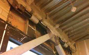
Construction
Many different damper configurations have been used on retrofit projects successfully, each with its own benefits and drawbacks. Horizontal installation (Figure 2) was chosen for this project for its simplicity and to maximize the efficiency of the dampers and lower the damping forces required in the system. The dampers were mounted in pairs in a horizontal position and supported with chevron braced frames. Upper damper mounts were detailed to slide against the beam above using Teflon bearing plates to minimize friction. Existing beams above the dampers were reinforced to support the moments and axial loads generated by the damper mounts. Due to the limited space available while working in an operational building, many of the new beams, columns, and braces had to be delivered in two pieces and spliced together in the field. Installation was complicated by an architectural feature of the original building; perimeter beam lines were set into the building several feet and did not line up with the existing perimeter columns. Because the dampers could not be installed on the interior bays of the building due to the open space requirements of the owner, all of the dampers were installed at the perimeter. To accomplish this, new columns were installed in line with the perimeter beams to resist the vertical damper forces to the existing foundation. The effective installation of the dampers required a significant upgrade to the beams and connections in the collector system. ASCE 41 requires that all of the elements in the damper load path be designed to remain elastic during the design events. The existing connections were single row bolted shear tabs and did not have sufficient capacity to resist the loads from the dampers. In order to upgrade them, tie plates were welded to the beam web and supporting column or beam (Figure
3). These tie plates were designed to carry the entire collector design load, leaving the original connection to resist shear. These tie plates were located as close to the centerline of the beam as possible to minimize the potential effects of added rotational restraint. The collector beams were also refitted with added plate, tee, and HSS sections to improve their compressive capacity. Because the dampers were installed on the perimeter of the building, in some locations the existing diaphragm was not capable of transferring the load between the dampers and the existing drag system on the interior column lines. In several locations, HSS bracing was installed to transfer these loads directly. At several locations, the uplift from the dampers was enough to overcome the dead load ballast in the existing column. This presented the challenge of adding uplift capacity to a pile cap system designed for gravity-loads only. The solution was to add deep micropile anchors on either side of the pile cap. The column loads were delivered to the micropiles using sloped anchor rods stabilized by a compressive strut through the existing pile cap. Steel had to be moved and installed by hand due to the limited space and access in the operational building (Figure 4). In many cases, the welding involved had to be performed in extremely tight quarters. Often, details were reworked on the fly by the structural engineer in order to allow the contractor to complete the work. These collector retrofits, and the difficulty in building them, represented the vast majority of the complexity in the construction of the retrofit.
Conclusion
Through the use of viscous dampers, the owner was able to extend the life of a profitable store for years to come. The retrofit successfully satisfied the owner’s requirement to retrofit the building cost effectively and with minimal impact to the operation of the store. With the unique ability to lower both seismic drift and force demands, viscous dampers are an ideal system to retrofit existing pre-Northridge moment frame buildings. This and similar systems provide an economic method to extend the useful life and significantly improve the safety of these buildings throughout the region.▪ Bill Williams, P.E., S.E. is a Senior Engineer at Coffman Engineers. He can be reached at Williams@Coffman.com. Arvind Nerurkar, P.E., S.E. is a Principal at Coffman Engineers. He can be reached at Nerurkar@Coffman.com.
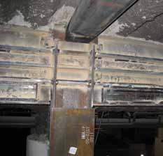
Figure 3: Typical drag retrofit connection.
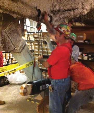
Figure 4: Installation of the viscous dampers by hand. Each damper weighs 500 pounds.
Project Team
Structural Engineer of Record: Coffman Engineers, Seattle, WA Owner: Nordstrom Inc., Seattle, WA Architect of Record: Callison, Seattle, WA General Contractor: Pacific National Group, Los Angeles, CA Viscous Damper Manufacturer: Taylor Devices, North Tonawanda, NY Steel Fabricator and Erector: Riverton Steel Construction, South Gate, CA Software: ETABS Nonlinear V9
Principles for Engineering Education
Part 3
By Eric M. Hines, Ph.D., P.E.
In the previous two articles (STRUCTURE® magazine April 2012 and June 2012), I discussed four principles that are critical for improving the “technical and practical quality of education for structural engineering students.” 1) Theory and practice are indivisible. 2) Engineering is a creative discipline. 3) Drawing is the language of the engineer. 4) There is more than one way to model every problem. In this final article, I continue my discussion in the context of my Junior level course Steel Design at Tufts University, and I will offer conclusions for the entire series. My students arrive swimming in tools that are so sophisticated, they don’t even recognize them as tools. It is my responsibility to narrow the field. Steel Design restricts students to pencil, paper, scale and calculator. Restricting the tools allowed in Steel Design and explaining this philosophically over the course of several weeks helps students understand a type of imagination that is unique to engineers. For instance, I teach my students how to bound a problem. Bounding a problem not only presents an immediate conservative solution, but it also allows an engineer to judge whether further investigation will lead to improvement of the design. We don’t keep our work simple because we are stupid or lazy, we keep it simple because we are sophisticated. Simple work can be checked. It can be
The easiest to use software for calculating wind, seismic, snow and other loadings for IBC, ASCE7, and all state codes based on these codes ($195.00). Tilt-up Concrete Wall Panels ($95.00). Floor Vibration for Steel Beams and Joists ($100.00). Concrete beams with torsion ($45.00).
Demos at: www.struware.com The purpose of design in university engineering education is not to expose students to all the problems they will see in practice, and it is certainly not to teach them how to use the code.
communicated, and it can be mulled over in one’s subconscious. Flashes of inspiration in the shower and sleepless nights are only helpful to those who understand what they are doing. Prior to the rise of computational analysis, the nature of hand calculations was twofold – developing a process and an answer. The purpose of hand calculations now has shifted more toward process. Engineering calculations are a form of communication. And ultimately, they are a record of an engineer’s thoughts – right, wrong or indifferent. In my practice, I have learned that remembering the process by which I arrived at an answer is as important to me as having the answer itself on record. I tell my students that we probably differ in terms of how we approach our mistakes. They somehow believe that a wrong answer reflects their lack of intelligence. I know that a wrong answer is an inevitable result of my humanity, so I have to work according to a discipline that will allow me and my colleagues to catch my mistakes. Clear communication of my thought process is fundamental to this discipline.
Steel Design requires 4 contact hours per week, with two 75 minute lectures and one 75 minute studio run by a practicing professional appointed for one semester as an “Engineering Fellow”. The course proceeds in three phases.
Phase I introduces the language of steel design, and therein introduces students to relationships between systems and details. These relationships form the heart of engineering design. This phase aims to provide students with the basic vocabulary and grammar for expressing structural ideas in steel. It is appropriate to design a whole building, but it is also appropriate to use only the most simplified loads and analytical methods. The level of design is conceptual, the kind students may practice in 10 years, but the drawings and details produced are real and could be used as the basis for construction. The object is not for students to hit the ground running when they start work, but rather to help them understand how calculations, member selection methods and codes are at the service of drawings. The work produced during Phase I over the course of four to five weeks forms the basis from which detailed analyses and construction documents could be executed if there were time. Phase II creates a space of approximately four weeks to review fundamental principles and engineering methods that facilitate creative thought in structural design. Students begin to develop an understanding of modeling – the act of approximating reality with calculations. Emphasis is placed on comparing approximate and exact solutions along with the nature of the approximations and exactness. Finally in Phase II, the importance of drawing is extended from representation of physical objects in Phase I to the representation of conceptual objects. Students’ understanding of drawing as a language, possessing similar richness to words and mathematics, is deepened in preparation for their work in Phase III. In recent years, Phase III has consisted of two design assignments related to my current work. Assignments are stated in a few lines, and provide the context for countless design solutions. Lectures discuss my work on these and other projects, with particular emphasis on my design process. Student work is evaluated during Phase III in a studio environment, where students pin-up and explain their work to classmates, professors and Engineering Fellows.
Conclusion
About three years ago, I reached a turning point in my teaching. I had become disillusioned, wondering if I was ever going to produce work that could be expressed in textbook problems. Every real problem, no matter how simple, needed some context in order for its reality to make sense. I eventually realized that my professional work would defy the textbook format for the rest of my career. Reality is messy. I decided that it wasn’t my work that was fl awed so much as it was the textbooks. Textbooks deliver example problems in step-by-step format – and teach students to look for the steps as opposed to thinking for themselves. Textbook problems are nicely typed and give the impression that whoever solved them made no mistakes along the way. My point here is that I had to gather up some courage in order to take reality seriously – and it has greatly benefi ted my teaching. What should engineers learn in school and what should they learn on the job? Clearly, work exposes people to hundreds of problems. Th e question is whether these problems get integrated into a conceptual framework that sees them as variations on a few important themes. When the framework is not intact, it is more likely that these experiences continue to appear literally as hundreds of problems. Th e National Research Council highlighted the relationship between this conceptual structure and the essence of expertise in their landmark treatise How People Learn. Th e frequency with which my senior colleagues relate stories about their own undergraduate years emphasizes the persistent power and meaning of their education as the foundation for their practice. Th e purpose of design in university engineering education is not to expose students to all the problems they will see in practice, and it is certainly not to teach them how to use the code. Rather, design classes ought to motivate and challenge students’ fundamental understanding in the context of a creative process. Th e relationship between theory and practice is so strong that the two cannot be separated without
ADVERTISEMENT - For Advertiser Information, visit www.STRUCTUREmag.org doing violence to reality – which itself is a unity – no matter how messy it may be. Not all real-world problems are appropriate for educational purposes. And, simple examples which illustrate a theory as well as they refl ect reality are rare indeed. It is a wonder, therefore, that the development of high quality examples for teaching is not an intellectual discipline in its own right.▪ Eric M. Hines, Ph.D., P.E. is a Principal at LeMessurier Consultants, Inc. and Professor of Practice, Department of Civil and Environmental Engineering, Tufts University. Dr. Hines specializes in the design and renovation of building structures, renewable energy infrastructure, and the seismic performance of bridges. In 2011 he received the Henry and Madeline Fischer Award, recognizing him as “Engineering’s Teacher of the Year” at Tufts; and in 2012 he received the Designer Special Achievement Award from the American Institute of Steel Construction. He can be reached at ehines@lemessurier.com.
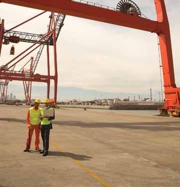


William Hubert Burr
By Frank Griggs, Jr., Dist. M. ASCE, D. Eng., P.E., P.L.S.
William Hubert Burr was widely known as a Professor of Civil Engineering at Columbia University, New York, and internationally known as a Consulting Engineer and one of the greatest bridge engineers of the post civil war period. He was born in Watertown, Connecticut, July 14, 1851. He attended the Watertown Academy and then entered a four-year program at Rensselaer Polytechnic Institute (RPI), Troy, NY. He graduated in a class of 17 students in 1872 with a degree of Civil Engineer. In 1872, he went to work for the Philipsburg Manufacturing Company in Philipsburg, New Jersey that had recently moved into the bridge building field with Alfred P. Boller, RPI ’61. After a promising start, the firm went bankrupt in 1874 and Burr went to work for the City Water-Works of Newark, NJ, for part of one year. In the following year, he returned to Rensselaer as an Instructor in Mechanics. In l876, he was appointed Professor of Rational and Technical Mechanics and served in that position until 1884. His bridge building career began anew when he was appointed Assistant to the Chief Engineer of the Phoenix Bridge Company, Aldolphus Bonzano. Phoenix Bridge was the successor to Clark, Reeves and Company that ceased operations when Thomas C. Clarke left the firm. The President of the firm was David Reeves, Burr’s classmate at RPI. William Reeves, RPI class of ’73, was also an officer in the parent company, the Phoenix Iron Works. Working with Adolphus Bonzano, Burr designed, or detailed the design of other engineers, and fabricated and erected some major bridges in the United States, including the Chesapeake and Ohio Railroad Railroad Bridge across the Ohio River at Cincinnati, Ohio, then the heaviest truss bridge in existence; the Louisville & Jeffersonville bridge across the Ohio River; the Red Rock cantilever bridge across the Colorado River near Needles, Cal., designed by J. A. L. Waddell, (RPI ’75); and, the Pecos viaduct in southwestern Texas, then the highest viaduct structure in the country. He left Phoenix Bridge in 1891, when work slowed, and returned to New York City to become President of Sooysmith and Company, one of the early firms specializing in foundation design and construction. Sooysmith, a General in the Civil War, had a son by the same name who graduated from RPI in 1872, the same year as Burr, who was running the company at the time. He stayed with Sooysmith for one year and returned to engineering education as a Professor of Civil Engineering at the Lawrence Scientific School at Harvard University. In 1893, he became a Professor of Civil Engineering at Columbia University in New York City. Burr remained at Columbia until 1916, but his appointment evidently permitted him to maintain an extensive consulting practice with offices in New York City. His first consulting position was on two swing bridges across the Harlem River, on which Alfred P. Boller, his mentor from the Philipsburg Manufacturing Company was the chief engineer. They were the Harlem Ship Channel Bridge and the 145th Street Bridge. He was successively consultant to the Department of Public Works 1893-1895, the Department of Parks 1895-1897, the Department of Docks 1895-1897 and the Department of Bridges 1897-1903. In 1897, he entered a competition to design the Arlington Bridge across the Potomac River at Washington, DC. Designs were also submitted by Leffert L. Buck, George Morison, and William Hutton. Burr proposed three designs, the third of which had six segmental concrete (Melan) arch spans of 192 feet, a double leaf bascule draw span with a clear opening of William H. Burr 1851-1935. 159 feet and 27 masonry arches with spans of 60 feet. The total length of bridge was 3,400 feet. The long concrete arches consisted of five ribs with the exterior faces being covered with granite. The commission accepted Burr’s design, but bridge work did not begin on the bridge until 1926. It opened in 1932. In 1894, Burr was appointed to a committee by President Cleveland to determine whether a proposed bridge across the Hudson River should be a 2,400-foot span cantilever with piers in the river or a 3,200-foot span suspension bridge. The committee recommended the suspension bridge, but such a bridge, the George Washington bridge, was not built until 1931. While still teaching and serving as consultant to New York City, he was appointed by President McKinley in 1899 to a Board investigating the proposed route for a canal to connect the Atlantic and Pacific Oceans. He was a member of the majority, George S. Morison being the minority, which selected the Nicaragua Route. The committee later recommended the Panama Route. In 1902, he was appointed by President Theodore Roosevelt to determine whether a sea level or lock canal was the best solution. He recommended a sea-level canal, but Roosevelt chose the lock canal that was built later. In 1906, Burr designed the Sandy Hill Reinforced Concrete Bridge across the Hudson River between Saratoga and Washington Counties near Glens Falls. It
Arlington Memorial Bridge. Sandy Hill Bridge.
was a series of 15 concrete arches reinforced with steel arched ribs. In 1908, he submitted a design for the Henry Hudson Memorial Bridge spanning the Spuyten Duyvil Creek that was widened as part of the Harlem Ship Channel. It was another reinforced concrete bridge with a main span of 703 feet, reinforced in a manner similar to his Sandy Hill Bridge. In addition, Burr had been a consultant for the Governor of New York on a study for the New York State Barge Canal, a Consultant on the Holland Tunnel, Member of a Board to locate a deep water port for Los Angles, California, member of a board to review Gustav Lindenthal’s design for the Queensboro (Blackwell’s Island) Cantilever Bridge, Report on the Necessity for the Catskill Water System, a tunnel under the East River, the second Croton Dam, and designer of the Harlem River Speedway and City Island bridge (1901). He was a prolifi c writer, with seven books written between 1886 and 1913. In addition, he wrote many articles in the professional literature of his day. He was awarded the Th omas Rowland Fitch award in 1891 and the Order of the Sacred Treasure by the government of Japan. His Memoir in the Transactions ASCE stated, “Although he possessed to an almost uncanny degree that inherent structura1 sense and ability to check and design structures by judgment, on which great engineers of earlier days had to depend so largely, he was a leader in the development and advancement of the present rational, scientifi c technique of design… Professor Burr occupied an outstanding position in earlier American engineering education. He stood for the most advanced development of technical theory, and he also was a staunch advocate of the broad and liberal training of the engineer – a training which would enable him to develop into a cultured and useful citizen. In his papers’ on engineering education, written in his characteristically crisp, formal, and forceful manner, he always emphasized the fact that Engineering should be held to a professional parity with the professions of Law and Medicine…and… In fact, there were few major American engineering undertakings of the Twentieth Century in connection with which his approval or advice was not sought.” James Kip Finch, his colleague at Columbia, stated, “With the death of Professor Burr at the Doctors Hospital in New York City on December 13, 1934, the Engineering Profession lost one of the great leaders of an engineering generation whose record of achievement is written in the greatest engineering works the world has ever known.”▪

Proposed Hudson-Fulton Memorial Bridge.
Dr. Griggs specializes in the restoration of historic bridges, having restored many 19th Century cast and wrought iron bridges. He was formerly Director of Historic Bridge Programs for Clough, Harbour & Associates LLP in Albany, NY, and is now an independent Consulting Engineer. Dr. Griggs can be reached at fgriggs@nycap.rr.com.
Plugging Analysis and Design Plugging Analysis and Design into Your 3D Workflow into Your 3D Workfl ow
WITH new processes like BIM (Building Information Modeling) and new project delivery methods like IPD (Integrated Project Delivery), more and more engineering firms are being asked to participate in collaborative, modelbased workflows. Migrating to these new processes can be made easier with software designed to support them— software like Scia Engineer from Nemetschek. Scia Engineer is a new breed of integrated structural design software that goes beyond analysis and helps firms successfully join in today’s 3D workflows.
Fast and Efficient Modeling
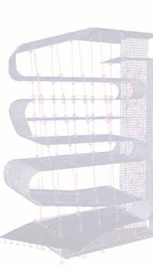
Modeling is an essential requirement for any 3D workflow. As projects become more complex and project timelines compressed, modeling needs to be fast and efficient, but also not restrictive. Engineers need to be able to keep up with the modern designs coming from architects and contractors who push the limits of new materials and methods. “A unique feature of Scia Engineer is its modeling capabilities,” says Mark Flamer, M.I. Flamer & Associates. “It’s a very fast and efficient FEA (Finite Element Analysis) modeling tool. freeform modeling capabilities make it easy for me to work up designs in 3D and keep pace with my architect’s avant-garde designs. And, its parametric object technology has allowed me to automate routine and repetitive work. I can quickly work up and test design concepts. Then, when the design has gelled, I can develop an accurate structural model in Scia Engineer or link my design to another modeling program for coordination and documentation.” With support for open standards like IFC 2x3 and direct links to a number of BIM software programs like Autodesk Revit® Structure & Tekla® Structures, Scia Engineer makes it easier for engineers to reuse models created by others and leverage them into analysis. This is a huge advantage when working in a collaborative workflow. “For the new National Music Centre project in Calgary, Canada, the architect made frequent and sometimes dramatic changes,” says Andrea Hektor, KPFF Portland. “We needed to be able to give them a quick thumbs up or thumbs down on their revised designs. With Scia Engineer it was great. The architects would just send us their updated models. We would import them into Scia Engineer, update our model, run a quick analysis, and give them enough information to continue moving forward. I don’t think we would have been able to do this with any of the other analysis software we have in our office.” Another advantage of Scia Engineer is its extensive functionality. Analysis and design is becoming more rigorous, and owners are looking for highly optimized structures to minimize materials, construction time, and costs. Being able to have one program that is efficient for your day-do-day work, and at the same time offers the ability to handle complex analysis tasks is a big benefit. “With support for non-linear, multi-material design and multiple codes, I’ve avoided having to invest in disparate analysis programs,” says Michael Ajomale, Principal, Design Depictions Structural Engineering, P.C. “Reducing the number of analysis programs we manage saves on maintenance costs and makes it less expensive to train new employees. Most importantly, it reduces the risks that come with manually coordinating multiple analysis models. For occasions when I need to go outside Scia Engineer, I appreciate its ability to integrate my Excel™ checks and its XML support.”
Growing with Technology
In addition, the right software makes a firm more flexible, allowing them to go beyond their usual projects, and take on work wherever they find it. “Scia Engineer allows our firm to confidently compete for bigger building projects as well as go beyond buildings,” says Flamer. “While our expertise is in commercial, we just completed a bridge project and are ready to take on larger, complex structures. A flexible tool like Scia Engineer makes all the difference.” He added: “I evaluated the usual list of structural analysis programs, and there isn’t another program in the market like it. Scia Engineer is the only program I found that integrates fast and efficient modeling, advanced multi-material design, and lets me easily reuse and share 3D models. For us, Scia Engineer was a logical choice.” For information, call 1.877.808.Scia (7242) or visit www.nemetschek-engineering.com
Daniel Monaghan is the U.S. Managing Director of Nemetschek Scia, developers of leading software products for AEC software industry. He can be reached at dmonaghan@scia-online.com When Modeling Matters, Scia Engineer Delivers
“More in tune with the engineer’s workflow”
“Eye-opening”
“Extremely impressed”
Read the AECbytes Article
http://bit.ly/AECbytes
Scia Engineer is a new breed of integrated structural design software that goes beyond analysis to help firms excel in today’s collaborative 3D workflows. Discover fast, efficient modeling and simple FEM analysis. Recycle and leverage models created by others into analysis. And, centralize your design tasks with static and advanced nonlinear multi-material design and multiple codes in ONE program.
See how we can help improve your 3D workflows.
(877) 808-7242
www.nemetschek-engineering.com
Special Section
Engineering Software
Software Makers Bullish on Business

By Larry Kahaner
The consensus among structural software companies and their customers is clear: the construction industry is on its way back from the downturn of the past several years. Until now, companies have been hopeful, even guardedly optimistic about growth. Now, however, rising optimism is being confirmed by an increase in software sales. To meet growing customer needs, software makers are keeping up on codes, adding improvements and allowing users to access software through different media, including smartphones and tablets. At Devco, Software, Inc. (www.devcosoftware.com) in Corvallis, Oregon, President Rob Madsen sees definite business improvement. “We have seen a definite uptick in sales and a more optimistic customer base in the last six to nine months,” he says. To meet customer demand, the company has rolled out LGBEAMER v8 Pro which Madsen describes as “the latest release of our powerful and user friendly design software for cold-formed steel studs, joists, channels and zee’s. In addition to the standard component design modules, LGBEAMER has many useful design modules for framed openings, shearwalls, x-braces, floor joists and rafters. The latest release also includes the 2007 NASPEC (AISI S100-07) which has recently been adopted by most building jurisdictions.” He says that the primary improvement is in the ability to calculate distortional buckling capacity as well as warping torsion as required by current building codes. (See ad on page 46.) Dan Monaghan, Managing Director, North America, Nemetschek Scia (www.scia-online.com) in Columbia, Maryland is also witnessing improved conditions. “Overall, the business outlook from the firms we are talking with are more positive than last year,” he says. “The trend towards Building Information Modeling continues to be a driving force for the adoption of software. Most firms who jumped into BIM early are now recognizing that it’s a process not a technology. They are looking for flexible software that can help them plug analysis and design into as many workflows, and not be forced into using one vendor’s software.” Adds Monaghan: “As a result, we’re seeing more demand for the support of Open BIM standards like IFC (Industrial Foundation Class), a neutral file exchange format, and ISO standards that all BIM software supported. With support for Open BIM, our users can exchange BIM models with any BIM compliant software which gives engineering offices a competitive advantage.” The company recently released Scia Engineer 2012. “While Scia Engineer may be a new brand to some, it has a long development history-over 35 years,” says Monaghan. “This new release represents a milestone in our development history and in the industry. Scia Engineer is now the only integrated structural design software program that links structural modeling, analysis, and multi-material design with support for several international codes, and offers bidirectional drawings and calculation reports in one program. With support for open standards like IFC 2.x3, SDNF, and bi-directional links with Revit Structure and Tekla Structures, Scia Engineer makes it easy for engineers to participate in today’s BIM process. This new release offers some great improvements for day-to-day work including expanded code support for IBC and Eurocodes, and new support for Brazilian codes. It is also the only structural analysis software that offers advanced parametric optimization, which allows engineer’s to set up engineering problems and have the computer run through hundreds, or even thousands, of calculations to help derive an optimal solution that can be checked against codes.” Amber Freund, Director of Marketing for RISA Technologies (www.risa.com) in Foothill Ranch, California echoes the upbeat responses of others. “We are hearing more about new projects and older projects that are being revisited. It’s a slow growth, but I think construction is definitely coming back. Hopefully this time it will be at a more sustainable rate.” To accommodate customers needs, RISA Technologies recently partnered with Tekla to link Tekla Structures

Engineering Software
and RISAConnection. Th is gives engineers the ability to design their connections from within their steel detailing model. RISA will be at the Tekla User’s Group in August demonstrating this new link, according to Freund. “RISA has had the ability to design the connections in the past, but not provide the detail drawings,” she says. “Th is new link with Tekla will allow engineers to both design and detail the connections without having to do any manual data entry or drawing. Engineers were asking RISA how to get detailed fabrication drawings and were asking Tekla how to get connection design. Th e collaboration of the two companies to create this link means engineers can have both the design and fabrication drawings in one model.” (See ad on page 67.) “Sales are up dramatically,” says Engineer and Developer Terry Kubat at IES, Inc. (www.iesweb.com) in Bozeman, Montana. “Th e message we are getting from this is that our customers are not waiting for work; they either have it or believe it will be coming very soon. Many companies put off investments in their productivity tools during the construction crisis, but that crisis is obviously over with IES customers.” Th e company relies on the day-to-day feedback from thousands of customers to fi ne tune its products, according to Kubat. “IES customers are clever engineers who are fed up with software bureaucracy, those products with too much power that force you to relearn your job. IES customers much prefer software that is friendly and fl exible enough for daily tasks. Engineers in all industries and sectors appreciate tools that are simple enough to use without a manual.” He adds: “IES off ers nine products to meet a wide range of needs. We continue to improve on these tools, and in 2012 we are focusing on reliability and stability of our products to help insure a smooth work-fl ow for our customers.” One product is VisualAnalysis 9, “a far more accurate design-platform compared to any previous release,” says Kubat. “We performed automated validation to insure the highest quality of analysis and check results. In addition, we have built-in crash reporting that has allowed us to reduce instability issues by over 1000 percent with no eff ort on the customer’s part.” (See ad on page 48.) Off ering new software is Design Data (www.sds2.com) of Lincoln, Nebraska. “In addition to the rebranding of our entire SDS/2 product line – which now includes SDS/2 Engineering, SDS/2 Erector and SDS/2 BIM – Design Data has launched SDS/2 Connect,” says Doug Evans, Vice President of Sales. “SDS/2 Connect is a new add-in for Autodesk Revit Structure that automatically designs connections within the Revit environment. SDS/2 Connect helps make it possible for structural engineers and fabricators to design, conduct code check analysis, and extend steelwork designs to fabrication within a BIM workfl ow. SDS/2 Connect is the only product that enables structural engineers to design and communicate steel connections based on their Revit Structure design model as an active part of the fabrication process,” he says. Previously, Evans notes, their product was developed for the manufacturer and used in the manufacturer’s offi ce. “Th e recent release of SDS/2 Connect now allows the engineer to use the product in the engineer’s environment. Th is, along with the other modifi cations to the SDS/2 core product line, encourages the model to be used through the lifecycle of the project.” Evans agrees that the business environment has improved and adds, “In all sectors, people are optimistic about the continued future growth.” The recent economic downturn has changed the landscape, according to Heather Johnson, Marketing Manager for StructurePoint, LLC (www.structurepoint.org) in Chicago, Illinois. “Mergers and acquisitions have continued this year to close some doors yet open opportunities in other areas. Th is results in strong support for software assets and heavy licensing activity globally geared towards ensuring engineering access to the latest technology across all operating platforms,” says Johnson, who adds, “We feel very optimistic about the continued on page 48


Engineering Software
steady recovery in North American markets and continuing improvements in the Middle and Far East.” As the Engineering Software Department of the Portland Cement Association since 1960s, StructurePoint specializes and focuses entirely on reinforced concrete buildings and structures. It also serves its end users as the gateway to cement and concrete industry resources, according to Johnson. Th e group has updated its software to refl ect relevant provisions of the ACI 318 code and commentary issued in 2011, and these updates have been incorporated in the software suite and released to the public at the end of 2011. “Taking advantage of the latest provisions in the code allows our end-users to optimize their design and arrive at the maximum level of reliability and economy for their structures,” says Johnson. Also updating their products to meet code requirements is Chicagobased CSC, Inc. (www.cscworld.com). “We specialize in developing code-based structural design solutions,” says Vice President Stuart Broome. “Th is means that rather than adding design post processors on to a frame analysis program, we build our software from the ground up around the requirements of a design code, such as AISC360 as in the case of Fastrak.” Fastrak is the company’s steel building design software that works with CSC’s Integrator, a new and free tool for synchronizing Fastrak and Revit Structure models back and forth. Another product is Tedds, a calculation production suite which automates the design and documentation of structural components. “It off ers the best of both worlds: a completely library of calculations, along with powerful functionality for engineers to create their own calculations,” Broome notes. “Th e primary benefi t of Tedds is increased productivity, but many of our clients value the detailed and transparent output which Tedds produces. Tedds works within a Microsoft Word environment ,meaning that most engineers know how to use it before they even open up the software for the fi rst time. Microsoft Word makes it easy to compile full calculation documents including sketches, photos, Autocad and Revit Drawings, contents pages and Excel spread sheets,” he says. (See ad on page 3.) For concrete construction, Bentley Systems, Incorporated (www.bentley.com), based in Exton, Pennsylvania, has introduced ProConcrete, which is software for advanced 2D and 3D parametric modeling, detailing, and scheduling of cast-in-place and precast reinforced concrete structures, now available on MicroStation or AutoCAD, says Huw Roberts, Global Marketing Director–Building and Structural. “ProConcrete provides engineers, detailers, fabricators, constructors, and contractors a strong visual understanding of reinforcement interactions across multiple planes, including clash detection capabilities. By integrating tools and collaborating data across reinforced concrete projects, from design and detailing upstream to fabrication and construction downstream, ProConcrete can reduce documentation production time, construction costs, and project timelines, while eliminating errors and design fl aws,” Roberts says. continued on page 50
ADVERTISEMENT - For Advertiser Information, visit www.STRUCTUREmag.org
Mat foundations and combined footing design made easy
Easy to learn and use Analyze a foundation quickly Model complex geometry IBC, ASCE 7, ACI 318
Visit www.iesweb.com

Download Your Free 30-Day Trial
IES, Inc. | 519 E Babcock St. Bozeman MT 59715 800-707-0816 | info@iesweb.com

Engineering Software
He notes that Bentley has tried to simplify SE’s software choices by off ering interoperability among products. “Structural organizations typically use multiple software packages and tools to do their jobs. Th e challenge is then to get these specialized products to interoperate and avoid ineffi ciencies. Bentley addresses this by off ering its open ISM methodology to facilitate structural interoperability, primarily in the areas of visualization, change management, and revision histories. Bentley off ers ISM free of charge to the structural community. Th e newest version off ers feature additions and subtractions, more new materials, coordination of member end and base reactions, connection tags, and coordinate system transformations.” Keeping its products current and up to code changes is also a priority at S-Frame Software (www.s-frame.com) in Guilford, Connecticut. “Th e latest enhancements of S-FRAME Structural Offi ce R10 focuses on supporting the trend of engineering practice and building codes towards more advanced forms of dynamic analysis, especially for seismic loading, and larger, more complex models, due to more prevalent use of shell fi nite elements and the infl uence of BIM,” says CEO Marinos Stylianou. In March, the company also released S-CALC in North America, a new, full-featured sectional properties calculator for sections of any size, shape or material. “S-CALC off ers all the calculations one would expect from a sectional properties calculator, and some that structural engineers have been desiring for years, including Shear Center, Shear Area, Torsional Constant, and Warping Constant. S-CALC is the fi rst of a series of brand new BIM Components we plan to release that will add structural analysis and design depth to BIM. S-CALC features a modern look and feel, customizable user interface, powerful import/export, unparalleled report generation, a scripting environment for automation and fl awless integration with BIM products,” he says. As for business conditions, Stylianou adds, “Th e energy sector in North America, Canada in particular, has been very good to us in 2012, and we continue to see considerable business growth in Asia. We believe that Europe will off er some unique business opportunities in 2013, and we plan to fully evaluate them.” (See ad on page 4.) At the Canadian Wood Council (www.cwc.ca), a national, non-profi t association located in Ottawa, Ontario, representing manufacturers of Canadian wood products used in construction, their mission is to ensure that building professionals have the information in hand to specify and use wood products in a safe, secure, and code-compliant manner, says Robert Jonkman, Manager, Structural Engineering. “One way we do this is through our wood engineering software, WoodWorks. Separate Canadian and U.S. versions of WoodWorks software are available. For the U.S. version, compatible with the IBC, NDS, SDPWS, and ASCE7, we work closely with the American Wood Council (AWC) to ensure consistency in technical interpretations.” Th e software is available for free for building offi cials, plans examiners, and university and college professors. “Most engineers designing with wood have used WoodWorks Sizer already,” says Jonkman. “Sizer is very popular – our most commonly
used software module – enabling engineers to design beams, columns, studs, and joists using light frame construction as well as heavy construction such as timber, glulam and engineered lumber.” Jonkman considers their most time saving module to be WoodWorks Shearwalls because it allows engineers to very quickly model a building either using an AutoCAD exported fi le as a template or drawing from scratch. “Th e software automatically will calculate the wind pressures and suctions as well as seismic forces, distribute the forces to each level, within each level to each shearline, and within each shearline to each shearwall segment. It does this using both the fl exible and rigid diaphragm distribution methods for both seismic and wind forces. For rigid distribution, Shearwalls uses a either a “capacity” approach or a “stiff ness” approach (using shearwall defl ections) to distribute forces to shearlines and shearwalls. Shearwalls designs both perforated and individual full height wall segment type shearwalls,” Jonkman says. (see ad on page 53.) At Computers & Structures, Inc., in Berkeley, California, (www.csiberkeley.com) Executive Vice President Syed Hasanain says that they have been busy working on new versions of their SAP and ETABS software. “Th e new ETABS product will, hopefully, be out in a month or so. We’ve been working on it for the past eight years. We have products that have served the industry for the past twenty-some years before the earlier versions were in place, and now we want to do something which will be good enough for the industry for the next twenty years.” Hasanain adds: “We have also recently come up with a new product for the bridge industry. It’s called CSI Bridge and is also based on our SAP platform.” As for their customers, some of the feedback is mixed. “I think in the recent past the building industry, especially new construction in the U.S., has not been doing well, but we’ve seen a huge increase, as far as sales are concerned, from the bridge industry. We’ve seen big markets created in India and China.” (See ad on page 60.) “As market conditions improve, our customers are seeing incremental improvements to their business,” says Paul McEntee, Engineering R&D Manager at Pleasanton, California-based Simpson Strong-Tie (www.strongtie.com), which manufactures connector products for the construction industry that cover a broad range of residential, commercial, industrial and infrastructure projects. Strong-Tie’s customers include contractors, builders, distributors and homeowners. Th ey also off er technical support, training and service for engineers, architects, building offi cials and other design professionals. In the software area, they are focusing on serving customers’ needs with web and mobile applications to help them get their work done more effi ciently “without being tied to their desk,” says McEntee. continued on page 52


