76 minute read
STRUCTURAL PERFORMANCE
performance issues relative to extreme events
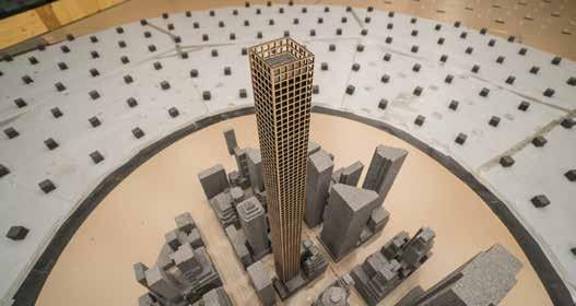
Modern engineering tools and techniques enable structural engineers to continually redefine the limits of possibility. Nowhere is this more evident than in supertall buildings, where controlling wind-induced sway has become a critical aspect of project success. The use of tuned mass damping systems has become a mainstay in attaining this control, in large part because each custom-designed system can be tuned to match the as-built characteristics of the building. They also provide a much more efficient solution than adding more mass or stiffness. One recent example is the Shanghai Tower which, when it opened in 2014, became China’s tallest building and the second tallest building in the world. Even though the design of the 2,073-foot (632-meter) tower was optimized to reduce wind effects, the developer also chose to include a tuned mass damper (TMD) to reduce acceleraFeeling at Home in tions further and eliminate any feeling of structural movement. The resulting 1,100-ton system is the world’s largest the Clouds eddy current TMD, discussed in more detail below.
By Trevor Haskett, P.Eng. and Andy Smith, P.Eng.
Problems
as partitions, glazing, and the façade. Beyond any noticeable harm caused by a single large displacement, the accumulation of many cycles of amplitude can also cause fatigue failures. Wind-induced movement can cause two other significant problems that affect a building’s usability. The first, audible creaking and groaning, seems to be especially prevalent where there is the greatest amount of relative motion between building parts as the building deflects. Often occurring on the lower levels, these potentially loud noises can make even a new building sound like a rickety old ship. The most common problem, however, is the perception of movement that comes from the acceleration of the building as it sways back and forth. This is an issue that designers must address to ensure occupants remain comfortable even as the building moves. Although their homes can be literally in the clouds, people want to feel like they are on solid ground. The inherently low structural damping in modern high-rise structures is a significant factor in managing occupant perceptions of movement. The challenge is made even more problematic because of the relatively high uncertainty in assuming an appropriate level of inherent structural damping.
Trevor Haskett is the Senior Technical Director and Principal and leads RWDI’s team that works on structural vibration and tuned mass damper projects. Andy Smith is the Engineering Leader of mechanical design for RWDI’s tuned mass damper projects. As buildings are designed to be taller and more slender, they also are designed to be lighter and, relatively speaking, not as stiff. As a result, wind tends to cause much more flexure in these structures than in shorter, more squat buildings. To put it another way, the taller and more slender a modern building is, the more lively it is likely to be. If left uncontrolled, excessive wind-induced building movement can cause various problems. For example, large oscillatory displacements may make it necessary to reduce the speed of elevators during strong wind events. Displacements can also damage more brittle secondary elements such
Challenges
Adding movement criteria to the building design process increases the complexity of coming up with a good design. Fortunately, a structure’s dynamic characteristics can be estimated using the structural engineer’s computer model through a back-and-forth approach. Many years ago, wind tunnel testing on an instrumented flexure was used principally to come up with foundation loads to determine the building’s overturning moment. However,
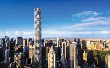
Located within blocks of New York’s Central Park, 432 Park Avenue is more than twice the height of any of its nearby neighbors, leaving the upper portion of the structure fully exposed to the wind. Two 660-ton opposed pendulum tuned mass dampers (TMDs), located near the top of the tower on the east and west sides of the core, provide supplemental damping for 432 Park Avenue.
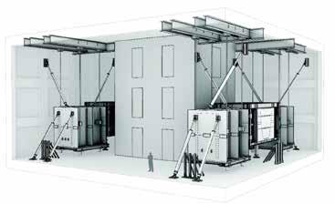
in more recent times, it was realized that the test data already being collected could also be used to estimate accelerations. This is now a routine activity. For many current projects, the structural engineer begins by laying out the structural system to resist the gravity loads vertically and the wind loads laterally – and sometimes earthquake loads, as applicable – based on the selected primary structural materials (which is to say concrete and steel) and their configuration. This initial layout includes the lion’s share of what determines the building’s mass and stiffness. This typically leads to an initial design based on a finite element model. The output from that model provides the dynamic characteristics of the building. Using that information coupled with wind tunnel data and analysis, the structural engineer is given a set of equivalent distributed static wind loads, based on the specific dynamic characteristics of the building and local meteorological climate. This data can be put back into the same finite element model to confirm the adequacy of all structural members for the ultimate design. Another check is conducted to ensure serviceability requirements are met during regularly occurring wind events. All of the secondary members in buildings – everything from the glazing to the interior drywall and partitions – also contribute to building stiffness in minor ways, but these additions are not taken into consideration by the structural engineer, making the findings a bit conservative with regard to safety. Conventional thinking is that, as far as loads are concerned, more stiffness is almost always better. Researchers have gleaned a significant amount of data on building performance characteristics, including damping ratios as a function of height and building type. These characteristics help to estimate structural performance. However, data is less prevalent for a supertall building’s inherent damping except to know that it is going to be very low. In fact, the trend is that the typical amount of inherent damping is decreasing in new buildings as designs get leaner and more efficient, which brings us back to the observation that new buildings tend to be more lively. So, what are the implications when you know you cannot expect much damping from the building structure, but you are going to reach for the sky anyway?
Setting Limits
How people feel about perceived movement and acceleration is highly subjective, so trying to define how much acceleration is too much yields only a fuzzy threshold. However, there is a consensus that building occupancy type and anticipated return periods (or mean recurrence intervals) factor into setting a reasonable range of such limits. Residential buildings have tighter limits on movement than other buildings, such as offices or commercial space. People in a condominium or apartment are going to be much more particular about how comfortable their residence is, on an aroundthe-clock-basis, than the same people would be in an office building. When acceleration guidelines for buildings are set, they also include an anticipated recurrence interval. For example, larger accelerations that the majority of people would sense might be acceptable if they occur only infrequently, such as once a year or once every 10 years. For weekly or monthly occurrences, however, the acceleration would be limited to
a much smaller value that ideally should be imperceptible to most people. Traditionally, the industry has found that keeping residential building accelerations below about 18 milli-g for the worst storm expected only once every 10 years heads off most complaints. For office towers, accelerations of 25 milli-g might be acceptable. That means, essentially, that weather patterns could be expected to produce building swaying that would be noticeable and uncomfortable on the uppermost floors – causing chandeliers or draperies to move, or doors to swing on their hinges – once in 10 years. Although 10-year acceleration targets have proven to be useful guideposts for designers over the years, here again the liveliness of newer buildings comes into play. Whereas, for older buildings, most plots of peak acceleration versus average time between occurrences typically had roughly the same slope, such plots for lighter, more flexible structures can have much flatter slopes. In these cases, it is not unusual for the 1-month and 1-year accelerations to govern. Further complicating the picture, the cyclic frequency of the building’s sway also affects occupant sensitivity. One level of acceleration that is acceptable on a very slow swaying, lowfrequency building may be objectionable on a higher frequency building. This type of limit is reflected in the International Standards Organization’s standard ISO 10137: 2007, which provides acceleration criteria for residential and office structures at the 1-year return period across a range of frequencies. By aligning these limits with logarithmic graphs showing a building’s total peak accelerations plotted against the typical mean time between NOTE – The accelerations experienced in a swaying building are most frequently expressed in thousandths of a G, the constant acceleration due to gravity, which is 9.81 meters per second squared. Applying the metric prefix milli yields the term milli-g.
these occurrences, when and to what extent structural performance improvements are necessary can be determined. (This is a very simplistic description of the process, as several key assumptions go into the actual plot generation.)
Resisting Wind Loads
The process of determining appropriate wind loads for tall and supertall buildings is quite complex. It involves historical weather data, usually from a nearby airport, which may require interpretation to be more site-specific. Further extrapolation is necessary because weather data typically are collected close to the ground. The most critical wind speeds for a supertall building occur several hundred yards above the ground surface. When determining how much a high-rise building will oscillate in the wind, the controlling factor is damping. At one extreme, there is little or no resistance to oscillation and the building continues to sway back and forth indefinitely, unable to dissipate the energy that the wind transferred into it. The opposite behavior, known as critical damping, results in no oscillation at all, and the building simply returns to its at-rest position after any perturbation, in the shortest interval of time. Neither of these is the case in real-world tall buildings. The amount of damping inherent in a tall or supertall building is impossible to predict with any certainty. In fact, inherent damping is the most uncertain structural variable. It, therefore, requires significant judgment and should be viewed together with other material behavior design assumptions. Observed damping ratios for scores of buildings confirm that the damping is very low, and trends lower with every story closer to the sky. A range of inherent damping, typically from 1% to 2% of critical, is used in the design. It turns out that the challenge of designing a building to stay below specific acceleration targets is very sensitive to the as-built damping level in the structure, and that is not known until the building has been constructed. By way of example, if the assumption is 1.5%, it could easily be as high as 1.8% or as low as 1.2%. That sounds like an insignificant absolute difference, but it can make a 20% relative difference in the acceleration levels. Instead of the target 18 milli-g at a 10-year return period, it could end up being as high as 22 milli-g or as low as 14.5 millig, which is quite a wide range of response. So, even though it is understood that the damping levels are low, the uncertainty in predicting real-world accelerations is still very significant. This essential uncertainty concerning a structure’s damping characteristics can be greatly reduced with the addition of a tuned mass damping system. Engineered to operate passively in response to building movement, these types of damping systems exert forces opposing the building’s movement. A TMD system should be as high up in the building as possible to be most effective. Most damping systems are designed to be adjusted, or tuned, once the building is substantially complete to accommodate the uncertainty of the structure’s as-built sway frequency(ies). These TMDs consist primarily of a large mass, either liquid or solid, some means of dissipating the energy, and an appropriate system of attachment to the structure. The mass is specifically sized for each building according to the demand for improved performance; for supertall buildings, this is typically several hundred tons. Liquid dampers use a mass of moving water in various configurations, including tuned liquid column dampers and tuned sloshing dampers. Although water dampers are usually somewhat less expensive than their solid counterparts, they take more space and are not as high performance per ton of installed mass. Solid TMDs usually consist of multiple steel plates that are transported to the TMD location and assembled in place. The mass can be suspended by cables, much like a simple pendulum, or supported by other low friction means. Other configurations in common use include a dual-stage pendulum, which requires only about half the vertical clearance, and an arrangement of opposing pendulums. In the latter case, one mass held aloft by struts is linked to a second mass supported pendulum-style. This configuration can be used to create a long period set up in the relatively low headspace. After the building is structurally complete, the TMD must undergo a tuning and commissioning phase. With the TMD locked out, the final as-built frequency of the building must be measured. The TMD is then tuned to best interact with that frequency and release it to do its work of steadying the tower, keeping even its highest occupants feeling as stable and sure-footed as if they were on solid ground.
TMDs at Work
Selecting a specific type of TMD for a given building is accomplished through an implementation assessment. Primary considerations include the force required and space constraints, although other factors also come into play. 432 Park Avenue This slender, taller-than-all-neighbors residential tower in the heart of New York City offered an extreme challenge in managing wind effects. Despite extensive attempts to reduce wind effects through reshaping, which led to including wind floors at several levels of the structure, the need for a supplemental damping system was a foregone conclusion. The building’s long period, together with the required large movement of the damper mass, eliminated sloshing damper technology from consideration. To meet the space constraints, two 660-ton opposedpendulum TMDs, one on each side of the building core, were ultimately used. Shanghai Tower This tower was one of those rare cases with accelerations below the ISO standards to
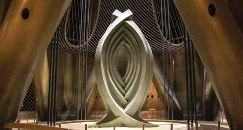
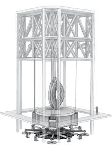

Supported by the crown structure of the tower, the simple pendulum of the tuned mass damper at the top of the Shanghai Tower is suspended over an eddy current damping system by 12 cables, three on each of four corners.
begin with, but the owner wanted them to be even lower – and was prepared to spend significantly more to achieve that. The goal was to give the impression that the structure simply does not move. That led to the installation of a 1,100ton TMD, which the owner also wanted to display as an architectural feature visible within the observation levels. Also, a unique form of damping was added to the system. Typically, TMDs have sizeable viscous damping devices (VDDs), similar to shock absorbers, which are used to drain energy from the TMD and also control its response in high winds. For the Shanghai Tower, a large array of rare earth magnets was attached to the pendulum, and a layer of copper plate was fixed to the floor. As the TMD travels back and forth, electrical eddy currents are passively formed that create a force that resists the motion of the pendulum mass relative to the tower. This system replaced the eight large, inclined VDDs that otherwise would have been used, making the installation much more aesthetically pleasing. This installation is the world’s largest eddy current TMD.
Conclusion
Supplemental damping technology is something that should be in every tall building designer’s toolbox. Especially when used in conjunction with shaping techniques that reduce wind effects, TMDs can make living and working in high-rise buildings every bit as comfortable as more traditional, shorter buildings. And that allows people to relax and enjoy the spectacular view.▪
MAKING NEW AND EXISTING STRUCTURES STRONGER AND LAST LONGER
INNOVATIVE PRODUCTS
STRUCTURAL TECHNOLOGIES’ V-Wrap™ FRP is a lightweight, high-strength, code approved composite system for concrete and masonry structures and structural elements. These lightweight, high-strength materials are used to restore and upgrade load-carrying capacity.
PERFORMANCE
• Long-term durability • ICC-ES approved • UL-approved fire-resistant finishes available
FLEXIBLE AND EFFICIENT
• Utilized on a variety of structural elements • Ideal for complex geometries • Result in faster schedule and cost savings
RELIABLE SUPPORT
STRUCTURAL TECHNOLOGIES combines comprehensive, no-cost, technical support from industry experts with extensive and relevant structural engineering experience, including expertise in seismic applications.
EXPERTISE
• Product selection • Specifications • Preliminary design • Construction budgets
Our Strengthening Solution Builders ensure V-Wrap™ systems are engineered to meet a project’s specific requirements with components that optimize application performance. Quality you can trust from a rock solid team you can rely on.
www.structuraltechnologies.com | 410-859-6539
Historic structures
significant structures of the past
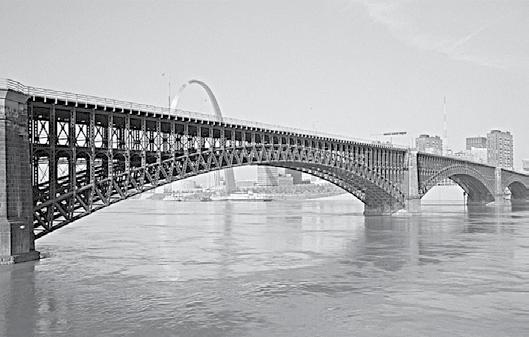
The Eads Bridge was, perhaps, the best-known bridge of the 19th century after the Brooklyn Bridge. A bridge across the Mississippi River had been projected as early as 1839 when Charles Ellet Jr. (STRUCTURE, October 2006) proposed a 1,200-foot span suspension bridge. John A. Roebling (STRUCTURE, November 2006) also proposed a hybrid bridge, with a pier at midriver, a short time later. The St. Louis and Illinois Bridge Company was formed in 1855, but nothing was done until February 1864 when the State of Missouri granted a charter. James B. Eads was named Chief Engineer on March 23, 1867, after he submitted preliminary plans in early March. By May 1867, Eads decided to build his bridge as a three-span arch bridge over the Mississippi River with the arches made of steel. To assist him, the Company named Jacob Hays Linville (STRUCTURE, July 2007) of the Pennsylvania Railroad and Keystone Bridge Company as a Eads Bridge at St. Louis consulting engineer. The design was based on a bridge across the Rhine River at Koblenz By Frank Griggs, Jr., Dist. (Coblenz), Prussia. M.ASCE, D.Eng., P.E., P.L.S. Eads first design had a central span of 515 feet and two flanking arches of 497 feet, with a minimum clearance of 50 feet above high water. He recruited Henry Flad, Charles Pfeifer, and W. Milnor Roberts as his assistant engineers. When Eads made his design known to the public in 1867, the St. Louis Democrat wrote, “What a triumph for St. Louis, the noblest river, the most glorious bridge, and the finest engineer in the world. His arch ribs were to be made of steel in the form of steel tubes in straight pieces connected together to form a polygon of 800 sides.” Upper and lower arches were to be connected by trussing, and the arches were to be fixed at the ends making them statically indeterminate. The easterly approach in Illinois consisted of a long iron viaduct with masonry arches flanking the end spans of his arches. Railroad tracks were on the lower deck, and roadways and pedestrian walkways on the upper deck. In the meantime, Lucius Boomer was also proposing a bridge in the same area under the name of the Illinois and St. Louis Bridge Company. He had Simeon Post work out a design consisting of six wrought iron Post Trusses with two spans of 368 feet and four of 264 feet. To promote his plan, Boomer called a convention of engineers to look over all plans but with special attention to his plan. The Convention favored Boomer’s plan and recommended in their Report spans of no more than 350 feet. Eads went on the offensive and responded with “If there were no engineering precedent for 500-feet (stet) spans, can it be possible that our knowledge of the science of engineering is so limited as not to teach us whether such plans are safe and practicable? Must we admit that because a thing never has been done, it never can be, when our knowledge and judgment assure us that it is entirely practicable? This shallow reasoning would have defeated the laying of the Atlantic Cable, the spanning of the Menai Straits, the conversion of Harlem Lake into a garden, and left the terrors of the Eddystone without their warning light. The Rhine and the sea would still be alternately claiming dominion over one-half of the territory of a powerful kingdom, if this miserable argument had been suffered to prevail against men who knew, without ‘an engineering precedent,’ that the river could be controlled,
Dr. Frank Griggs, Jr. specializes in the restoration of historic bridges having restored many 19th Century cast and wrought iron bridges. He is a Professor Emeritus of Civil Engineering at Merrimack College in N. Andover, Massachusetts and is currently an independent consulting engineer. Dr. Griggs can be reached at fgriggsjr@twc.com.
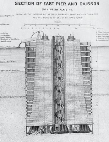
East pier caisson. and a curb put upon the ocean itself.” The two bridge companies later merged.
When Linville saw the preliminary design, he wrote, “The bridge if built upon these plans will not stand up; it will not carry its own weight… I cannot consent to imperil my reputation by appearing to encourage or approve its adoption. I deem it entirely unsafe and impracticable, as well as in fault in the qualities of durability.” Linville later, as Chief Engineer of the Keystone Bridge Company, would be in charge of building the superstructure of the bridge.
When making a case for his bridge, Eads told his investors that he could build the bridge for $3,000,000 and have it opened for traffic within 3 years. He had never built a bridge before, especially a bridge that was going to have a great deal of steel in it. Steel was used for many years, but not in bridge building or major building construction. Wrought iron by this time had generally replaced cast iron and wood in bridge construction, with much of the progress attributable to Linville and the Keystone Bridge Company plus the Phoenix Bridge Company, the Detroit Bridge Company, and others.
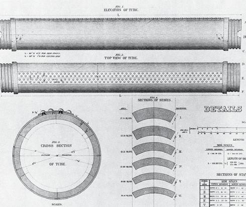
His first construction task was to place foundations for his two river piers and two abutments. Given his knowledge of the shifting sands of the the arches in bars of 9 feet length, and of such Mississippi River bed, form that ten of them shall fill the circumferhe insisted his founda- ence of a 9-inch lap-welded tube one-eighth tions rested on bedrock inch thick, in the manner that the staves of and looked at various a barrel fill the hoops. This would virtually methods to accomplish form a steel tube 9 inches in diameter and of this. Bedrock on the west 6 inches bore, the steel being about 1½ inches abutment was near the thick, and would be much less expensive than surface, so it presented if the tube were rolled or drawn in one piece. no problems. His east The manufacture of the steel in such small and west piers, however, bars will ensure a more uniform quality in the would have to be sunk to metal, and in the tube each bar will be supdepths of 95 feet and 86 ported against deflection in every direction. feet below the river sur- The tubes will be retained in their positions face. His east abutment by an effective system of bracing, which will would have to reach a sustain the voussoirs or pieces against which depth of 110 feet. the tubes are butted throughout the arch... Eads learned about The tubing in which the steel bars will be pneumatic caissons on enclosed will effectually protect the latter from a trip to Europe. Even the weather.” though no one had ever His tubes were made of steel staves covered used them at the depths with a steel casing similar to wooden barrels. required at St. Louis, he The length of staves varied, as did the thickdecided they were the ness. Eads had to compromise his original only possible means to specifications. He had significant problems reach bedrock. While in getting the quality steel he wanted for placing the foundations, the staves as well as for the couplings that 14 men were lost, mostly connected the tubes. Once the staves were on the west pier, to what encased, he had to mill the ends to ensure was to become known as full bearing from one set of staves to the next. caisson’s disease or the bends. By May 1870, all of the foundations were in place, and Eads could begin erecting his superstructure. His original arches were doubled steel tubes, top and bottom, with diameters of nine inches. He later changed this to single tubes with 12-inch diameters, and even later to diameters of 18 inches. He also changed the vertical spacing between the top and bottom tubes from 8 to 12 feet, as well as having the lower arch come up tangent to the deck chords of the railroad tracks. The spans were revised to 520 feet on the center span and 502 feet on the flanking spans. Transversely, the two center arches would be 13 feet 9½ inches apart and the outer arches 15 feet 1¾ inches off the center arches. He knew the uniqueness of his use of steel and in 1867 wrote: “To ensure a uniform quality and high grade of steel at the lowest prices, and at the same time avail myself of the advantages of the tubular form of construction, I propose to have the steel rolled for Coupling and pin to connect diagonals to tubes.
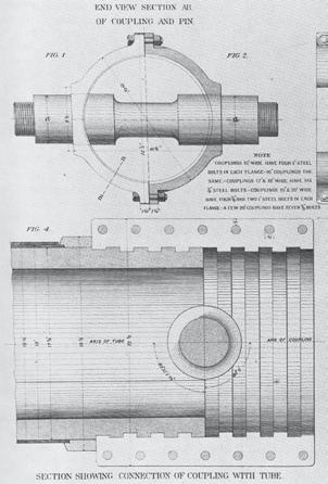
He also had to cut-in the threads to receive the couplings. He retained Theodore Cooper (STRUCTURE, April 2011) to handle the fabrication of the staves and couplings. Cooper was later in charge of the erection of the tubes. Since falsework could not be placed in the river, Eads developed a way to build the superstructure by cantilever methods. He, Flad, and the Keystone Bridge Company erected wooden towers on the piers and abutments and ran links down to the arch segments to support them before the closing of the arches. He had major problems in fitting his final arch segments (the equivalent to a keystone) and had to modify them by making them adjustable. The bridge was opened to pedestrians on May 24, 1874. The first train crossed on June 9, and it was test loaded on July 2. It was formally dedicated on July 4, 1874, with a grand celebration. Eads, in his speech, stated, in part: “The love of praise is, I believe, common to all men, and whether it be a frailty or a virtue, I plead no exemption from its fascination. The wish to merit the good opinion of our fellow-citizens, and especially of those whom we respect and esteem, is a laudable stimulus to effort…Yon graceful forms of stone and steel, which prompt this wonderful display, stand forth, not as the result of one man’s talents, but as the crystallized thought of many, aye, very many minds, and as the enduring evidence of the toil of very many hands; therefore I would forfeit my self-respect and be unworthy of these pleasing evidences of your good will, if on this or any other occasion, I should appropriate to myself more than a humble share of the great compliment you are paying to those who created the bridge. It is of itself a high privilege to feel that I stand before you as the representative of a community of earnest men, whose combined labor, brains, and wealth, have built up this monument of usefulness for their fellowmen. For them and in their names I thank you for this magnificent evidence of your approbation… Everything which prudence, judgment and the present state of science could suggest to me and my assistants has been carefully observed, in its design and construction. Every computation involving its safety has been made by different individuals thoroughly competent to make them, and they have been carefully revised time and again, and verified and re-examined until the possibility of error nowhere exists. When its first deep pier reached the bedrock 110 feet below the surface, those who knew nothing about the care that was used in ensuring success, expressed their gladness that my mind was relieved by the occasion. I felt no relief, however, for I knew that it must go there safely…Yesterday friends expressed to me their pleasure at the thought that my mind was relieved after testing the bridge, but I felt no relief because I had felt no anxiety on the subject. I could get no more engines or I should have imposed still greater loads upon it; for if I knew that thrice fourteen locomotives were to be put on each span and the densest crowd of humanity which was ever packed together stood upon the upper roadway above them, I should feel no anxiety whatever for the safety of the structure, for I know it is capable of bearing up vastly more than that, and I trust that those who use it hereafter will put the same implicit faith in its strength that I have. Its ability to sustain its burden depends upon laws which are as immutable as the Creator Himself, and when these laws are properly applied in estimating its strength, there need be no fear of the result… This is a feature in its construction possessed by no other similar work in the world, and it justifies me in saying that this bridge will endure as long as it is useful to man. He, alone, will destroy it, for the earthquakes may rock its piers and shake its elastic arches in vain… Let us not today forget these faithful toilers, no matter how humble they were, who contributed their lives in the erection of the structure, whose completion you signalize so notably…” The bridge ended up costing $6,536,729, twice as much as Eads originally estimated. With construction starting in 1867 and opening on July 4, 1874, the bridge had taken seven years to build, also more than twice as long as Eads estimated. W. W. W. Evans stated in 1869, “Captain Eads is a bold man to design an arched bridge with spans of 500 feet and will deserve credit for his boldness and nerve if successful, but I doubt if he will deserve or receive much credit for spending two or three times the amount the circumstances called for.” Eads resigned as Chief Engineer on July 28, 1874, and Theodore Cooper was named as his successor. After the bridge opened, it did not carry as much railroad traffic as anticipated, as the railroads needed a terminal in St. Louis and the ferry operators cut their rates for the use of rail car ferries across the river. The Bridge Company went into bankruptcy on April 19, 1875, as it could not pay the interest on its bonds. So, while an engineering success, it was a financial failure. It stands today, however, almost a century and a half after its erection still carrying traffic across the Mississippi River. It is an icon to 19th-century engineering. It was placed on the National Register of Historic Places in 1966 and was named a National Historic Civil Engineering Landmark in 1971.▪

Grant Street Pier
D S R
By Dominic A. Webber, P.E., S.E. and Howard A. “Hod” Wells, P.E., LEED AP, ENV SP
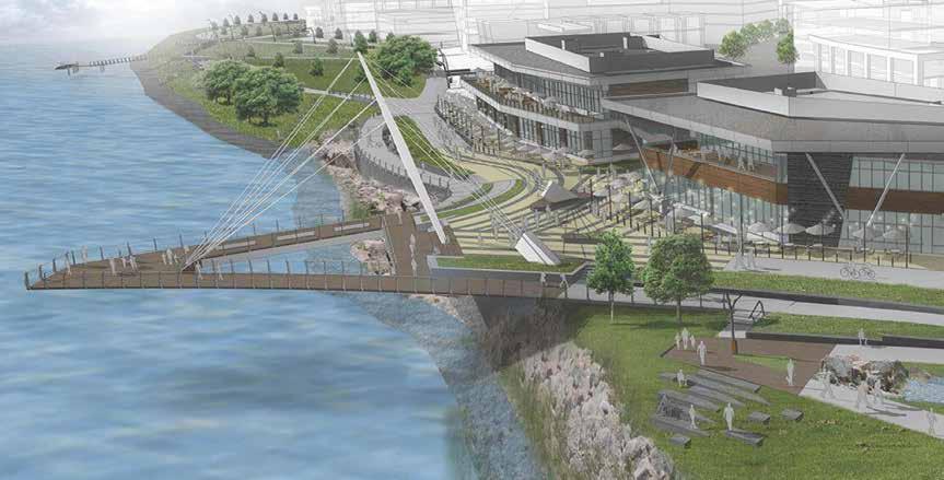
Grand Street Pier rendering.
Currently under construction in Vancouver, Washington, Waterfront Park is part of a 32-acre mixed-use urban redevelopment project on a site that is being reclaimed, having previously been used as a paper mill. Developed by the City of Vancouver, the 7.3-acre Waterfront Park features open lawns, picnic areas, viewpoints, and shoreline paths along nearly 2,500 feet of Columbia River waterfront. When completed in the Spring of 2018, the Grant Street Pier will become the focal point of the new park. Th e Grant Street Pier is a concrete, cable-stayed structure projecting almost 110 feet over the Columbia River. Th e 2½-inch diameter steel cables are anchored at the end of the pier and at two concrete backstays. Th ey are supported at the center by a 75-foot-tall steel pipe mast. Th e pier deck is three-foot-thick post-tensioned concrete that tapers to only six inches thick at the outside edges. A concrete abutment supports the pier deck, the mast, and one of the two backstays. Th e second mast backstay is anchored into an independent mat footing supported on 11 micropiles. Sliding of the backstay anchor footing is restrained by three grade-beams attached to the abutment slab. Th e concrete abutment wall is two feet thick at the base and tapers up to six-and-a-half feet thick at the top. Th e wall taper was a desired aesthetic for the pier base just above the waterline. Seven 18-inch-thick counterfort walls, orthogonal to the abutment wall, anchor the pier slab to the mat foundation. Th e mat foundation is a six-foot-thick concrete slab supported by twenty-seven fi ve-foot-diameter drilled shafts. Serious problems developed during the construction of the drilled piers, resulting in extensive and expensive repairs.
Foundation Design
Th e overall abutment foundation layout was highly constrained by the site – the Columbia River on the south edge, a property line boundary to the north, and a large sewer pipe that runs through the center of the footprint that could not be realigned for this project. One requirement of the permit was that the foundation could not be located waterward of the biological ordinary-high-water mark (OHWM). Th us, the alignment of the OHWM dictated that the foundation orientation be non-perpendicular to the primary axis of the pier span over the water. Th is resulted in a skewed axis of the mat slab foundation and drilled shafts relative to the main axis of the abutment walls and pier, resulting in a substantial torsion on the foundation mat slab in addition to the expected fl exure and shear. Th e underlying soil consisted of 25 feet of loose fi ll over ten feet of sand and then gravel and cobbles to depth. Th e loose fi ll contained sand, organics, some silt, wood debris, and large pieces of concrete debris. Th e concrete debris was not discovered by the geotechnical borings. Th e fi ll material and sand are subject to liquefaction during a seismic event. Because of the topography of the underlying gravels and the riverbank, these materials are also subject to lateral spread toward the river, with an estimated lateral spread of up to 15 feet. Because the excavation for the foundation was below the river level, a sheet pile coff erdam was needed to facilitate the pier foundation construction. Th e portion of the coff erdam that encroached on the OHWM was required to be removed; however, the landside portion of the coff erdam could remain. It was decided to utilize this portion of the coff erdam to resist demands due to liquefaction. As such, 36 tieback anchors were needed along the back face of the sheet pile coff erdam to resisting the primary demand of lateral spread. Th e tops of the sheet piles were cut off fi ve feet below grade; since this was below the top of the pier slab, the abutment and drilled shafts were required to resist the portion of liquefaction demand not supported by the sheet pile wall. Th e bottom of the mat slab foundation is 14 feet below the OHWM and approximately 15 feet above the gravel and cobble layer. Th e result is that 15 feet of soil below the mat foundation has the potential to liquefy due to a seismic event. Th is resulted in the drilled piers being designed as cantilever elements when subject to seismic demands. Th e seismic overturning, when combined with the overturning of the cantilever pier, created axial loads of almost 2,000-kips compression and bending moments of 45,000 kip-ft in the forward most drilled shafts, and tension loads of 610-kips and bending moments of 42,000 kip-ft in the rearmost drilled shafts based on allowable load combinations. Th ese demands and the geotechnical conditions required drilled
shafts with up to 70 feet of embedment into the gravel, resulting in a total shaft length of 90 feet.
Construction
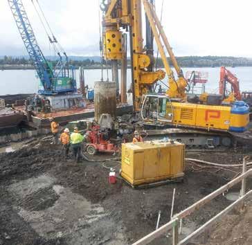
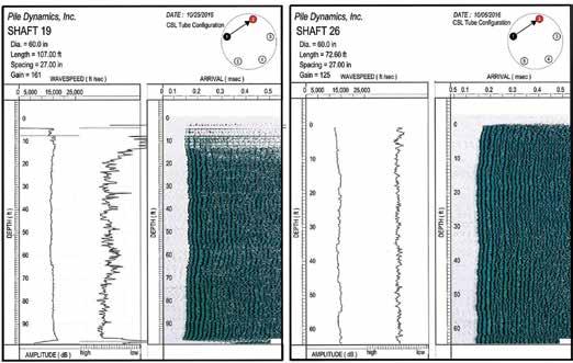
The shafts were installed with oscillating sectional casing using a Bauer BG40 track-mounted drill rig. Material inside of the casing was excavated using a digging bucket, a cleanout bucket, a flight auger, and a rock auger depending on the material encountered. During the drilling process, a water head was maintained above the river elevation to prevent heaving. After the shafts were drilled and cleaned, the reinforcing cage was lowered into the shaft and concrete was placed using a tremie pipe. As the concrete level rose, the casing was retracted. The drilling occurred from a bench CSL Data: compromised drilled shaft on the left, sound drilled shaft on the right. elevation 10 feet above the top of the drilled pier. The contractor excavated for the cofferdam tremie seal these shafts happened to be the deepest and most heavily loaded and mat foundation after the drilled shafts were installed. This shafts on the pier abutment. difference in elevation was taken up by a weak concrete mixture that could easily be chipped away from the shaft dowels once the excavation for the mat slab was complete. During the retraction Testing of the casing of the two final shafts, some construction problems Each drilled shaft was evaluated using Crosshole Sonic Logging were encountered. The issues for both shafts were similar – as the (CSL) in accordance with ASTM D 6760. The tests are performed last segments of casing were withdrawn, the top of concrete fell by a transmitter probe that converts electrical pulses into ultrasonic about 2.5 feet below the bottom of the top collar leaving a portion waves. A receiver probe measures the ultrasonic waves. The probes of shaft uncased. The soil around the top collar settled as the con- are sent down parallel steel pipes that are cast in the shafts. There tractor continued to place concrete in the shaft. One shaft took 14 are a total of five pipes for CSL per drilled shaft. The CSL data more yards of concrete than the estimated shaft volume, while the indicated possible flaws in the top 8 feet of one shaft and the top other shaft took on 20 more yards than expected. Coincidentally, 3 feet in the other shaft. Although core samples taken from the center of shafts did not reveal flaws, the concern was about the cover around the reinforcing cage. Thus, a request was made for the top four feet of the shafts to be exposed for visual observation, where moderate-sized chunks of concrete from the loose fill were found embedded in the sides of the shaft. The contractor was then required to probe the six inches of concrete cover using a rotor hammer drill with the longest available drill bits. On more than one occasion, while drilling vertically into the cover, the concrete offered little to no resistance. Also, the air from the drill would periodically force water out of holes on the opposite sides of the shaft. This process revealed weak, porous concrete cover of the shafts.
Installation of drilled shaft.
Drilled Shaft Repair
The design team had little confidence that these shafts had adequate corrosion protection for the reinforcing steel, and were thus considered unreliable for long-term performance. Consequently, the capacity of these drilled shafts had to be replaced. The solution preferred by the contractor was to drive H-piles locally around the compromised shafts to replace the missing capacity. However, even with as many H-piles as could physically fit within the mat foundation geometry, this solution was not practical because of the stiffness incompatibility between the new H-piles and the adjacent drilled shafts. Variations of
Structural components of foundation abutment.
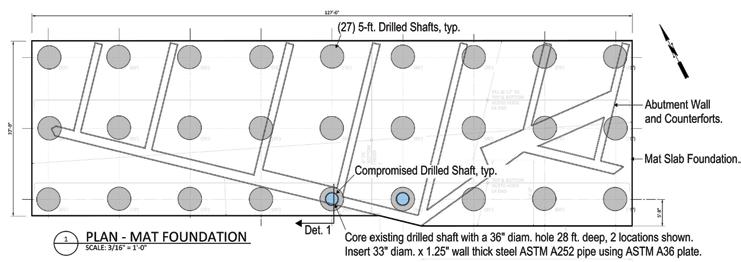
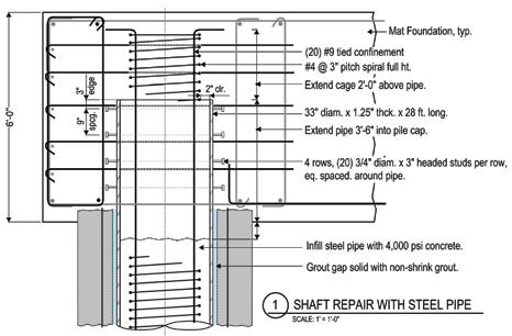
the repair option to excavate, remove the concrete cover, and re-cast concrete were attempted, but ultimately were abandoned because of worker safety and constructability concerns. One option dismissed early on in the process was revisited – to core the center of each drilled shaft and insert a concrete-filled steel pipe through the region of the compromised shaft. This was made possible only by an ability to core a large diameter hole in the center of the existing shaft using a rock auger without interfering with the existing reinforcing cage. Ultimately, a 36-inch diameter auger was used to core the center of each shaft a minimum of 12 feet below the location where it was believed, based on drilling and CSL data, each existing shaft was compromised. This allowed a 33-inch diameter x 1.25-inch thick steel pipe to be placed inside the core and extend 42 inches into the mat slab. Overall, a 28-foot length of pipe was needed for each shaft. This allowed the concrete-filled pipe to Altered structural conditions at the top of the concrete-filled steel pipe repair. act over the compromised portion of the drilled shaft and ultimately transfer loads back to the existing shaft below. The analytical model used in the original evaluation was revised Lessons Learned using the structural properties of the repaired shaft, with particular During shaft excavation and repair, the engineers and the contractor attention given to the boundary conditions at the top of the pipe. suspected that the excavations for the drilled shafts encountered a Although there was an approximate 7% shift of axial demand local subsurface area fill that contained sizeable concrete rubble and to the adjacent uncompromised shafts, the concrete-filled pipe large void areas. When these voids were exposed by the removal of recovered most of the stiffness of the original shaft to make the the temporary casing, the concrete flowed into the voids. compromised shafts effective. The analysis also showed that it was The contractor’s sequence called for the drilled shafts to be conessential to develop as much bending capacity at the top of the pipe structed before excavation for the cofferdam tremie seal or mat slab. as possible to minimize the redistribution effect. Consequently, When the tremie seal and mat slab excavation occurred, the contractor this bending resistance was achieved considering three compo- pulled out broken concrete slabs in the vicinity of the problem shafts, nents – the addition of a spirally tied reinforcing cage to help validating the suspicions. engage the concrete core of the pipe, the embedded portion of the Drilled shaft repairs are expensive and time-consuming. The repair pipe extension above the bottom layer of slab reinforcement, and for the drilled shafts cost approximately 120% of the original drilled headed studs added around the pipe perimeter to directly engage shaft installation. When projects are constrained by short in-water the pipe wall in bending. Additional detailing was needed in the work periods, schedule delays can be particularly troublesome. For mat slab to support the high local demands from the pipe flexure waterfront structures with deep foundations in areas of historic waterat the top. This bending moment at the bottom of the pipe was front development, the risk associated with unknown and variable redistributed to the shaft by the socketed 12-foot embed length, subsurface conditions is high. This risk can be partially mitigated by where the shear demand to engage bending was limited to the performing more exploratory geotechnical borings, or limited-depth shear capacity of the shaft reinforcement. This determined the potholing, than would be typical for an upland or undeveloped site. effective embedment of the pipe in the competent portion of the The pre-design geotechnical borings performed at the site indicated original drilled shaft below. fill and woody debris but did not indicate concrete. It is possible that
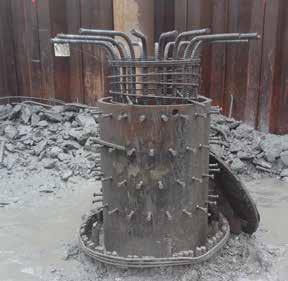
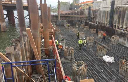
Foundation under construction: a repaired shaft (left) and bottom layer of reinforcement in mat slab (right).
a more comprehensive geotechnical exploration program would have alerted the designers to the concrete debris field, and provisions could have been established within the design documents (such as requiring permanent casing within the fill zone at the concrete debris field) to lessen the risk. However, designing to account for all unknowns can be expensive as well. The balance of risk associated with deep foundations is often the trickiest part of waterfront project development, and owners may not be fully aware of the risks. The construction of the Grant Street Pier foundation provides a case study in the potential risk associated with drilled-shaft deep foundations.▪ Dominic A. Webber, P.E., S.E,. is a Structural Engineer with BergerABAM, Inc. He is involved with building and marine structure design as well as design/build projects with geotechnical construction firms. Dominic can be reached at dominic.webber@ abam.com. Howard A. “Hod” Wells, P.E., LEED AP, ENV SP, is a Senior Project Manager with BergerABAM, Inc. He is involved with transportation and marine structure design in the Pacific Northwest. Howard can be reached at howard.wells@abam.com.
ADVERTISEMENT–For Advertiser Information, visit www.STRUCTUREmag.org
RFEM 5

Structural Analysis & Design Software & Design Software

Hotel Intercontinental Davos, Switzerland © www.ssp-muc.com
DOWNLOAD FREE TRIAL
www.dlubal.com
Powerful, Intuitive & Easy
USA & Canada Standards Nonlinear FEA
Dlubal Software, Inc.
Philadelphia, PA (267) 702-2815 info-us@dlubal.com www.dlubal.com
BIM Integration
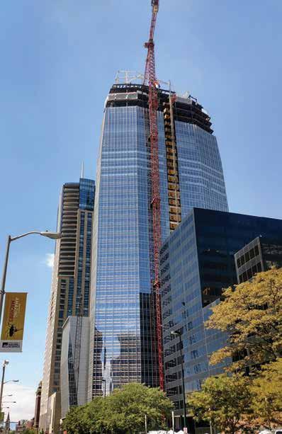
North face of iconic 1144 Fifteenth at topping-out ceremony in July 2017.
Unconventional Foundation
Stabilizes Denver Skyscraper
By Benny I. Lujan, P.E.
In the heart of Denver’s Theatre District, the city’s fourth tallest building is steadily rising from the ground. The 42-story, 603-foot-high LEED Pre-Certified Gold building, called 1144 Fifteenth, is the first Class A office tower built in the downtown area in more than 30 years. The soaring glass structure is an emblem to the city’s future. The building will rise above the rest – literally and figuratively. However, securing its strong foundation presented a long list of challenges. First and foremost was the ground itself. There is a reason the buildings of Denver’s skyline are primarily low compared to the skylines of other U.S. cities. As compared to New York, that is underlain by strong bedrock like schist, the comparatively soft rock (intermediate geomaterial) prevalent throughout Colorado’s Front Range cannot withstand the loads induced by very tall buildings, particularly with a dense office use. Moreover, soil and bedrock conditions can vary significantly within any individual foundation area. Secondly, land is scarce in Denver and the 1144 Fifteenth site – in a prime location – is a tight one, bound by downtown streets on three sides with the equally iconic Four Seasons Hotel on the fourth. The architectural team needed as wide a base as possible, so the foundation was designed “property line to property line.” Needless to say, when Martin/Martin Consulting Engineers tapped CTL|Thompson’s geotechnical engineers Marc Cleveland, David Glater, and Benny I. Lujan, it was with a pretty sizable task: design a building foundation for a very visible and very heavily-loaded skyscraper in a tight building envelope and sitting on the area’s sedimentary bedrock. The team had to dig deep, but ultimately they came up with a way to get the difficult job done – create a foundation design using a shoring system that allowed lateral loads from the drilled pier/tie-beam core foundation to be transferred directly to undisturbed bedrock.
Problem Solving
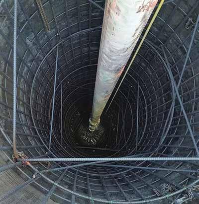
During soil testing, the CTL team identified that bedrock was at the elevation of the building’s lower level. The shallow bedrock could have presented an additional challenge, but CTL, along with Martin/Martin engineers, used it to their advantage. Instead of excavating the bedrock to support a conventional drilled pier and thick monolithic reinforced concrete mat core, the team designed a system using a tie-beam connecting and supported by drilled piers. This system would rely on undisturbed bedrock around the perimeter lateral face of the tie-beam system to transmit a portion of the lateral load to the bedrock. The process would require the piers to be poured 7 feet below basement grade and the installation of vertical concrete and steel beam soldier
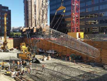
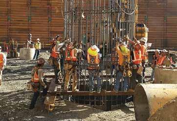
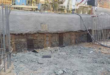
Reinforcing steel cages form the drilled piers used in the foundation for 1144 Fifteenth Street. Due to the length of the piers, the reinforcing steel was built in two sections that were spliced together. Here the second section is hoisted into place. Team members prepare to form the tie beam system that will support the foundation of 1144 Fifteenth Street. The bedrock is covered with an earth retention system and shotcrete; drilled piers line the top and right.
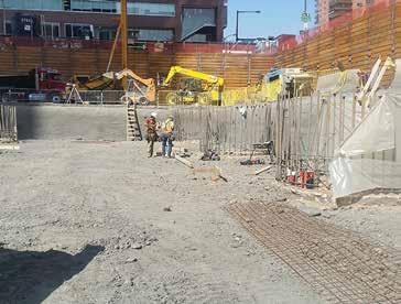
piles around the perimeter before excavating. The excavation at the core perimeter would expose the top of the foundation piers, soldier piles, and bedrock. After the bedrock surface was cleaned, the reinforcing mesh would be placed and attached to the soldier piles; then shotcrete would be applied pneumatically to protect the bedrock and preserve its strength.
Foundation Design
Before the non-conventional process could be attempted, the foundation needed to be designed. Martin/Martin and CTL created a tie-beam and drilled pier system with a footprint of 120 feet by 47 feet. The system included eight drilled piers, each ten feet in diameter and boring more than 100 feet into the bedrock, which supported seven-foot deep, seven-foot-wide tie-beams. Two longer beams would run along the longitudinal axis of the building and be pulled together by four shorter, perpendicular beams. It was designed to “kiss” the undisturbed bedrock at 29 feet below street grade and seven feet below the lower-level parking garage floor. As a result, lateral loads on the drilled piers that support the core foundation were reduced by using the bedrock’s passive resistance, in conjunction with lateral resistance provided by the drilled piers. The tie-beams were designed using one-sided forms and the hollow areas filled with a non-shrink, flowable fill mix, instead of soil or concrete. This design approach resulted in a value-added, more economical solution compared to the typical monolithic reinforced concrete core foundation.
The Execution
With the foundation designed, the engineering team began to outline a plan to carefully excavate the core foundation footprint to the top of the core drilled piers, keeping the bedrock intact and limiting any impact on the neighboring building. First, the perimeter of the core excavation was drilled and soldier piles installed along the outside edge of the planned face of the core excavation. A shotcrete-faced earth retention system was recommended for the perimeter to achieve the highest possible passive resistance. Because the bedrock is an overly consolidated sedimentary claystone which can become weathered, excavation for the site needed to be both careful and quick. When exposed to the elements for too long, the bedrock dries and disintegrates, reducing the strength that the design team was relying on for lateral support. To counter this issue, the contractor excavated in two phases and operated at about 1.5
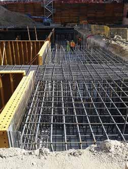
The tie beam system used in the foundation of 1144 Fifteenth Street. The architect’s rendering of the skyline-changing 1144 Fifteenth Street, the first Class A office tower built in downtown Denver in 30 years.
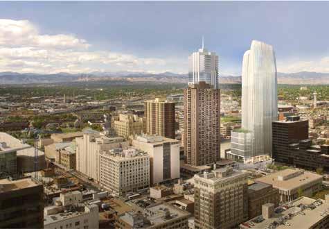
times a traditional pace. In the first phase, the contractor excavated three feet, installed reinforcing mesh tied to the soldier pile system, used compressed air to clean the exposed bedrock surface, and then applied shotcrete to protect it. After completion of the first 3-foot layer, the contractor extended the excavation to the design depth of 7 feet and the top of the ten-foot diameter piers, and repeated the process. A special concrete mixture was designed to minimize temperatures during the initial curing of the concrete. About the process, geotechnical engineer Benny I. Lujan of CTL|Thompson said, “Massive amounts of concrete generate significant heat during curing, which can be detrimental to the quality and strength of the concrete. Each pier had 300 yards of concrete, and we had eight piers. That is 30 truckloads of concrete for each pier. I have never seen anything like it.” Due to the volume of concrete needed for the piers and tie-beam system, a concrete mix design was created by the concrete supplier Martin Marietta, with assistance from fellow engineers at Martin/ Martin and CTL|Thompson. The mix included as much as 40 percent fly ash to create a lower heat of hydration and slow down the curing process. During placement, concrete temperatures were carefully monitored to keep within a tolerable range. Since the strength gain was slowed, the allowable minimum strength at 28 days was relaxed to a 56-day strength requirement.
Playing Nice with the Neighbors
Another solution was needed to negotiate the earth retention system for the site’s neighbor, the Four Seasons Hotel. The southern wall of the hotel had an older system of grouted tie-back anchors and soldier piles, with lagging and drilled piers remaining in place. The team created a tension system via counterforts to excavate the old system while avoiding the existing drilled piers supporting the structure. The process involved moving piers inward and doubling them up, then placing the newly designed piers. The team also had to find a creative way to design the tie-beam system along this southern edge, as the caissons could not be placed over existing piles. The design team moved planned columns from the south to the north side and designed a transfer beam system to support the southern edge to overcome the issue. Throughout foundation construction, surveyors monitored deflection, while lateral movement was monitored carefully and extensively by the construction team to ensure work on 1144 Fifteenth would not result in tilting, cracking, or vibration to the hotel’s below-grade parking garage and its foundation.
Bringing Downtown Denver to New Heights
The unique, sky-line changing office building “topped out” in July 2017, right on schedule, and is expected to be complete in Q1, 2018. When complete, visitors and users will never notice the ground beneath them, but the foundation is just as unique as the building, with extensive, nonconventional engineering solutions that overcame potentially project-derailing issues. The result is a foundation that will not only withstand the heavy loads of the building but will also serve as an example to the industry. “Approaching this extensive project required research, speculation, experience, calculation, patience, and creativity,” said Lujan. “We were faced with an enormous challenge, and our goal was to determine the most effective engineering solutions to complete the project without compromising quality. It was not easy, but together with our friends at Hines and Martin/Martin, we developed an unconventional, innovative, and costeffective technique to building the core foundation for 1144 Fifteenth.”▪
Benny I. Lujan, P.E., is a Geotechnical Engineer with CTL|Thompson, a full-service geotechnical, structural, environmental and materials engineering firm.
Project Team
Owner: Hines Interests Limited Partnership Engineer of Record: Martin/Martin Consulting Engineers Architect of Record: Kendall/Heaton Associates Contractor: Hensel Phelps Construction Company
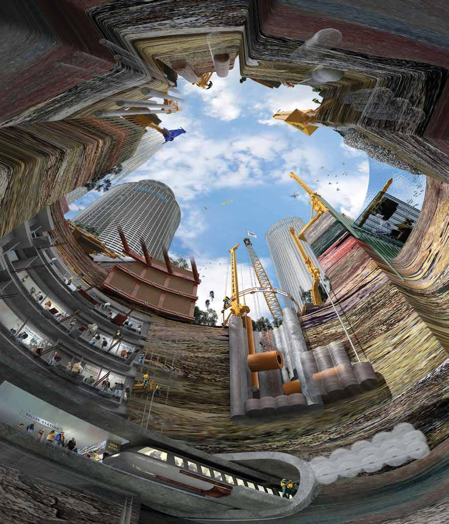


Courtesy of HOK
Category 1: New Buildings under $20 Million OUTSTANDING PROJECT
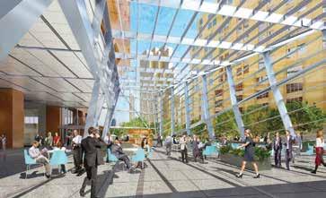
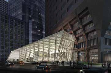
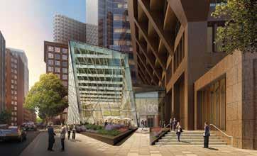
The Exchange at 100 Federal Street
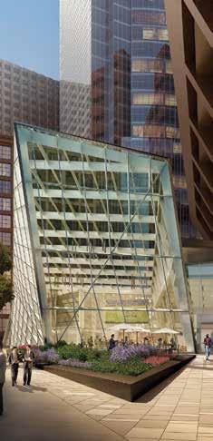
Boston, MA | McNamara • Salvia Structural Engineers e Exchange at 100 Federal Street is a pavilion that was envisioned as a dynamic, faceted form in structural steel with a glass façade. A variety of steel shapes were considered, but none could be costeff ectively sized for the 75-foot main spans and still achieve the vision for the structure. e solution was solid plate members with exposed bolted connections, limited by steel availability to 4 inches thick. e original architectural desire for narrow steel shapes and a dynamic form was realized. e benefi ts of collaborative design loops, open communications, and creative thinking provided a fi nal form that shows dynamic character from every viewing angle. The National Council of Structural Engineers Associations (NCSEA) is pleased to announce the winners of the 2017 Excellence in Structural Engineering Awards. e awards were announced on the evening of October 13 at NCSEA’s 25th Annual Structural Engineering Summit in Washington, D.C. e awards have been given annually since 1998 and, each year, highlight work from the best and brightest in our profession. Awards were given in seven categories, with one project in each category named the Outstanding Project. e categories for 2017 were: • New Buildings under $20 Million • New Buildings $20 Million to $100 Million • New Buildings over $100 Million • New Bridges and Transportation Structures • Forensic/Renovation/Retrofi t/Rehabilitation Structures up to $20 Million • Forensic/Renovation/Retrofi t/Rehabilitation Structures over $20 Million • Other Structures e 2017 Awards Committee was chaired by Carrie Johnson (Wallace Engineering Structural Consultants, Inc., Tulsa OK). Ms. Johnson noted: “We had a record number of entries this year and the quality of projects was outstanding. Our judges for 2017 were from the Structural Engineers Association of Illinois. ey had an enormous task of trying to determine winners from an excellent group of submittals. ey did a great job of thoroughly analyzing each entry and thoughtfully discussing which ones should receive the award.” More in-depth articles on several of the 2017 winners will appear in the Spotlight section of the magazine over the course of the 2018 editorial year.
Category 3: New Buildings over $100 Million OUTSTANDING PROJECT
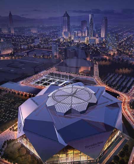
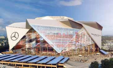
Mercedes-Benz Stadium
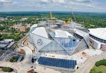
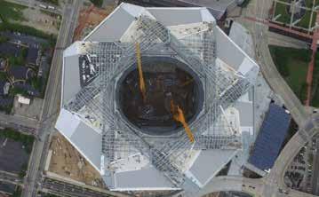
Atlanta, GA | BuroHappold Engineering The multi-purpose Mercedes-Benz Stadium, home for the NFL’s Atlanta Falcons and the new Atlanta United, a Major League Soccer team, will cover almost 2 million square feet. It will accommodate seating for approximately 80,000 fans. BuroHappold developed a unique retractable roof concept that opens in 19 minutes or less by moving eight “petals” that create an exciting pinwheel appearance when in motion. The petals are clad in over 120,000 square feet of double-skin ETFE cushions, a transparent, lightweight material that exerts minimal weight on the petals and their long, cantilevering spans. When the petals slide open, the oval-shaped roof opening spans the length of the field past each end zone.
Courtesy of Mercedes-Benz Stadium
U.S. Air Force Academy Center for Character and Leadership Development
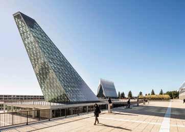
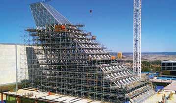
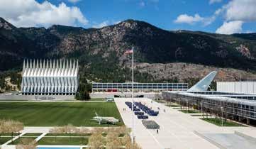
Colorado Springs, CO | Skidmore, Owings & Merrill, LLP The Center for Character & Leadership Development’s (CCLD) dramatic cantilevering, 105-foot Skylight structure consists of a triangulated system of Architecturally Exposed Structural Steel plates of varying depth and calibrated to resist lateral forces due to wind loadings. This glass-enclosed structure aligns precisely with the North Star, Polaris, signifying and reinforcing the Academy’s mission to integrate character and leadership development into all aspects of the Cadet experience. The Skylight is designed as a series of “stacked trusses” to minimize the number of field connections as one measure to ensure that the building could be constructed easily.
Courtesy of Mercedes-Benz Stadium
Courtesy of HOK
Category 4: New Bridges or Transportation Structures OUTSTANDING PROJECT
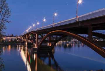
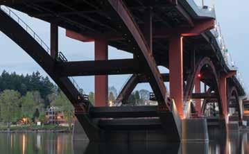
Sellwood Bridge Replacement
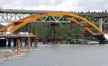
Portland, OR | T.Y.Lin International The Sellwood Bridge is located on a vital route in Portland, Oregon. A unique design solution was developed where the entire 1,100-foot-long four-span continuous steel deck truss of the old bridge was slid over to temporary piers on a detour alignment to accommodate construction of the new bridge. The new 1,976.5-foot-long bridge, 1,275 feet of which is steel deck arch, carries two 12-foot wide vehicular lanes, two 6.5-foot-wide bike lanes, and two 12-foot-wide sidewalks, and will accommodate future streetcar service. The new structure has an advanced ductility-based seismic design for both operating and strength level earthquakes.
Category 5: Forensic/Renovation/Retrofit/Rehabilitation Structures under $20 Million OUTSTANDING PROJECT
The Desmond Building
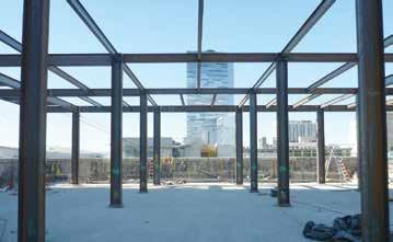
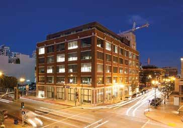
Los Angeles, CA | Skidmore, Owings & Merrill LLP Located in downtown Los Angeles’ South Park commercial district, The Desmond Building has recently been infused with new life through a full renovation and seismic retrofit. The 1916 era building stood empty for many years and, with the city’s focus on seismic safety of non-ductile concrete buildings, had been identified as “at-risk.” Renovated for highend creative office use, the building maintains its original industrial aesthetic and historic character. A successful implementation of a rigorous, code prescriptive retrofit solution enabled the addition of a lightweight, income-generating sixth story. The Desmond exemplifies how other historic properties can be safely renovated while including new additions.

Category 7: Other Structures OUTSTANDING PROJECT
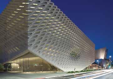
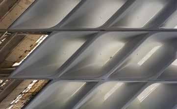
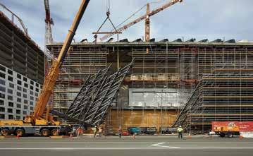
Broad Museum Veil
Los Angeles, CA | John A Martin & Associates, Inc. An innovative design that features a “veil and vault” concept defined the project at the Broad Museum in Los Angeles. The veil is a structural exoskeleton, a honeycomb-like structure that drapes over the building’s interior vault. This porous yet absorptive screen is made of 2,500 fiberglass reinforced concrete (FRC) panels and 650 tons of steel. It forms a 3-D series of open cellular components that channels light into public spaces and galleries and connects the museum to the Downtown Streetscape. An elegant steel frame realized through the use of rigorous analysis, testing, and creative support strategies allow this stand-alone piece an expression that fulfills dual functional and aesthetic roles. Category 6: Forensic/Renovation/Retrofit/Rehabilitation Structures over $20 Million OUTSTANDING PROJECT
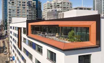
Bay Area Metro Center
San Francisco, CA | Holmes Structures Serving as the regional headquarters for various government transportation entities, The Bay Area Metro Center was built in 1942 as a WWII tank assembly plant. With a limited budget, this heavy reinforced concrete structure required a seismic retrofit for its change to commercial offices. Holmes Structures “lightened” the building by removing mass from the interior floor plates and added selective perimeter strengthening without altering the foundation. Performance-based engineering was used to design a retrofit that leveraged the capacity of the existing structure. The solution spread lateral resisting members around the perimeter, distributing the loads over a larger area and eliminating the need for new, deeper foundations.
Courtesy of Hunter Kerhart
AWARD WINNER – CATEGORY 1
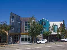
1908 Shattuck
Berkeley, CA | Tipping Structural Engineers This downtown Berkeley project includes a restaurant-brewery at street level and an office space on the second and third floors. Given the area’s high seismicity, engineers elected to design an essentially earthquakeproof building employing seismic isolation. Because retaining walls already existed on three sides of the lot, alternative isolation configurations were considered. Exposed bearings, spliced into the ground-floor columns ten feet above grade, are visible to the public. Practice would dictate employing isolation bearings with a 36-inch allowable horizontal movement at this site. To maximize real estate, TSE customized isolators for a 24-inch allowable movement.
AWARD WINNER – CATEGORY 1
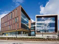
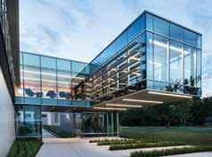
The Collegiate Center at Edison
Tulsa, OK | Wallace Engineering – Structural Consultants, Inc. The Collegiate Center at Edison presented a unique challenge: design a facility incorporating diverse functions such as safe rooms, lecture halls, and an academic hall while creating a building that was iconic as well. The student lounge is the most striking feature of the building, appearing to hover fourteen feet above an outdoor plaza located along a busy arterial street. The lecture halls serve as ICC-500, FEMA-361 safe rooms. Designed to resist the wind pressures and debris impact from an EF-5 tornado, or approximately 250 mph wind speeds, they provide shelter for up to 300 people during a tornadic event.
Courtesy of Forestry Innovation Investment
AWARD WINNER – CATEGORY 2
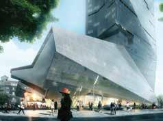
TallWood House at Brock Commons
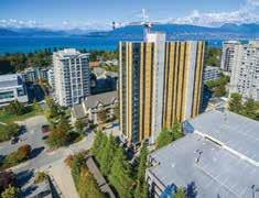
Vancouver, BC | Fast + Epp The TallWood House at Brock Commons is an 18-story, mass timber hybrid, student residence at the University of British Columbia (UBC) in Vancouver, Canada. It has been recognized as the tallest mass timber hybrid building in the world, reaching 174 feet (53m). The building is comprised of 17 stories of unique structure: five-ply crosslaminated timber (CLT) floor panels, point supported by glue-laminated timber columns, all resting on a concrete transfer slab at level two. Two full height concrete cores provide the lateral stability. Eighteen fullscale load tests were performed to verify the custom CLT panel’s capacity.
AWARD WINNER – CATEGORY 2
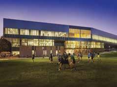
California Polytechnic University, Student Recreation Center
Pomona, CA | LPA, Inc. Located on the campus of California State Polytechnic University in Pomona, California, the Student Recreation Center has become a focal point of student activity on the primarily commuter campus since the facility opened in 2014. The dramatic three-story structure seems to defy gravity even more than the rock climbers inside, featuring several substantial cantilevered floor areas, the largest of which extends nearly 60 feet to support an indoor running track. The 165,000-square-foot facility addresses multiple structural challenges by marrying the performance of structural steel framing to this unique building form. STRUCTURE magazine 34 December 2017
AWARD WINNER – CATEGORY 2
University of Massachusetts Design Building
Amherst, MA | Simpson Gumpertz & Heger Inc. The University of Massachusetts (UMass) wanted to bring their design programs – Architecture, Landscape Architecture and Regional Planning, and Building and Construction Technology – together in one creatively designed building exemplifying sustainable construction practices. While a steel- or concrete-framed structure would be conventional for this building’s size and use, the new Design Building features a timber-framed superstructure with an innovative composite floor system. The exposed wood structure emphasizes the potential of engineered wood elements while complementing and influencing the aesthetics inside and out.
Courtesy of Morphosis
AWARD WINNER – CATEGORY 3
Hanking Tower (Rolansburg)
Shenzhen, China | WSP The Hanking Center in Shenzhen is a 1,150-foot-tall (350m) innovative architectural form, including a detached core and folded angled exterior. The challenges of the eccentric core design are overcome by a unique structural steel solution – a ‘mega-braced’ tube structure, using composite columns linked by steel diagonal bracing organized over multi-story modules around and through the tower. The result is a closed tube structure, efficiently engaging the entire tower depth and integrated within the architectural design. Minimal floor links, as envisioned between the tower and offset core, are maintained with light bracing integrated only at select levels.
AWARD WINNER – CATEGORY 3
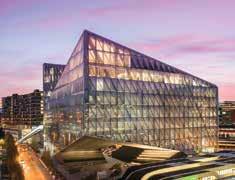
JTI Headquarters
Geneva, Switzerland | Skidmore, Owings & Merrill LLP Framed in structural steel, the 10-story JTI Headquarters in Geneva, Switzerland, was achieved by using creative structural engineering design and an innovative application of both design and construction techniques. The building’s striking form was primarily dictated by the triangular shape of the site, and 157-foot (48m) and 197-foot (60m) cantilevers created by lifting the northeast corner to allow for public space and scenic views. Combined moment frames and nested Pratt trusses at the building faces support both gravity and lateral loads. Potential excessive deflections were controlled during construction through a combination of camber, jacking, and tie-downs.
AWARD WINNER – CATEGORY 3
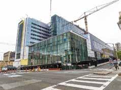
Sutter Health, California Pacific Medical Center, Viscous Wall Damper
San Francisco, CA | Degenkolb Engineers The CPMC hospital at the Van Ness and Geary Street campus is currently under construction. The hospital, to be completed in 2018, will consolidate the acute care services from two older CPMC campuses. The structure includes 274 patient beds, diagnostic and treatment centers, and subterranean parking. The structural system is a steel moment resisting frame with supplemental viscous wall dampers to reduce earthquake demands, the first use of this technology in the US. The project is being delivered using the Integrated Project Delivery method. The team was able to reduce waste in the design and construction of Sutter’s most significant project.
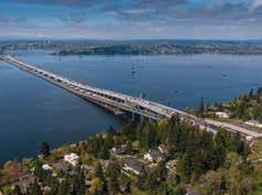
AWARD WINNER – CATEGORY 4
SR 520 Floating Bridge and Landings
Seattle, WA | KPFF Consulting Engineers The new SR 520 floating bridge replaces an old, structurally vulnerable floating bridge with a stronger, more resilient structure. The new bridge spans 7,708.5 feet across Lake Washington, forming the longest floating bridge in the world. Four structural types form the new bridge, each selected to address unique challenges and serve distinct purposes. On land, dual concrete box girders form the approaches. Steel transition spans connect the fixed structures to the floating bridge, allowing for differential movement between the structures. The floating bridge itself consists of floating concrete pontoons, concrete girder supported high-rises, and an innovative precast ribbed-slab low-rise structure.
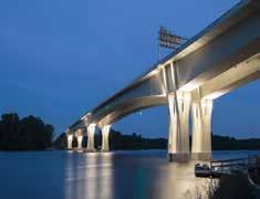
AWARD WINNER – CATEGORY 4 The New Dresbach Bridge
LaCrescent, WI | FIGG Bridge Engineers, Inc. The New Dresbach Bridge crosses the Mississippi River between LaCrescent, MN, and LaCrosse, WI. It demonstrates how innovative engineering can result in a beautiful, efficient, variable-depth, long span bridge thoughtfully built in sensitive environmental areas and during harsh winter conditions, all while achieving a new record span length (508 feet) for Minnesota. Its concrete segmental structures and custom formwork achieved context sensitive, signature shapes while being highly economical and delivered ahead-of-schedule. It met or exceeded all of Minnesota DOT’s project constraints, criteria, and goals: built rapidly, minimizing impacts on the public, achieving outstanding context-sensitive aesthetics, and being highly economical. STRUCTURE magazine 35 December 2017
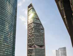
AWARD WINNER – CATEGORY 3
Torre Reforma
Mexico City, Mexico | Arup At 807 feet (246m), Torre Reforma will be the tallest skyscraper in Mexico. The 57-floor, 344,500-square-foot (40,000 m2) building includes office space, along with restaurants, shopping, and a 4-floor fitness club. Set along the bustling new commercial corridor of Paseo de la Reforma, the building’s unique triangular form responds to the setback limitations of the site and the preservation of a historic building on the site. A vital element of the project was to demonstrate how, through the integration of engineering and architecture, a high degree of sustainability and building performance could be achieved. Torre Reforma has been certified LEED Platinum.
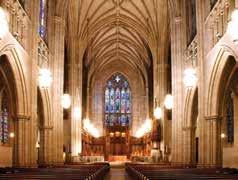
AWARD WINNER – CATEGORY 5
Duke University Chapel: Investigation and Restoration of Cracked Stone Arches
Durham, NC | Wiss, Janney, Elstner Associates, Inc. Duke University Chapel has a vaulted ceiling system that consists of rib arches constructed with individual stone voussoirs and a Guastavino ceiling system (clay tile and precast concrete) that spans between the arches. Unusual conditions that include cracks in mortar joints between voussoirs developed in the stone arches due to tensile stresses from long-term moisture expansion of the clay tile component of the Guastavino ceiling system. Restoration that included tuckpointing of mortar joints between voussoirs was completed August 2015, and the Chapel was subsequently reopened.
AWARD WINNER – CATEGORY 5 Freemark Abbey Winery
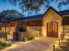
St. Helena, CA | ZFA Structural Engineers Originally constructed in 1886, Freemark Abbey Winery has undergone several modifi cations over the last 130 years. When purchased by Jackson Family Wines in 2006, their vision was to celebrate the history of the structure while bringing it into the modern era. Coined by SB Architects as the “rebirth” of the historic stone building, the $15M retrofi t and alteration project is providing Freemark Abbey, one of the original gravity fed stone wineries, with an iconic hospitality and events center located in the heart of Napa Valley. Structural solutions included utilizing existing stone walls, adding structural steel trusses and braced frames, and selectively placing new concrete foundations.
AWARD WINNER – CATEGORY 6
Empire Stores
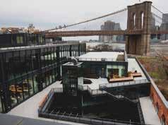
Brooklyn, NY | Silman Empire Stores is a landmarked structure on the DUMBO waterfront in Brooklyn Bridge Park. It is a series of seven interconnected structures constructed between 1870 and 1885 for use in the shipping industry, and, later, as a coff ee warehouse. Silman participated in its rehabilitation and renovation, which consisted of the restoration of the existing structure and the addition of two new stories. Also, the roof was transformed into a public park, and a public courtyard was created that cut a large slice through two of the buildings and includes a winding staircase that grants access to the roof. Overhead, at levels 3 and 4, two bridges fl y through the courtyard and connect the interior spaces on either side.

AWARD WINNER – CATEGORY 7
Black Rock Lighthouse Service
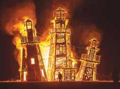
Black Rock City, NV | Holmes Structures e Black Rock Lighthouse Service was the largest independent art installation at Burning Man 2016, featuring four octagonal lighthouses connected with suspension bridges. e installation experienced 60+ mph wind and dust storms without sustaining structural damage and sheltered 70,000 attendees over the course of the festival. e engineering team provided extensive prototyping to ensure life-safety for structures with an unstable aesthetic. Prefabricated panels were prototyped and tested for mandatory rapid onsite assembly. Additionally, a fl exible anchorage system and meticulous clean-up procedures were implemented to respect Burning Man’s strict “leave no trace” policy.

Courtesy of christian phillips photography
AWARD WINNER – CATEGORY 7 Chicago Riverwalk
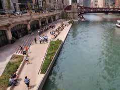
Chicago, IL | Alfred Benesch & Company e new 1.3-mile Chicago Riverwalk transformed discontinuous riverfront spaces along the Chicago River into 2,800 feet of continuous walkway that connects the Lakefront to Chicago’s West Loop. As Chicago’s “second shoreline,” the Riverwalk now serves as a premier, sustainable urban space consisting of six uniquely designed sections that integrate the original Riverwalk walls. e innovative project includes precast underbridges supported on drilled shafts that seamlessly connect each section along the walkway. e Riverwalk not only enhances the environment but enables residents, workers, and visitors to connect with the many recreational, cultural and economic amenities off ered by the Chicago River. STRUCTURE magazine 36 December 2017
AWARD WINNER – CATEGORY 6
UC Berkeley Bowles Hall Seismic Retrofit and Renewal
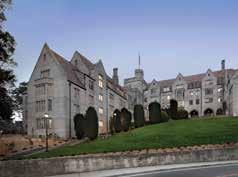
Berkley, CA | Maffei Structural Engineering Built in 1929 in the Collegiate Gothic style, Bowles Hall is the University of California’s fi rst residence hall. A western trace of the Hayward earthquake fault passes beneath two corners of the building. e 2016 renovation and retrofi t is the University’s fi rst public-private partnership for a seismic retrofi t project. e renovation revises the dormitory room layout to include bathrooms within units, adds wheelchair accessibility, replaces utilities, restores dining, and expands common spaces. Seismic retrofi t work includes concrete walls and a buttress at strategic locations to blend with the existing architecture while strengthening the structure for the site’s extreme earthquake hazard.
2017 Panel of Judges
e judging was held on Monday, July 24, 2017, at the NCSEA offi ces in Chicago, Illinois. e judges for this year’s Excellence in Structural Engineering Awards were: Carrie Johnson, P.E., SECB Wallace Engineering Structural Consultants, Inc. Ben Nelson, P.E., SECB Martin/Martin, Inc. Kevin Conroy, P.E., S.E. Simpson Gumpertz & Heger Salvatore DiBernardo, P.E., S.E. Ciorba Group Adam eiss, S.E., P.E. Magnusson Klemencic Jennifer Traut-Todaro, S.E. American Institute of Steel Construction
The smarter solution for building drift.

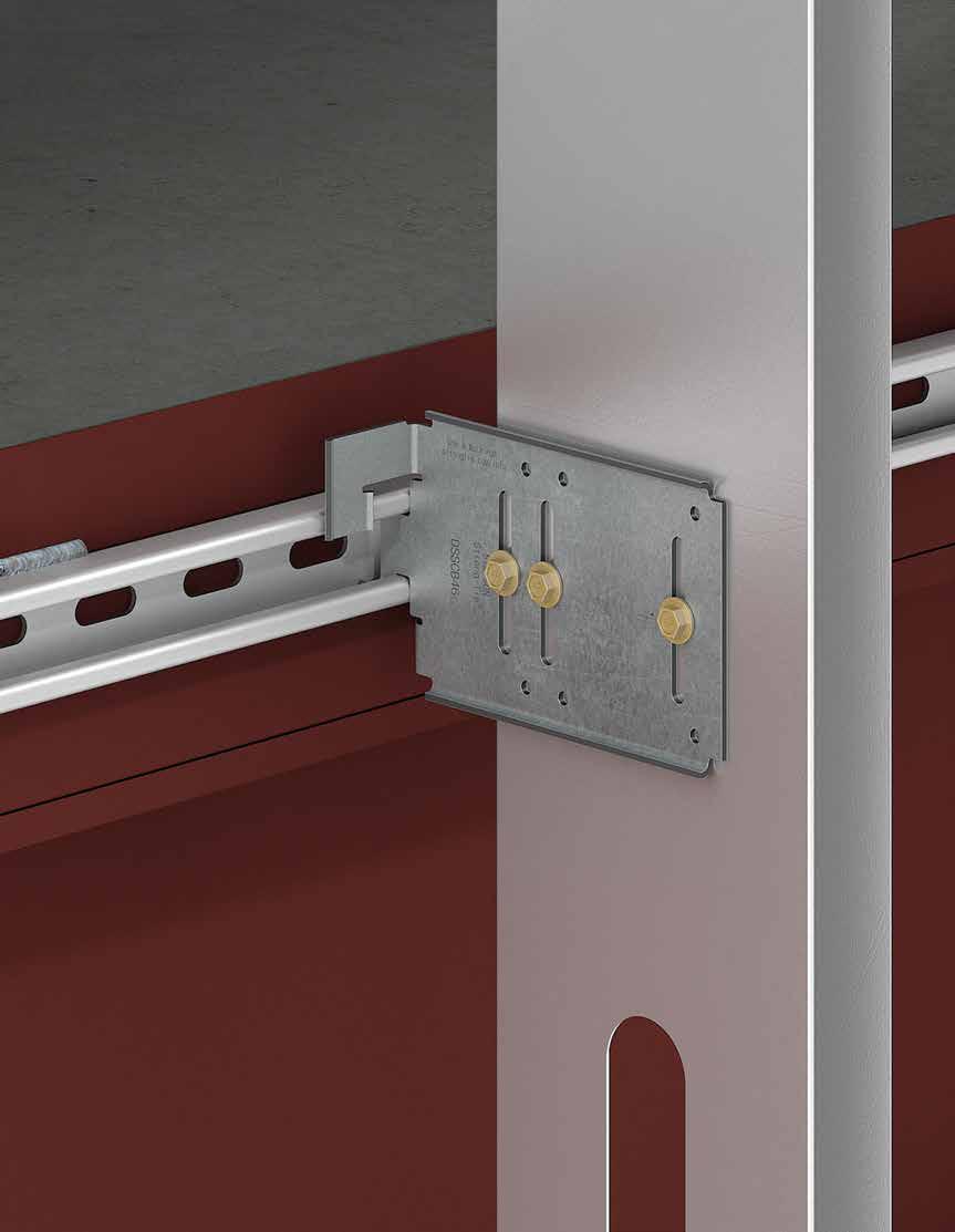
DSSCB The new DSSCB connector is the smart solution for building drift. Used to anchor cold-formed steel bypass framing to the edge of a floor slab, the DSSCB is designed and assembly tested to accommodate horizontal building drift. With prepunched slots and holes, our drift strut connector can be installed in slide-clip and fixed-clip applications. To learn more, visit go.strongtie.com/driftstrut or call (800) 999-5099.
An Oasis
for Children
in the River City
By Nathan C. Dumas, P.E., Jeff rey S. Davis, P.E. SECB, LEED AP BD+C, and Donna E. Adams, P.E. SECB
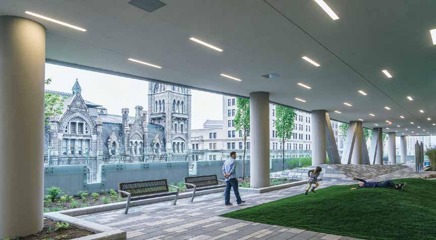
e Sky Lobby garden is perhaps one of the most inviting features to families seeking pediatric medical care at this facility. Courtesy of Michael Stavaridis.
This is the type of project that gives geotechnical, geostructural, and structural engineers goosebumps – in a good way. VCU Health’s vision for a new Children’s Hospital of Richmond at VCU Children’s Pavilion required designing in the fourth dimension, where the past, present, and future of the physical facilities critical to this ambitious undertaking were simultaneously considered. Goals were lofty. Not only would it become the largest and most advanced outpatient facility dedicated to children in the region, but the reimagined pavilion was also expected to serve as a gateway to Virginia Commonwealth University’s urban medical campus in downtown Richmond. And that was just for starters. On the surface, the program directive to the design team, led by HKS Architects, Inc., was clear and concise. With an all-in budget of $200 million, on a site adjacent and practically connected to the existing Children’s Pavilion, design and construct a 640,000-squarefoot, 15-story building rising 11 fl oors above grade and descending four stories below it. e design had to incorporate structural systems that would allow for seven fl oors of future vertical expansion and also extend the below-grade levels to the north, occupying the entire block. Last but not least, although the plan required demolition of a portion of the existing pavilion, it had to remain open and operational during construction. Together, these factors formed an irresistible challenge for two local engineering fi rms to surmount. As part of the HKS team, structural engineer Dunbar Milby Williams Pittman & Vaughan (DMWPV) and geotechnical/geostructural engineer Schnabel Engineering were charged with designing the support of excavation, the structural support and underpinning of the existing pavilion, and structural support of the new building.
Location, Location, Location
Previously a surface parking lot, the project site occupies less than an acre and is bounded by busy East Broad Street, and North 10th and 11th Streets. With the adjacent pediatric pavilion already in place, VCU saw the expansion as a means to enhance their brand and re-energize the neighborhood and campus gateway while consolidating services from various locations under one roof to better serve the community. e new Pavilion at 1000 E. Broad Street is on a GRTC Transit System bus route and features a 600-space attached parking garage.
Diving into a Deep Excavation
Extensive subsurface exploration – 23 test borings, a cone penetrometer test, three pressuremeter tests, and strength and consolidation testing on Shelby tube samples – confi rmed the site geology to be typical of downtown Richmond. e good news was that the Miocene clay and silt soils were heavily pre-consolidated and suitable for support of heavy building loads. e real challenge lay in the fact that the excavation for the new Pavilion extended 55 feet below street level, which is 35 feet below the foundations of the existing pediatric care facility. is prompted creative thinking and serious teamwork on the part of DMWPV and Schnabel to address two pivotal issues: excavation support and existing building support.
Excavation Support
A permanently tied-back soldier pile and lagging support of excavation (SOE) system was selected based on consideration of the subsurface conditions, and site and design constraints. e system can resist the lateral earth pressures instead of relying on the building framing and facilitates future expansion to the north. Schnabel performed the initial SOE design, which was subsequently optimized by design-builder Nicholson Construction. e system consisted of 143 drilled and set piles and 472 tiebacks and was designed to limit horizontal and vertical defl ection of the adjacent building to one inch.
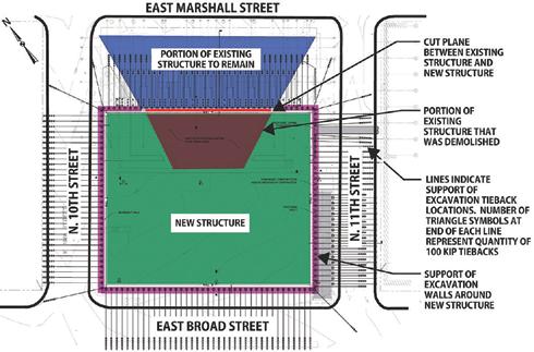
systems to compensate for unbalanced lateral earth pressure and to keep the building from moving toward the excavation. The structure to remain in place after demolition was modeled using Autodesk Revit and Bentley RAM Elements finite element analysis software. Multiple options to support the lateral loads on the structure and transfer approximately 2,300 kips of service level lateral load to the soils below were considered; internal buttresses and shear walls was the option of choice. The buttresses consist of seven 9-foot by 6.75-foot, full-height concrete columns spaced at 24 feet on-center along the cut plane, each with an integral 2-foot-thick concrete shear wall perpendicular to the line of excavation. The continuous underpinning grade beam at the cut plane connects the buttresses and is supported by the system of vertical micropiles detailed Site location and position of the new building relative to the existing pediatric care building. above. The groups of micropiles are centered between the SOE tiebacks. Existing Building Support To resist the lateral forces and prevent the building from moving towards the excavation, an A-frame system of post-tensioned battered The excavation below and adjacent to the pediatric care facility at piles coupled with vertical micropiles was constructed 30 feet away the demolition cut plane necessitated supporting the existing shallow from the building cut plane, in line with the vertical micropiles along foundations. Because the two structures were to remain independent, the front grade beam, to avoid the SOE tiebacks. Horizontal tie beams neither gravity nor lateral loads from the existing building could be consisting of post-tensioned tie rods were used to transfer the lateral transmitted to the new one. loads from the grade beam at the cut plane back to the line of the Gravity loads at the cut plane were supported on a 10-foot, 8-inch A-frame micropiles. Thirty-four coupled battered pile assemblies conwide by 3-foot, 6-inch deep concrete underpinning-style grade beam nected to 30 horizontal tie beams containing a total of 60 horizontal along the entire length of the cut plane. The underpinning grade post-tensioned tie rods were constructed. beam was supported on 95 vertical micropiles designed to transfer A sophisticated instrumentation and monitoring system provided gravity forces from the structure to below the bottom of the SOE. real-time data that was used to verify the performance of the SOE The micropiles were typically installed in groups of three and spaced and underpinning. The total horizontal movement of the existing at 6 feet on-center. The installation took place in the building’s lowest building during the monitoring period was approximately 0.4 inches. parking level under headroom conditions of nine feet or less. The vertical micropiles were each designed for a service level compression load of 96 kips, bonded in the Miocene stratum, and were a total New Building Structural Elements length of 52 feet. The new building is supported on a mat foundation on Miocene soils. Demolition of a portion of the pediatric care facility, and excava- Typical mat thickness is 6 feet with 5,000 psi compressive strength tion adjacent to it, also required the design of new lateral support concrete, which eliminated the need for shear reinforcing where the columns bear on it. The contractor developed a detailed mass concrete plan that addressed logistics and thermal control during curing. The specifications limited maximum internal temperature of the concrete to 160°F to avoid damage by delayed ettringite formation. A maximum temperature differential of 35°F was stipulated to mitigate cracking of the concrete due to thermal stresses. The concrete supplier chose to use mix designs with 60 percent slag cement to assist with meeting thermal control limitations. The mat was poured in four quadrants totaling 1,100 cubic yards. The four floors below and four levels above grade were constructed from CIP concrete. For reasons of future flexibility while making building modifications, VCU Health requested a non-post-tensioned design so 12-inch-thick two-way slabs spanned the typical 30-foot by 30-foot bays without the need for any drop panels or slab shear reinforcing in most cases. Measures taken to push deck repair projects many decades into the future included dosing parking level slabs with three gallons/cubic yard of calcium nitrite Partial demolition of the existing VCU Children’s Pavilion. New SOE/ corrosion inhibitor; a 2-inch concrete cover over top reinforcing underpinning to be installed below remaining three-story portion. bars; maintaining a low water/cement ratio between 0.39 and
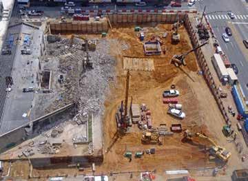
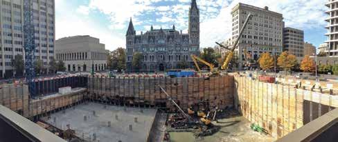
Taken from the pediatric care building, excavation, and SOE at the start of mat foundation construction. Historic Old City Hall is in the background. Courtesy of Skanska USA. Schematic of the system of underpinning and bracing below the existing pediatric care building.
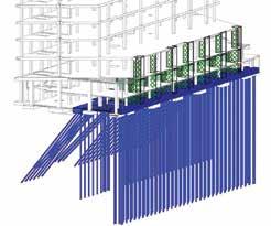
0.42; and limiting chloride ion penetrability to 1,000 coulombs in 28 days per ASTM C1202. Typical gravity columns were 36 inches by 36 inches using 8,000 psi compressive strength concrete at the lower levels. ASTM A615 Grade 65 KSI reinforcing steel was used in the columns to assist with rebar congestion at beam intersections and column splices. The six outpatient floors plus mechanical penthouse were constructed to accommodate the addition of another seven levels above. Typical floor slab construction consisted of 3.5 inches of lightweight concrete over a 2-inch composite deck for a two-hour fire rating. While typical 30-foot by 30-foot bays of all clinical levels were framed with W16 beams and W24 girders, the first steel level above the concrete framing had beams as deep as W33 connecting into W36 girders in order to meet vibration requirements for sensitive imaging equipment. Steel-braced frames in the upper levels align atop CIP concrete shear walls of the parking levels to provide lateral force resistance. A Seismic Response Modification Coefficient (R) value of 3.0 was used to avoid prescriptive joint design requirements of AISC 341. Wind loads for this structure were close in value to seismic forces so there was little to gain by using a larger R-value.
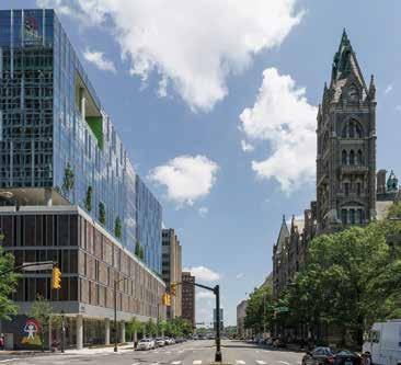
The completed Pavilion stands at the northwest corner of East Broad Street and North 11th Street in Downtown Richmond, Virginia. Courtesy of Michael Stavaridis. The Sky Lobby is constructed on the uppermost level of CIP concrete framing. This portion of concrete framing is depressed several feet to accommodate the depth of planters and allow for the structural slabs to slope to drains. The floor system was designed for heavy concentrated loads of landscaping boulders, as well as a 20,000-pound allowance for mature trees in each planting well.
Conclusion
In the second decade of the 21st century, few projects have as much social resonance as those connected with health care and those connected with children. This one exemplifies the best of both. The new Children’s Pavilion opened on March 21, 2016, to the kind of enthusiasm one might expect when outpatient pediatric services expand from a 54,000-square-foot facility well past its prime to a gleaming high-tech tower housing clinics, radiology, same-day surgery, lab testing, dialysis, infusions, family amenities and more, in an environment custom-tailored for kids. Even before construction was finished, the Pavilion had been recognized for its innovative design. Awards include the 2013 Honor Award of Excellence in Architecture (AIA Richmond Chapter), 2014 National Healthcare Design Award (AIA Academy of Architecture for Health), 2015 Future Healthy Built Environment Award (Design & Health International), and 2015 Concrete Excellence Award (American Concrete Institute Virginia Chapter). By the time it was completed after five years of planning and preparation, compiled data spoke volumes about the scope of this undertaking: $200 million invested, 2,450 tons of steel, 523,000 pounds of sheet metal, 41,000 cubic yards of concrete, seven floors of structured parking, and 83 new exam rooms. Now, after more than a year in operation, the building has become a downtown Richmond landmark, revitalizing the historic and vital Broad Street corridor as it has improved the lives of many children and their families. After all, that is something worthy of support.▪ Nathan C. Dumas, P.E. (ndumas@schnabel-eng.com), is a Geotechnical Engineer with Schnabel Engineering in Glen Allen, VA. Jeffrey S. Davis, P.E. SECB, LEED AP BD+C (jdavis@dmwpv. com), is a Structural Engineer with Dunbar Milby Williams Pittman & Vaughan in Richmond, VA. Donna E. Adams, P.E. SECB (dadams@dmwpv.com), is a Structural Engineer with Dunbar Milby Williams Pittman & Vaughan in Richmond, VA.


