10 minute read
Product Watch
Repair of Columns with FRP Laminates
By Mo Ehsani, Ph.D., P.E., S.E., Majid Farahani, P.E. and Eric Raatz, P.E.
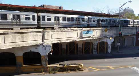
Loss of load-carrying capacity in columns and piles in bridges is a major concern worldwide. In coastal regions, the dry-wet cycles lead to corrosion of reinforcing steel in concrete piles and bridge piers. In cold climates, the use of deicing chemicals results in corrosion of steel. Figure 1 shows one of many such cases in Chicago where reinforced concrete columns are severely weakened by corrosion and steel trusses have been added to carry the load. Similarly, in industrial facilities such as mines, aggressive chemicals cause premature corrosion of steel columns. Thousands of wooden utility poles weakened by infestation break each year during hurricanes and tornados. Many old bridges are supported on timber piles. Due to recent successes in cleaning the waterways, marine borers have returned and the timber piles are deteriorating at alarming rates. These scenarios all require efficient techniques for in-situ repair and retrofit. The ideal solution will not only replace the loss in strength due to decaying materials, but should create a stronger and more durable structural element. The concept of repair and retrofit of structures with FRP was first introduced by the principal author in the late 1980s (Ehsani and Saadatmanesh, 1990). In the ensuing years, the same researchers received the first grant awarded by the NSF to study retrofit of bridge piers with Fiber Reinforced Polymer (FRP) products (Saadatmanesh et al. 1996). That study, and many others that were conducted worldwide in the following years, have undeniably demonstrated the effectiveness of FRP in strengthening deteriorated columns. A large number of columns in buildings and bridges have been retrofitted with this technique worldwide. All those studies and field applications use the wet layup technique, whereby fabrics of carbon or glass are saturated with resin in the field and wrapped around the column. However, there are several shortcomings with that technique. The flexibility of the fabric requires that the surface of the host structure be repaired to a smooth surface before the fabric can be wrapped onto the column. This prolongs the repair time. Similarly, the flexible fabric cannot
Figure 1: Corrosion-damaged concrete piles in Chicago being assisted with steel trusses.
be bonded to wooden piles that have an uneven surface. The wet layup is also useless for repair of steel column shapes.
FRP Laminate
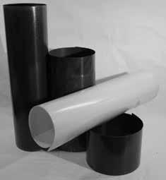
To overcome the above shortcomings, a new form of FRP laminate has been developed (Ehsani, 2010). During the manufacturing process, one or more layers of carbon or glass fabric are saturated with resin and subjected to heat and pressure to construct pre-cured laminate sheets as thin as 0.01 inches. The precision required to produce such a thin laminate was one that was finally achieved after an extended R&D process. The laminates are 4 to 5 feet wide and are supplied in rolls as long as 300 feet. The tensile strength of these laminates ranges between 60,000 and 155,000 psi depending on the number of layers of fabrics and the orientation of the fibers. Unlike the wet layup system, the laminates are stiff enough to stand on their own (Figure 2). In the field, an appropriate length of the laminate is cut and wrapped around the deteriorated column to create a structural shell that is not bonded to the host column. A thin layer of epoxy is brushed over the overlapping portion of the laminate to create a two- or three-ply shell in the field – similar to a sonotube. The annular space between the shell and the host column is filled with resin or grout to make the host column and the shell work compositely.

Advantages of the New System
FRP laminates offer several advantages over conventional methods and materials used for repair of columns and piles. In the field, the laminates are usually wrapped two times and epoxy is applied in the overlapping portion to create a seamless shell around the column. From a structural behavior point of view, the combination of high tensile strength of the laminates and the creation of a seamless shell results in a tube that offers very high confining pressure for the grout and
Figure 3: Repair of steel poles at TEP substations: original repair concept; corroded pole; filling the pole with grout; reinforcing steel welded to base plate; applying epoxy to the laminate, wrapping it around the pole and holding it with straps while grout is placed; finished and painted jacket.
the pile. The magnitude of this confining pressure depends on the strength of the laminates and the number of plies that are incorporated in forming the shell in the field. For example, if a concrete pile constructed with 4000 psi concrete is encased in a laminate jacket that offers a confining pressure of 600 psi, the confinement results in a rise of concrete compressive strength from 4000 psi to 6600 psi. In the wet layup FRP systems, it is customary to prepare coupons (witness panel) of the installed fabrics each day. These coupons are later shipped to a qualified laboratory for strength verification. However, by the time the results become available, the project is most likely completed, making any remedial measures difficult to implement. In contrast, the laminates can be tested in advance and any substandard roll can be rejected. From a construction point of view, the laminates can be made into endless geometrical shells in the field; this eliminates time and expense of ordering customized jackets in advance and speeds the repair process. Similarly, shipping and storage costs are reduced. The light-weight laminates require no heavy equipment for handling, and the entire repair kit and necessary tools fit on a typical pickup truck. This eliminates traffic controls and, in most situations, reduces labor, equipment, and associated delays and expenses. FRP laminates also serve as a moisture barrier, protecting the grout and the host column from future deterioration. Even in cases where reinforcing steel is placed within the annular space, there is no need to provide substantial concrete cover for the reinforcing bars. This, combined with the ability to build the jacket to any size in the field allows construction of snug-fitting jackets that minimize the volume of grout needed for repair. In certain applications, for example when a concrete or wooden pile is embedded in soil, the repair can be completed with no open cut trenches. The shell is first created above ground and is free to slide up and down along the height of the pile. Next, high pressure water or an air jet is used to remove a 1-inch ring of soil adjacent to the pile. Then the shell is lowered along the pile into its final position and the annular space is filled with resin or grout. Similarly, in repair of underwater piles, it is possible to construct the jacket on the portion of the pile above the waterline and gradually lower the jacket into the water as it is being constructed. Moisture insensitive epoxies are used in such applications to allow curing of the epoxy in water. Such repairs can eliminate the use of costly divers and result in significant cost savings. FRP laminates are non-metallic and will not corrode. They offer a long service life with little maintenance. The laminates are ideal for repair of deteriorated concrete or wooden piles and utility poles. In such applications, it is best to inject a low viscosity resin in the annular space. The resin can be pressurized to penetrate into the voids and crevices of the concrete or wood for enhanced structural performance and elimination of decay from the environment and insects.
Field Application
There are several different structure types within Tucson Electric Power Company (TEP) substations that are typically constructed with galvanized 10- x10-inch hollow steel tubes (HSS). Due to improper drainage, moisture from rainwater is trapped inside the tubes and causes significant corrosion near the base of the structures. Figure 3 shows a typical HSS where the corroding steel has been scraped off and removed from the inside face of the pole. Earlier attempts to remedy the problem called for steel plates that were externally bolted to the lower 3-feet of the structures (Figure 3). However, these repairs would hide the corroded portion of the structures from view and inspection, while the corrosion process continued inside the poles. Rather than replace the structures, use of the FRP system enabled the structures to be repaired in place and resulted in continuing system reliability. With proper oversight of safety personnel, the structures could be repaired without need for a costly outage. The repair of the poles with laminates was aimed at strengthening the lower 3 feet of the structures. An access port about 3 inches in diameter was cut at an elevation of 33 inches from the base. All loose rust was removed from inside the structure and the openings were temporarily sealed with plywood and clamps. A non-shrink high-strength grout was mixed and pumped into the structure from the access port. Four No. 5 U-shaped reinforcing bars were welded to the base plate; these bars were primarily for enhanced flexural capacity of the structure.

Figure 4: The I-70/I-270 interchanges in St. Louis, MO where 49 corroded bridge piling were recently repaired with FRP laminates.
Due to its dielectric properties, a glass laminate with tensile strength of 62000 psi and thickness of 0.026 inch was used. A 3-foot wide x 8.5-foot long piece of laminate was used for each structure. A special two-component epoxy was mixed in the field and applied to an approximately 5-foot long section of the laminate. The mixed epoxy has a paste-like consistency and is applied with a trowel to a thickness of 20-30 mil. The laminate is then wrapped loosely around the structure to create a two-ply shell. The 8.5-foot length of the laminate allows creation of a two-ply 15-inch diameter shell with 8 inches of overlap beyond the starting point. At this stage, before the epoxy cures, ratchet straps must be used to hold the shell in the desired shape. A 1-inch diameter PVC pipe was installed to make sure no rain water will accumulate inside the structure. The bottom edge of the jacket was sealed with tape atop the base plate. Grout was placed into the shell form. Consolidation of the grout was completed with a small vibrator and the top of the grout was finished with a trowel. Before the grout sets, the hydrostatic pressure from the grout pushes the inner layer of the jacket outward against the outer layer and forces the two plies of the laminate to be tightly pressed against each other. After several hours, the ratchet straps were removed and the exterior of the shell was painted. All of these repairs were performed while the substation remained fully operational. A similar approach was used to repair 49 steel H piling in four bridges at the intersection of I-70 and I-270 in St. Louis, MO (Ehsani and Croarkin, 2011). Routine inspections had resulted in lowering the substructure condition rating of this bridge to poor (National Bridge Inspection rating of 4 on a 9 point scale). This meant these bridges were considered Structurally Deficient due to the number of piling with significant section loss (Figure 4). The repairs were completed in just two weeks, improving all four bridges to a Satisfactory Condition Rating (NBI rating of 6). All of this was affordable enough to be funded with the region’s operations budget, and repairs took place on one of the busiest highways in Missouri without causing any delays or distractions to the traveling public. FRP laminates have been used on other projects, including the repair of underwater concrete piles in a condominium building in Miami, FL. They are currently being considered for repair of timber bridge piles and utility poles. The numerous applications attest to the unique features of this product.▪ Mo Ehsani, Ph.D., P.E., S.E. is Professor Emeritus of Civil Engineering at the University of Arizona and President of QuakeWrap, Inc., Tucson, AZ. He may be reached at Mo@QuakeWrap.com. Majid Farahani, P.E. is Civil/ Transmission Engineering and Standards Supervisor at Tucson Electric Power Company, Tucson, AZ. He may be reached at MFarahani@TEP.com. Eric Raatz, P.E. is Civil/Transmission Engineer at Tucson Electric Power Company. He may be reached at ERaatz@TEP.com.
The online version of this article contains detailed references. Please visit www.STRUCTUREmag.org.


