30 minute read
Construction Issues
On a recent chemical plant project for which the author was the Engineer of Record, an electrical contractor, contrary to contract specifications, manually arc welded electrical grounding conductors to reinforcing steel for a pipe rack foundation. The electrician explained that the National Electric Code (NEC) allows welding to concrete encased reinforcing steel, and he frequently does so in lieu of independent electrical ground rods which were specified on this project. Paragraph 250.52 (A) (3) Concrete-Encased Electrode of the NEC does permit welding to reinforcing steel. However, NEC does not reference AWS D1.4/ D1.4M Structural Welding Code-Reinforcing Steel or provide any guidance to the special rules, regulations, and procedures prescribed by AWS D1.4/ D1.4M. If AWS D1.4 is not followed for manual arc welding reinforcing steel, the structural integrity of reinforced concrete may be jeopardized. Unfortunately, this particular contractor did not conform to D1.4 and the reinforcing steel was encased in concrete before a visual inspection could be conducted. This article covers AWS requirements for welding reinforcing steel in reinforced concrete applications. It summarizes the main themes of the various sections as they pertain to welding reinforcing steel and contains guidelines for working with the body of rules and procedures for structural welding of reinforcing steel to reinforcing steel, welding reinforcing steel to structural steel, and welding reinforcing steel to electrical grounding electrodes. Implications to improve future projects are also addressed. Fusion welds in shop fabrication of reinforcing steel and CADWELDs are outside the scope of this article. Electric resistance welds found in the fabrication process of welded-wire reinforcement are conducted by computer controlled welding machines within a controlled environment. A combination of pressure and heat generated by electric impulses fuse intersecting wires together. Shop personnel are never engaged in the actual welding process and no filler material or other foreign matter is introduced. CADWELDs do not apply because the steel-filled coupling sleeve of a CADWELD is a mechanical splice in which molten metal interlocks the grooves inside the sleeve with the deformations on the reinforcing bar. Weldability of reinforcing steel and compatibility of welding procedures need to be considered and closely supervised when manual arc welding of reinforcing steel is required. Weldability is determined by the chemical composition of steel and described by the Carbon Equivalent (CE) number. Carbon is the primary hardening element in steel. Hardness and tensile strength are inversely related to ductility and weldability. As carbon content increases up to 0.85%, so does hardness and tensile strength. As carbon content decreases, ductility and weldability increases. CE is an empirical value in weight percentages, related to the combined effects of ConstruCtion
different alloying elements used in making carbon isteel, of an equivalent amount of carbon. This value can be calculated using a mathematical ssues equation. The lower the CE value the higher the weldability of the material. The welding Code provides two expressions for calculating CE. The first expression (Equation 1) only considdiscussion of construction issues and techniques ers the elements carbon and manganese, and is to be used for all bars other than ASTM A706 material. A second more comprehensive equation (Equation 2) is given for ASTM A706 and considers carbon, manganese, copper, nickel, chromium, molybdenum, and vanadium content. Chemical composition is obtained through certified mill test reports or independent chemical analysis. Chemical composition varies for each production run, so it is important to obtain the analysis that matches the specific material to be welded. Once the CE number is calculated, the minimum preheat and interpass temperature is deter- Welding Reinforcing Steel mined from Table 5.2 of the Code. If material test reports are unavailable and chemical composition AWS D1.4/D1.4M:2011 is not known, which is particularly common in alterations and building additions of existing By John Hlinka, P.E. structures, the Code prescribes the highest preheat and interpass temperature for desired reinforcing bar size: 300° F (150° C) for number 6 bars and smaller, and 500° F (260° C) for number 7 bars and larger. If the chemical composition for ASTM A706 is not known or obtained, then preheat and interpass requirements are somewhat relaxed; no preheat is required for number 6 bars and smaller, 50° F (10° C) for number 7 to number 11 bars, and 200° F (90° C) for number 14 and larger. John Hlinka, P.E., is Senior Project As with all welding, when the material is below Manager/Structural Engineer at 32° F (0° C), the Code prescribes the material QualEx Engineering in Paducah, to be preheated to at least 70° F (20° C), and Kentucky. He can be contacted at maintained during the welding process. jhlinka@qualex.com. CE = %C + %Mn/6 (Equation 1)
CE = %C + %Mn/6 + %Cu/40 + % Ni/20 + %Cr/10–%MO/50–%V/10 (Equation 2) Standard specifications for low-alloy steel ASTM A706 limit chemical composition and CE to enhance weldability. However, it is permissible to weld other base metals, such as ASTM A615, which is commonly used in reinforced concrete, as long as the appropriate weld procedure specification (WPS) is followed and correct filler weld metal is used. Many other permissible base metals are listed under paragraph 1.3.1 of the Code. High strength reinforcing steel such as ASTM A615 material is susceptible to cracking when not adequately
The online version of this article contains detailed references. Please visit www.STRUCTUREmag.org.
Material Grade
Rebar Size Chemical Analysis (Percent) C Mn P S Si Cu Cr Ni Mo Cb V CE
Preheat Temp. °F (°C)
ASTM A615 #7 0.39 1.00 0.018 0.037 0.21 0.39 0.20 0.13 0.038 0.00 0.00 0.56 200 (90) ASTM A706 #7 0.28 1.18 0.028 0.028 0.17 0.29 0.19 0.09 0.02 0.00 0.24 0.48 50 (10)
Sample mill test report data with calculated CE numbers and minimum preheat and interpass temperatures from Table 5.2 of AWS D1.4.
preheated. Welding of ASTM A615 material should be approached with caution, since no specific provisions have been included to enhance its weldability. The Table compares chemical composition, CE, and preheat temperatures for sample ASTM A615 and ASTM A706 materials. As shown, the preheat requirements are lower for A706 than A615 material. A lower carbon percentage and the addition of molybdenum and vanadium contribute to a lower CE number for A706. Bar size also is considered in determination of preheat temperature. The smaller the bar size, generally, the smaller the preheat temperature. With all rebar welding, allow bars to cool naturally. Never accelerate cooling; accelerated cooling will change the metallurgy of the reinforcing steel. Sections 2 and 3 of the Code provide allowable stresses and structural details, respectively. A wide range of details are provided, including Direct Butt Joints, Indirect Butt Joints, Lap Joints, and Interconnection of Precast Members. The effects of eccentricity should be considered when designing Lap Joints, if external restraint is not provided. AWS D1.4 does not provide details for welding reinforcing steel to electrical grounding conductors. If unavoidable, the author suggests using the CADWELD method to attach the grounding conductor to an ASTM A36 plate and then using the AWS Lap Joint detail to attach the plate to the reinforcing
Software and ConSulting FLOOR VIBRATIONS
FLOORVIBE v2.10
• Software to Analyze Floors for Annoying Vibrations • New release • Demo version at www.FloorVibe.com • Calculations follow AISC Design Guide 11 Procedures • Analyze for Walking and Rhythmic Activities • Check floors supporting sensitive equipment • Graphic displays of output • Data bases included CONSULTING SERVICES
• Expert consulting available for new construction and problem floors. Structural Engineers, Inc.
steel, or CADWELD the conductor directly to the reinforcing steel. Other mechanical type attachments provided by NEC are preferable to manual arc welding. Section 4 of the Code addresses workmanship in regards to preparation of base metal, joint assembly, distortion, and quality. Welding of bars which cross and welding within two bar diameters from the points of tangency for the radius of bent bars are not permitted. Cross bar welding can lead to local embrittlement of reinforcing steel. When welding on bars that are already embedded in concrete, allowances must be made for thermal expansion of the steel to prevent spalling or cracking of concrete or destruction of the bond between the concrete and steel. Acceptable and unacceptable fillet and grove weld profiles are illustrated in Section 4 of the Code. Section 5 of the Code discusses welding technique. Technique includes selection of filler metal, minimum preheat and interpass temperatures, welding environment, arc strikes, cleaning, progression of welding, coated base metal, and welding electrodes. Allowed welding processes include shielded metal arc welding (SMAW), gas metal arc welding (GMAW), or flux cored arc welding (FCAW). Other processes maybe used when approved by the Engineer of Record. Special storage conditions are required for low-hydrogen electrodes. Low-hydrogen electrodes must be purchased in hermetically sealed containers or must be baked prior to use.
Selection of correct welding electrodes which are compatible with base metal material is critical. An incorrect choice may lead to micro cracking in the heat affected zone, which may lead to joint failure. Generally speaking, tack welds are prohibited unless they conform to all design and control requirements of D1.4.
Tack welding can create a metallurgical notch effect and weaken a bar at the weld.
Sections 6 and 7 of the Code pertain to welder qualifications and inspections, respectively. All structural welding must be performed by qualified welders. WPS qualification by testing must include specific joint type and size to be welded. Inspectors must also be qualified. Acceptable qualifications include AWS certification, Canadian Welding Bureau certification, or an Engineer/Technician trained or experienced in metal fabrication, inspection, testing, and who is competent to perform inspection work. It is not unusual for the Engineer of Record to request evidence of welder qualifications prior to starting a project. Annex A of the Code includes the following sample forms for informational purposes: Procedure Qualification Record (PQR), Welding Procedure Specification (WPS), and Welder Qualification Test Record.
Conclusion
Welding of reinforcing steel should be approached with caution to prevent cracking of base metal and potentially jeopardizing the integrity of a reinforced concrete foundation or structure. AWS D1.4/D1.4M covers the design, workmanship, technique, qualification, and inspection requirements for welding reinforcing steel in most reinforced concrete applications. NEC paragraph 250.52 (A) (3) allows welding of electrical conductors to reinforcing steel without reference to AWS D1.4/D1.4M. Electrical contractors can potentially damage the structural integrity of reinforced concrete foundations if the requirements of AWS D1.4 are not followed. Proposed Tentative Interim Amendments (TIAs) were submitted to the NFPA Standards Council on August 6, 2013. Hopefully, the NFPA Standards Council will adopt these amendments. In the case presented at the beginning of this article, the minimum amount of reinforcing steel required by ACI 318 provided greater than two times the strength needed for design loads. Therefore, if the integrity of one reinforcing bar was reduced, the foundation would still be structurally adequate. The author suggests that a note be added to future concrete drawings that specifically prohibit welding of electrical conductors to reinforcing steel without the approval of the Engineer of Record.▪
Solid Performance Shear Versatility



Introducing the newest addition to our shearwall family – the Strong-Wall® SB shearwall. It combines performance – high load values – with versatility – it’s trimmable in the fi eld. The SB wood prefabricated shearwall offers greater lateral-force resistance for many applications, including narrow and tall wall spaces and garage portals. In seismic and high-wind areas, the SB wall is comparable to the strength of narrow steel shearwalls. For a high-performance, versatile and economical solution, specify the Strong-Wall SB shearwall. Learn more by calling your local rep at 800-999-5099 or visiting strongtie.com/sb.


Concrete “Paint” Arrests Cofferdam Corrosion at Submarine Pier

By Brian Robinson, P.E.
Each year, the American Society of Civil Engineers (ASCE) publishes a Report Card for America’s Infrastructure. Th eir rating system uses familiar academic grading (A through F) to report on the condition of America’s aging infrastructure. Last year, America’s infrastructure received a D+, indicating deteriorating infrastructure. Included in this report are waterfront structures, which are vitally important. According to ASCE, America has over 3,700 maratime terminals serving as commerce and transportation hubs. Often, steel sheet pile walls are incorporated as part of cost-eff ective waterfront earth-retaining structures for these harbors. Many of these walls are subjected to salt-water exposure, tidal fl uctuations, and a host of other environmental factors that accelerate corrosion. Even if the coatings are maintained and a cathodic protection system is employed, the corrosion near the waterline eventually necessitates expensive repairs and, often, replacement of the structure. Cellular sheet pile coff erdams are particularly diffi cult to repair because of the lack of redundancy in the tensioned cell walls. Th is article highlights a unique method to repair a cellular coff erdam using a reinforced concrete facing installed over the aging sheet piling.
Existing Structure Confi guration
Th e submarine pier is located in the Hood Canal waterway in Washington State’s Puget Sound region. Considered a vital natural resource, Hood Canal provides vessel passage and is home to many aquatic species, some of which are fi shed for human consumption. Th e triangular shaped pier, accessible from land by two pile-supported trestles serves as a vessel docking-surface on two sides and a dry dock is integrated into the third side of the triangle (Figure 1). Th e concrete deck supports gantry cranes, mooring hardware, and a number of buildings. Most of the deck is supported by concrete piles, but portions are supported by a coff erdam that surrounds the dry dock structure. Th e coff erdam is formed by a series of circular interlocking steel sheet pile cells that form the outer perimeter of the dry dock structure. Th ese sheet piles were vibrated or driven into the underlying seabed, and
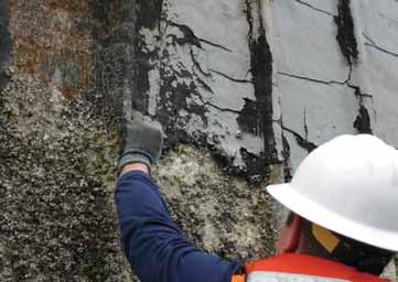
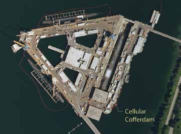
Figure 1: Submarine pier aerial view. Courtesy of the U.S. Geological Survey. each cell was backfi lled to form a cylindrical earth retaining structure. Additional sheet pile arcs connect each cell. In total, the dry dock uses 20, 75-foot diameter cells connected by 19 arcs in a U-shaped pattern that forms three sides of the dry dock structure. Th e fourth side is open to accept vessels and confi gured to accept a caisson (gate) that closes the dry dock off from the surrounding water. Th e internal cast-in-place concrete dry dock walls envelope portions of the coff erdam cells and arcs. However, at the outer perimeter, the sheet pile walls are fully exposed to the marine environment above and below the water line.
Field Observations
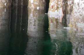
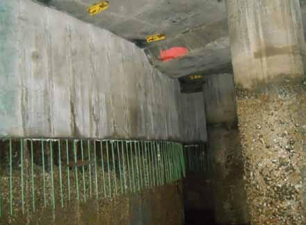
Th e fi rst step in developing a comprehensive design strategy was to perform fi eld investigations of the existing pile condition. From boat- and deck-based observations, the design team documented the condition of each exposed sheet pile face and noted special conditions that would need to be considered through the design process. Th e existing coatings were in a state of failure at most locations (Figure 2). Th e facility was equipped with an active cathodic protection system that consisted of anodes suspended from cantilevered beams extending over the coff erdam face. It is important to note that this type of cathodic protection system is fully eff ective only below the low water line, with reduced eff ectiveness in the tidal zone. Th e fi eld observations also illuminated a number of construction constraints that would have otherwise been diffi cult to discern from a review of the design documents alone. Th e most surprising and important constraint was the restricted conditions under the deck. As shown in Figure 3, some existing concrete piles were less than 1 foot from the sheet pile face. Th e number and proximity of existing concrete piles would present a substantial access and construction challenge for under-pier work. Additionally, the design team observed a number of deck-based and water-based operations associated with the day-to-day function of the pier that would present a construction staging and sequencing challenge for the contractor.
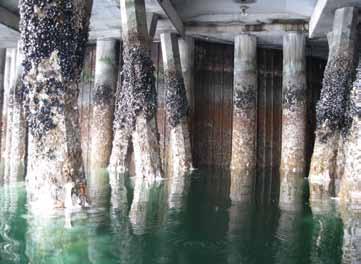
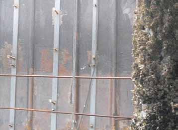
Figure 3: Existing concrete piers in close proximity to the cofferdam wall face. Figure 4: Pre-fabricated welded headed stud rails. Courtesy of Seaward Marine.
Corrosion Mitigation Selection and Design Considerations
The owner considered a number of coating systems to mitigate further sheet pile corrosion: a high performance marine coating, thermal spray aluminum, copper-nickel cladding, and a concrete facing. Due to the considerable durability and low life-cycle cost, the owner chose a concrete facing extending from the top of the cofferdams to two-feet below Mean Lower Low Water as the preferred repair alternative. The owner called for a concrete service life of at least 50 years. Considering the cofferdam pile structure appeared to be performing well and did not exhibit excessive corrosion, the concrete facing would not be structural, but rather would provide an overlay to passivate and protect the steel cofferdam. The concrete facing would present a number of different technical design challenges, but most of them would be related to one central issue: crack control. In this case, the design team had two related tools for controlling concrete cracking: rebar configuration and concrete specification. Rebar Configuration The design team considered that, during drying shrinkage, the formation of a crack requires a point or line of restraint. In this case, the vertical interlock joints between the sheet piles provided that restraint. Each interlock has two nested knuckles that protrude from the face of each sheet by about an inch. This protrusion is the line of restraint where an assumed crack might form. Table 4.1 of ACI 224R indicates a reasonable crack width for seawater spray is 0.006 inches, so this was adopted as the target crack width for the facing. Assuming the crack would form vertically, in-line with the knuckles, the primary reinforcement would be horizontal. Using minimum reinforcement, the resulting calculated crack width was 0.003 inches. Concrete Specification The basis of the concrete design was the owner’s specification for marine concrete with special considerations added for shrinkage control. Considering the non-structural nature of the facing, the concrete would not need to develop especially high compressive strength. This was advantageous because it presented the opportunity to lower the cement content in the mix, which would lower the water content, thereby minimizing shrinkage-induced cracks. This was accomplished by limiting the specified 90-day strength to a range of 3500 pounds per square inch (psi) to 4000 psi. Additionally, the mix incorporated a maximum water/cement ratio of 0.38 and a provision for rapid strength gain with age combined with a low shrinkage requirement. To assure maximum durability in this sea water environment, the concrete mix was proportioned to maximize its resistance to the penetration of chloride ions with a limit of less than or equal to 1000 coulombs at 56 days. The mix was also developed to limit the drying shrinkage to a maximum of 0.03% at 28 days. Special additives were also required in the concrete. Much of the concrete casting was to be done underwater by divers in a bottom-up pumping operation. Due to the strict environmental requirements for working in the Hood Canal, anti-washout additives were required to prevent concrete paste leakage. Also, due to the long travel time and delays getting through the base, a set retarder was used.
Design for Constructability
The contractor would face a myriad of technical and operational challenges during construction of the facing. The following is a partial list of these challenges: • Under-pier access was substantially restricted due to the close spacing of existing concrete piling. • The curvature of the wall face would present a formwork challenge. • The contractor needed to minimize interruption of pier operations. This would restrict construction laydown space and vehicle access. Additionally, the contractor would have to schedule activities around all pier operations. • The construction crew and concrete deliveries would have to pass through checkpoints. • The large distance between the jobsite and the nearest concrete batch plant would make the efficient delivery of concrete even more critical, as the mix is intended to have rapid strength gain as part of the shrinkage control strategy. • The tidal fluctuation is as much as 11 feet, so the work schedule would have to consider tidal conditions. • Due to the presence of protected aquatic species, in-water work was restricted to a 7-month period, called a “fish window”, starting in July. The operational nature of these restrictions made mitigating them by design difficult. Some modest mitigating design strategies included provisions to make construction of the panels as flexible as possible,
like simple rebar layout and coordinating the weldedheaded-stud (WHS) spacing and rebar spacing to minimize the amount of additional rebar. Prior to construction, the designers and contractor also conducted a constructability meeting to review the design. This resulted in a number of adjustments: • Welded headed studs were pre-fabricated on steel bars, which were then fillet welded to the sheet pile face (Figure 4, page 27). Considering the large number of WHS’s on project, this would save substantial time by minimizing layout and welding time in the field, some of which had to be done under water by divers. • To more easily accommodate the in-water Figure 6: Completed cell and arc facing. Courtesy of Seaward Marine. construction restriction, the contractor implemented a horizontal cold joint, which broke the and under-pier work. Cores were taken of the test wall segment to facing into “uppers” and “lowers.” This would allow the measure specific gravity, chloride ion penetration resistance, voids, contractor to pour the “lowers” when in-water construction and compressive strength. Additionally, it was an opportunity to was allowed and could continue construction above-water evaluate the cracking at specific concrete ages. Figure 6 shows a typion the “uppers” between the fish windows. Figure 5 shows cal cell and arc with completed “uppers” and “lowers.” The test wall a completed “upper” in an under-pier condition. The only was a success and remained as a permanent part of the facing. After changes required to accommodate this configuration were a the test wall was approved by the owner, the contractor constructed minor modification to the welded headed stud layout at the the project faster than expected, allowing it to be finished ahead of cold joint and the implementation of epoxy-coated vertical schedule. During the last on-site observation, the facing appeared bars, at the joint locations only. to be performing very well and very few cracks have formed. As you might expect, the owner is very pleased with this outcome.

Test program and Completion
Since the construction of the facing panels would be so difficult, contract documents included provisions for a test wall segment. This would mitigate risk in two ways. One, it would give the contractor the opportunity to refine the construction process while including provisions in the budget to re-construct the wall if necessary. Two, it would give the owner and designers the opportunity to inspect the wall and adjust the design if necessary. The test wall segment would be constructed with the intent to remain as the first section of the wall if all tests and inspections were acceptable. The wall segment was located to capture a representative collection of all the different existing conditions, including one cell, one arc, the cell-arc joint,
Conclusion
This project demonstrated the successful use of what amounts to a thick coat of “paint” made of high-tech concrete to repair an aging sheet pile cofferdam located at a very challenging site. While more expensive to install than other coatings, this solution is estimated to offer the greatest long-term durability and lowest lifecycle cost. Additionally, this solution was installed with relatively little impact to the facility operations. With America’s infrastructure, including over 300 harbors, in a deteriorating state (remember that D+?), having cost-effective and flexible strategies to mitigate corrosion while minimizing day-to-day facility operations is imperative. If you find yourself faced with a replace or repair scenario on a quay wall or cofferdam, consider using a concrete facing to extend the structure’s life. After going through this project, I’d give the strategy an A.▪ Brian Robinson, P.E., is a Project Engineer in the structural group at KPFF Consulting Engineers in Seattle. He specializes in excavation shoring and was a design engineer on the cofferdam repair project. Brian may be reached at brian.robinson@kpff.com.
Project Team
Owner: US Navy Structural Engineers: KPFF Consulting
Engineers, Seattle, WA Cathodic Protection Engineers: Norton
Corrosion, Woodinville, WA General Contractor: Seaward Marine,
Chesapeake, VA






GEOPOLYMER PRECAST FLOOR PANELS


Sustainable Concrete for Australia’s Global Change Institute

By Rod Bligh, B.Eng, MSc, CPEng, FIEAust and Tom Glasby B.Eng (Civil), MBT, MIEAust, CPEng, RPEQ
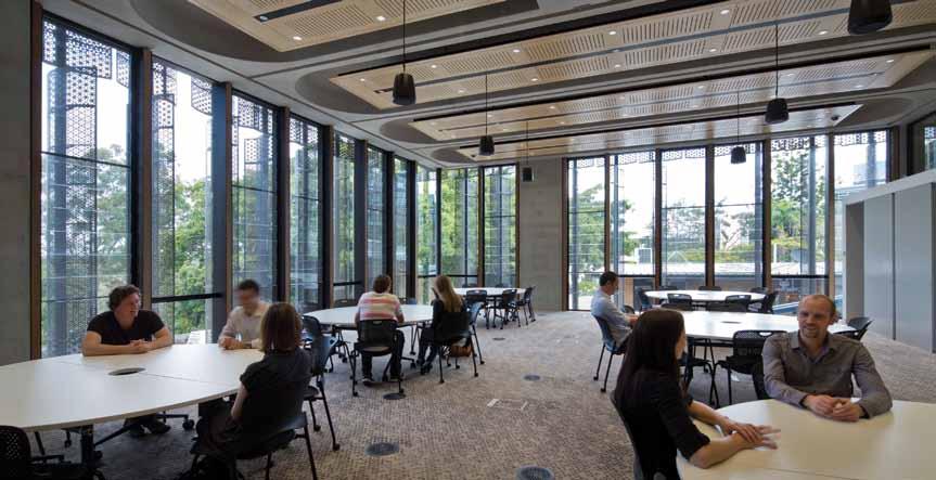
Figure 2: Panel soffi t with ceiling service panel installed. Courtesy of Angus Martin.
The Global Change Institute (GCI) is an Australian organization within Th e University of Queensland (UQ) that researches global sustainability issues including resource security, ecosystem health, population growth and climate change (Figure 1). Th e design of its new $32 million (AUD) building by project architects, HASSELL and structural and façade engineers, Bligh Tanner, was to be an exemplar project benchmarked using the Green Building Council of Australia’s Green Star rating (at 6 Star Green Star level), as well achieving an Australian-fi rst Living Building Challenge compliance. Th e Living Building Challenge is an international rating system based in North America that explores a broader basis of sustainability, assessing the seven performance areas of site, water, energy, health, materials, equity and beauty. Further design parameters set for the project were zero net carbon emission for building operation, carbon neutral with carbon off set.
Design process
Early in the design, the structural engineering team explored the potential for the incorporation of structural timber. Th e work at the University of Technology, Sydney, developing and testing
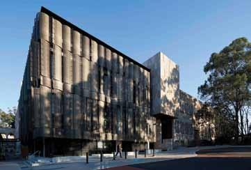
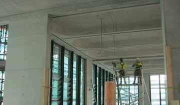
Figure 3: Global Change Institute – vaulted panel soffi t. Timber-Concrete Composite (TCC) fl oors, was of interest and was proposed as a potential fl oor system that combined the benefi ts of timber framing with the acoustic, fi re separation and wearing properties of concrete (Figure 2). It was at this stage that the strong potential for use of geopolymer concrete in the system was identifi ed, as the structural topping would be working at low stress and precasting of the TCC panels would enable quality control in a factory environment. Use of precast was also recognized as advantageous considering the very limited site. Th e design of the passive and low energy thermal control systems was developing at the same stage, and was pushing the fl oor systems toward high thermal mass with active heat exchange by the pumping of air or water through a concrete slab system. Th e next logical iteration of the design was to precast geopolymer concrete fl oor panels with incorporated hydronic pipes coils. To maximize the eff ectiveness of the radiant heat transfer from the concrete, the soffi t needed to be exposed with maximum surface area. Th is then led to the development of vaulted soffi t panels, which were both visually appealing, of high thermal effi ciency and refl ected light down onto functional spaces (Figure 3). Suspended ceiling panels contained lighting, communication technology and sprinklers. Various forms of the 11-meter-span (36-foot) panels were explored, which allowed for air distribution in a plenum/services void above
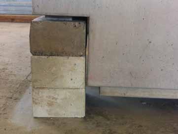
Figure 4: Support at the panel end during the full-scale test.
the panels. The exposed concrete frame, which supports the precast geopolymer concrete panels, was designed to incorporate the air distribution system, which supplies the plenum. Bligh Tanner made contact with Wagners who were developing a geopolymer concrete product branded Earth Friendly Concrete (EFC). Wagners had undertaken some preliminary testing at the time to produce an initial summary engineering report that would ultimately lead to further verification testing for compliance with AS3600 (Australian Standard for Concrete Structures). Although the use of geopolymer was so novel that it would not gain any additional Green Star points in the Material category, The University of Queensland, as the client, understood the significance of the innovation which went beyond Green Star rating. Wagners were asked to fast track the reporting and testing, with a critical cut off date for the interim research report to be indicating whether or not the use of geopolymer concrete on the project was viable. The Green Star submission, which is currently being assessed, includes two Innovation points for the use of the geopolymer concrete on the basis of being a world-first innovation and exceeding the Green Star benchmarks. A positive interim report was delivered during the design period. The only issue identified as a potential concern relative to normal concrete was carbonation resistance; however, this was not considered to be of significance in this case as it was for internal use only. Subsequent testing has shown that rate of carbonation for the mix design adopted is similar to normal concrete incorporating blended cement. At this point, the project consultants accepted geopolymer concrete as the preferred option for the precast floor beams used in the three suspended floors. An additional concern was the ability to supply the geopolymer concrete to the precast fabricator, and also for the precast fabricator, to be willing to take on the risk of working with a new product. The design team and Wagners worked closely with Precast Concrete to ensure that the process was feasible. Bligh Tanner stipulated that a full-scale load test (up to maximum working load) could be undertaken on a panel to confirm the strength and deflection were as predicted. This was considered prudent given the world-first application of modern geopolymer concrete for suspended construction.
Compliance Testing
Geopolymer concrete was included in the design for the 33 precast floor beams (320m3 ≈ 419 c.y.) that formed three suspended floors in
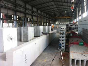
Figure 5: Full scale load test at precast factory.
the building. The specification for the geopolymer concrete in these beams relied on: • Testing key material properties referenced in AS3600. • Independent engineering verification that the tested results showed structural performance properties equivalent to the design basis for design reinforced concrete dicated in AS3600. All tests were undertaken by Wagners Technical services, in some cases using external laboratories (Figure 4 ). The results were independently assessed by Dr James Aldred of AECOM, who Wagners commissioned to provide the independent certification on the geopolymer concrete. Test samples, with the exception of creep and the fire and load tests, were cast and made from geopolymer concrete used during the supply phase of the project. The relevant Australian Standard test method was used in all cases. Creep was assessed via full scale prestressed beams which were made in 2010 and were monitored under load via the use of internal vibrating wire strain gauges. A fire test was conducted at the CSIRO fire testing station at North Ryde, Sydney prior to the start of the project. The first floor beam panel produced served as the prototype to be load tested. Figure 5 shows that the measured deflection under an equally distributed 10 ton load was 2.85 mm (0.10 inches), slightly less than the predicted 3mm using an uncracked section analysis. The testing program revealed a number of beneficial properties of the geopolymer concrete compared to normal GP based concrete, most notably: • Half the typical 56 day drying shrinkage, at an average value of 320 microstrains • 30% higher flexural tensile strength than a comparison standard concrete • Extremely low heat of reaction These properties would indicate that an improved level of performance would be achieved in a range of typical structural applications.
Practical Aspects
Apart from the design and specification details, the geopolymer concrete was required to meet all of the usual handling requirements involved in batching and delivering concrete. Based on several years of EFC supply to a range of external projects and trials, Wagners were able to demonstrate that the geopolymer concrete could be handled and finished similarly to normal concrete. In the case of filling and compacting precast moulds, the methods are the same
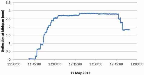
Figure 6: Proto-Type EFC geopolymer beam load test. Figure 7: EFC geopolymer concrete being vibrated into the beam molds, at Precast Concrete Pty Ltd factory, Brisbane.
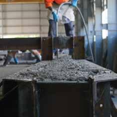
(Figure 6 ). Loads can be batched with all ingredients except the activating chemicals and transported for up to 12 hours to a remote destination in a completely dormant non-reactive state. At the destination, the chemicals are added in a dry powder form directly into the Agitator bowl and mixed on site. While EFC can be produced in normal concrete batching facilities, it is a requirement that GP cement does not contaminate the mix because it causes rapid setting, particularly at higher temperatures. If weigh bins and the like are shared with normal concrete production in a batch plant, then it is possible that the fines of GP cement dust will enter the EFC geopolymer mix in enough quantity to cause variable set times. Another beneficial aspect of geopolymer concrete is its natural off-white finish, is considered a desirable architectural feature. The finished precast geopolymer beams were installed into the building structure during the period of August to October 2012 (Figure 7). Following installation, the precast geopolymer beams were sealed. Several patch trials were carried out to ensure compatibility between the geopolymer concrete and proprietary sealers.
Conclusion
Geopolymer concrete has now moved beyond an emerging technology into the space of a structural concrete that can be designed and used in structures and other applications, as long as the necessary verification and testing is undertaken. The term geopolymer is very broad and encompasses a range of different concretes which may have quite different structural properties. The proprietary geopolymer concrete used in the Global Change Institute building proved to be fully compliant with the structural performance parameters that AS3600 is based on. The use of geopolymer concrete in the multi-storey Global Change Institute building provides an example of how a medium sized engineering consultancy went about assessing a new technology’s ‘fit for purpose’ suitability. It is hoped that this example may provide a path for others to explore new and innovative approaches to structures that improve the sustainability of our built environment. In association with a range of other sustainability innovations utilized in this building, the geopolymer concrete floor beams help to make the Global Change Institute building an outward expression of its inner purpose.▪
Rod Bligh, B.Eng, MSc, CPEng, FIEAust, is a founding director of Bligh Tanner in Australia. Rod may be reached at rod.bligh@blightanner.com.au. Tom Glasby B.Eng (Civil), MBT, MIEAust, CPEng, RPEQ, is a professional engineer and manager in the construction materials group at Wagners. Tom may be reached at tom.glasby@wagner.com.au.
A similar article was presented at the Concrete 2013 Conference, October 2013 in Queensland, Australia. It was also used as a reference document for media releases and other media articles.


