6 minute read
Engineer’s Notebook
aids for the structural engineer’s toolbox
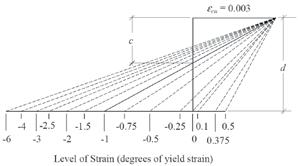
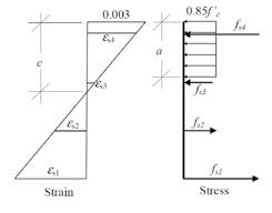
Often a summary refresher helps keep us grounded in the fundamentals of elements that we commonly design. Owing to many requests from peers, this article is provided as a summary of the steps that may be taken for the development of a typical reinforced concrete column interaction diagram. The methodology outlined below reflects the provisions of ACI 318, but it is not the only viable method. In fact, Figure 1: Superimposed series of strain diagrams. ACI 318 does not explicitly require an interaction diagram for column design. However, The result is a strain for each and every bar in the most structural engineers understand that such a column as it correlates to the level of strain that tool is the most convenient form of expressing the was arbitrarily assigned to the layer of reinforcenominal axial and flexural capacities, as well as the ment opposite the compression surface. This also best tool for helping us know how axial loads and helps us know where the theoretical neutral axis bending loads influence and affect one another. for the column is for this strain condition, which Assume, just for the sake of argument, that the occurs where the aforementioned line intersects factored load effect for the design of a tied con- the vertical axis of the strain diagram. Once the crete column is a trivial strain levels and the neutral axis are known, the matter, and that we have design may proceed to the next step. Concrete Column Design the results for Mu and Pu. The next step that we By Hooke’s Law, stress is equal to strain multiplied by the material’s elastic modulus. might follow would be Multiplying the strain for each layer of reinforceto examine a generated ment by 29,000 ksi yields the corresponding Back to the Basics interaction diagram and see whether our inter- stress. This must be truncated to the yield stress active load (represented by Mu and Pu) falls within for any results lying outside of the elastic range By Jerod G. Johnson, Ph.D., S.E. the capacity boundary of our trial column. of behavior for the reinforcement (typically 60 Let us further assume that we do not have the ksi). For the concrete acting in compression, the benefit of an interaction diagram and thus are depth of the compression zone is related to the ‘starting from scratch’. You may recall that an neutral axis by the β1 value, which is a function interaction diagram for a reinforced concrete of f'c and ranges from 0.65 to 0.85 (0.85 for f'c of column may be developed by examining a 4000 psi or less). The stress in the concrete has series of strain conditions at one surface of the a default value of 0.85f'c and is assumed to be column. These strain conditions are arbitrary, and distributed uniformly over the entire compresare selected on the basis of providing the most sion region. Figure 2 illustrates the relationship descriptive capacity boundary that can conve- between the strain and stress diagrams for one Jerod G. Johnson, Ph.D., S.E. niently be determined. At the opposing surface, iteration of interaction diagram development. (jjohnson@reaveley.com), is a an ultimate concrete compressive strain of 0.003 Once the stress in each layer of reinforcement principal with Reaveley Engineers is assigned. This is meant to represent the strain in is known, as well as the dimensions of the + Associates in Salt Lake City, Utah. the concrete at ultimate compressive failure and is concrete compressive stress region, the resulassigned this value regardless of concrete strength. tant forces in each are calculated simply by Figure 1 illustrates the establishment of the fixed multiplying the stresses by the respective areas. 0.003 strain value at the compression edge while Summing the result yields a total force Pn, the layer of reinforcement at the opposite surface the nominal axial capacity of the column as it is subject to a series of strain conditions. The series of strains (tensile and compressive) are then assigned to the layer of reinforcement opposite the concrete compressive failure surface. For any one particular level of strain that we have arbitrarily assigned, we can follow ACI 318 criteria and connect the two opposing points of strain on a diagram with a straight line, thus assuming that the strain is distributed linearly
A similar article was published across with column width. This makes for simple in the Structural Engineers calculation of the strain in the remaining layers
Association-Utah (SEAU) of reinforcement, using the simple formulas Monthly Newsletter (April 2007). It is reprinted with permission. for similar triangles that we learned in high school math. Figure 2: Assumed strain and stress diagrams for reinforced concrete.

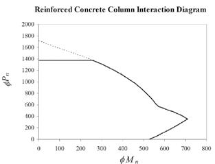
correlates to this level of strain. Multiplying these same forces by their relative distances from the centroid of the gross column section and summing the result yields the nominal moment capacity Mn. Th e fi nal step for this one iteration of design is to determine the strength reduction factor that is appropriate for the level of strain under consideration. Th is is a function of the net tensile strain arbitrarily assigned earlier; it has a value of 0.9 for net tensile strains of 0.005 or more and a value of 0.65 for net tensile strains of 0.002 or less. Intermediate values are linearly interpolated. Th e strength reduction factor is then multiplied by each of the Mn and Pn values calculated previously to determine the resulting φMn and φPn that defi ne this one point on the interaction diagram. Th e entire process is repeated several times, with varying levels of strain assigned to produce a series of points that defi ne the interaction diagram boundary. Figure 1 depicts the superimposed strain conditions as recommended by prominent textbook authors. For each level of strain, the calculations described herein are repeated. For each level of strain, a corresponding point on an interaction diagram can be determined. Interconnecting the points results in the interaction diagram (potentially similar to Figure 3) on which we can plot Mu, Pu and assess whether the column is suffi cient. In summary, the steps for developing a concrete column interaction diagram are: 1) Assign an arbitrary level of strain to the layer of reinforcement opposite the compressive surface and calculate the depth to the neutral axis (c), the depth of the compression stress zone (a), and the level of strain in the remaining layers of reinforcement (using Figure 3: Typical interaction diagram. linear interpolation, similar triangles, etc.). nominal axial capacity (Pn). Multiply 2) Using the ultimate compressive these same forces by their distances stress in the concrete (0.85f'c) and from the center of the section and the dimensions of the compression add the results to yield the nominal stress zone, calculate the resultant fl exural capacity (Mn). Determine compressive force in the concrete. the strength reduction factor and Using the strains in each layer of multiply it by Mn, Pn. Plot the point reinforcement, calculate the stresses φMn, φPn on the interaction diagram. and the resultant forces in each layer 4) Repeat steps 1-3 at least a dozen by multiplying the stress in each layer times, with strain values typically by the area in each layer. ranging from 0.5 to -6, to create 3) Add the resultant concrete force enough points to draw the and the forces in all of the layers interaction curve. Th en, simply of reinforcement to determine the connect the points.▪

ADVERTISEMENT–For Advertiser Information, visit www.STRUCTUREmag.org


