42 minute read
STRUCTURAL ANALYSIS


discussing problems, solutions, idiosyncrasies, and applications of various analysis methods
Seismic building design has typically been based on results from conventional linear analysis techniques. This type of analysis is a challenge for the design of reinforced concrete because the material is composite and displays nonlinear behavior that is dictated by the complex interaction between its components – the reinforcing steel and the concrete matrix. Simplifying the behavior of reinforced concrete components, so they can be modeled using a linear-elastic analysis approach, is vital to our ability to effectively design reinforced concrete structures. Modeling of concrete structural elements using linear analysis to extract a reasonable structural response typically involves modifying the stiffness of concrete structural elements. However, this method presents its challenges, including the following: • Effective stiffness is a function of the applied loading and detailing Effective Stiffness for of the component. Reinforced concrete components behave Modeling Reinforced differently under different loading conditions (e.g. tension, Concrete Structures compression, flexure), as well as different rates of loading (impact, short term, long term). • Applying stiffness modifiers can be A Literature Review an iterative process since the assumed stiffness of reinforced concrete elements in By John-Michael Wong, Ph.D., S.E., a structural analysis model influences the Angie Sommer, S.E., Katy Briggs, S.E., dynamic characteristics of the structure, and Cenk Ergin, P.E. which, in turn, changes the results of the Seismology Concrete Subcommittee of the Structural Engineers Association of Northern California (SEAONC) • analysis and the effective stiffness. Schedule demands pressure engineers to simplify the design process further, leading to only one stiffness modifier per element type applied to many analytical elements. This may be significantly inaccurate for a number of reasons, including: o Analysis models can be very sensitive to the stiffness of a single element, (e.g. backstay effects due to at-grade concrete diaphragms or stiff podium structures in a tall building). o Certain types of elements may have varying stiffnesses due to loading and location. For example, a multi-story column in a tall building will have a higher stiffness at the base compared to the roof. o The design may warrant the consideration of multiple ground motion return periods, such as a service-level earthquake and a Maximum Considered Event (MCE)
The online version of this earthquake, each with a unique set of article contains detailed stiffness properties. references. Please visit This article aids the structural engineer by www.STRUCTUREmag.org. providing a summary of the range of stiffness modifiers recommended by domestic and international publications for a variety of building components. A literature review of codes, standards, and research articles is provided, along with a brief summary of the key assumptions made in each document. Effective stiffness parameters for flexural and shear stiffness are summarized in the Table for easy comparison.
Domestic Codes
A summary of a variety of documents, which were published domestically and are typically used by structural engineers in the United States, is included below. Note that the recommendations provided in each document correlate to specific return periods or hazard events, or specific levels of applied loading. Some recommendations are independent of loading. ACI 318, Building Code Requirements for Structural Concrete ACI 318-11 is referenced by the 2012 International Building Code (IBC). Sections 8.8.1 through 8.8.3 provide guidelines for effective stiffness values to be used to determine deflections under lateral loading. In general, 50% of the stiffness based on gross section properties can be utilized for any element, or stiffness can be calculated in accordance with Section 10.10.4.1. ACI 318-14 contains similar recommendations for stiffness modifiers reformatted in Section 6.6.3. Section 10.10.4, Elastic Second Order Analysis, provides both a table of effective stiffness values independent of load level and equations to derive stiffness based on loading and member properties. Commentary Section R10.10.4.1 explains that these recommendations are based on a series of frame tests and analyses, and include an allowance for the variability of computed deflections (MacGregor and Hage, 1977). ASCE/SEI 41-13, Seismic Evaluation and Retrofit of Existing Buildings Table 10-5 of ASCE 41-13 provides effective stiffness values to be used with linear procedures. Section 10.3.1.2.1 states that these may be used instead of computing the secant value to the yield point of the component, which is independent of the force level applied to the component. ASCE 41 differentiates between columns with an axial load greater or less than 0.1*Ag*f' c and refers to Elwood and Eberhard (2009) for further guidance regarding calculation of the effective stiffness of reinforced concrete columns. Future editions of ASCE 41 will use ACI 369 as the source document for concrete buildings. The next revision, ACI 369-17, is anticipated to be published with ASCE 41-17 and will include improved stiffness provisions based on current research.
Beams
Beams
Columns
Columns
Walls Walls (4) (4)
Slabs Slabs Elements
ACI 318-14 6.6.3.1.1 ASCE 41-13 Table 10-5 PEER TBI Guidelines Service Level LATBSDC MCE-Level Non Linear Models (2014) LATBSDC Servicability & Wind (2014) FEMA 356 Table 6-5 NZS 3101: Part 2:2006 Ultimate Limit State (fy=300Mpa)
NZS 3101: Part 2:2006 Servicability Limit State (µ=3) (Note 3) CSA A23.3-14 EuroCode TS 500-2000 Paulay & Priestley (1992) Priestly, Calvi & Kowalsky (2007)
Property Modifier for Modeling Elements
Conventional Beams (L/H > 4) Conventional Beams (L/H > 4) Prestressed Beams (L/H > 4) ACI 318-11 10.10.4.1 ACI 318-14 6.6.3.1.1 0.35Ig 0.35Ig ASCE 41-13 Table 10-5 0.30Ig 0.30Ig 1.00Ig PEER TBI Guidelines Service Level 0.50Ig 0.50Ig 1.00Ig LATBSDC MCE-Level Non Linear Models (2014) 0.35Ig 0.35Ig n/a LATBSDC Servicability & Wind (2014) 0.70Ig 0.70Ig n/a FEMA 356 Table 6-5 NZS 3101: Part 2:2006 Ultimate Limit State (fy=300Mpa) NZS 3101: Part 2:2006 Servicability Limit State (µ=3) (Note 3) CSA A23.3-14 EuroCode 0.50Ig 0.40Ig (rectangular) 0.35Ig (T and L beams) 0.70Ig (rectangular) 0.60Ig (T and L beams) 0.50Ig 0.40Ig (rectangular) 0.35Ig (T and L beams) 0.70Ig (rectangular) 0.60Ig (T and L beams) 1.00Ig n/a n/a 0.35Ig TS 500-2000 0.50Ig Paulay & Priestley (1992) 0.40Ig 0.40Ig Priestly, Calvi & Kowalsky (2007) 0.17Ig-0.44Ig 0.40Ig 0.17Ig-0.44Ig n/a n/a Prestressed Beams (L/H > 4) n/a 1.00Ig 1.00Ig n/a n/a 1.00Ig n/a n/a 0.35Ig 0.50Ig 0.40Ig n/a n/a
Coupling Beams (L/H ≤ 4) Columns - Pu ≥ 0.5Agf'c Columns - Pu ≤ 0.3Agf'c Columns - Pu ≤ 0.1Agf'c Coupling Beams (L/H ≤ 4) Columns - Pu ≥ 0.5Agf'c Columns - Pu ≤ 0.3Agf'c Columns - Pu ≤ 0.1Agf'c Columns - tension n/a 0.70Ig 0.70Ig n/a 0.70Ig 0.30Ig n/a 0.70Ig 0.30Ig n/a 0.50Ig n/a n/a 0.50Ig 0.20Ig 0.70Ig n/a 0.20Ig 0.70Ig n/a 0.30Ig 0.90Ig n/a 0.30Ig 0.90Ig n/a n/a 0.60Ig (diagonally reinforced) 0.70Ig 0.80Ig 0.55Ig 0.40Ig0.50Ig n/a 0.60Ig (diagonally reinforced) 0.70Ig 0.80Ig 0.55Ig 0.40Ig n/a 0.50Ig 0.75Ig 1.00Ig 0.80Ig 0.70Ig 0.75Ig 1.00Ig 0.80Ig 0.70Ig n/a 0.70Ig 0.50Ig 0.70Ig (9) 0.80Ig 0.60Ig 0.40Ig 0.80Ig (Note 6) (9) 0.40Ig n/a 0.50Ig 0.80Ig (Note 6) n/a 0.12Ig-0.86Ig (9) n/a 0.80Ig 0.60Ig 0.12Ig-0.86Ig (9) Columns - tension n/a n/a n/a n/a Walls - uncracked
Walls - uncracked
Walls - cracked
Walls - cracked
0.70Ig n/a 0.70Ig n/a
0.35Ig 0.50Ig0.35Ig 0.50Ig
0.75Ig0.75Ig
n/a n/a 0.80Ig n/a n/a n/a 0.80Ig n/a
n/a 0.7Ig 0.50Ig n/a n/a 0.7Ig 0.50Ig n/a 1.00Ec (1)1.00Ec (1) 0.75Ig0.75Ig 0.50Ig0.50Ig 0.32Ig-0.48Ig0.32Ig-0.48Ig0.50Ig-0.70Ig 0.35Ig0.50Ig-0.70Ig 0.50Ig0.35Ig 0.40Ig - 0.80Ig (Note 6) (9)0.50Ig 0.40Ig - 0.80Ig (Note 6) (9)
n/a
0.20Ig-0.30Ig0.20Ig-0.30Ig
Walls - shear Walls - shear n/an/a 0.40EcAw (100.40EcAw (10 n/an/a 0.50Ag0.50Ag 1.00Ag1.00Ag n/a n/a n/a n/a Conventional flat plates and flat slabs Conventional flat plates and flat slabs 0.25Ig0.25Ig See 10.4.4.2See 10.4.4.2
Post tensioned flat plates and flat slabs Post tensioned flat plates and flat slabs n/an/a See 10.4.4.2See 10.4.4.2 0.50Ig0.50Ig 0.25Ig0.25Ig 0.50Ig0.50Ig n/a n/a n/a n/a n/a n/a n/a n/a n/a n/a n/a n/a (9) (9) n/a n/a n/a n/a 0.25Ig 0.50Ig0.25Ig n/a0.50Ig n/a (9) (9) n/a n/a n/a n/a n/a
In-plane Shear In-plane Shear n/an/a n/an/a n/an/a 0.25Ag0.25Ag 0.80Ag0.80Ag n/a n/a n/a n/a n/a n/a n/a n/a n/a n/a n/a n/a n/a n/a n/a n/a
Notes Notes
(5)(5)
(2)(2)
(2) (2)
(2) (2)
(3) (3)
(7) (7)
Notes Notes
(1) Non-linear fiber elements automatically account for cracking of concrete because the concrete fibers have zero tension stiffness.(1) Non-linear fiber elements automatically account for cracking of concrete because the concrete fibers have zero tension stiffness. (2) Elastic modulus may be computed using expected material strengths.(2) Elastic modulus may be computed using expected material strengths. (3) µ is ductility capacity. (3) µ is ductility capacity. (4) Wall stiffness is intended for in-plane wall behavior. (4) Wall stiffness is intended for in-plane wall behavior. (5) ACI 318-11 Section 8.8 (ACI 318-14, Section 6.6) permits the assumption of 0.50Ig for all elements under factored lateral load analysis.(5) ACI 318-11 Section 8.8 (ACI 318-14, Section 6.6) permits the assumption of 0.50Ig for all elements under factored lateral load analysis.(6) TS 500-2000 specifies the use of 0.4Ig for Pu/Ac/f'c < 0.1 and the use of 0.8Ig for Pu/Ac/f'c > 0.4; interpolate for all values in between 0.1 and 0.4.(6) TS 500-2000 specifies the use of 0.4Ig for Pu/Ac/f'c < 0.1 and the use of 0.8Ig for Pu/Ac/f'c > 0.4; interpolate for all values in between 0.1 and 0.4. (7) T and L beams should use recommended values of 0.35 Ig. For columns, categories are P = 0.2 f'c Ag and P = -0.05 f'c Ag (8) Shear stifness properties are unmodified unless specifically noted otherwise. (9) Effective stiffness per equation. See reference for more information. (10) Note that G = 0.4*I, so ASCE 41-13 is recommending that a modifier of 1.0 be used for the shear stiffness of concrete shear walls; that is, they recommmend no reduction in shear stiffn (7) T and L beams should use recommended values of 0.35 Ig. For columns, categories are P = 0.2 f'c Ag and P = -0.05 f'c Ag (8) Shear stifness properties are unmodified unless specifically noted otherwise. (9) Effective stiffness per equation. See reference for more information. ess. (10) Note that G = 0.4*I, so ASCE 41-13 is recommending that a modifier of 1.0 be used for the shear stiffness of concrete shear walls; that is, they recommmend no reduction in shear stiffness.
DefinitionsDefinitions
Ig = Gross moment of inertiaIg = Gross moment of inertia L = Clear span of coupling beamL = Clear span of coupling beam H = Height of coupling beamH = Height of coupling beam Pu = Factored axial loadPu = Factored axial load Ag = Ac = Gross (uncracked) areaAg = Ac = Gross (uncracked) areaf'c = Compressive strength of concretef'c = Compressive strength of concreteEc = Modulus of elasticity of concrete fy = Yield stress of reinforcing steel MPa = Megapascals Aw = Horizontal area Ec = Modulus of elasticity of concrete fy = Yield stress of reinforcing steel MPa = Megapascals Aw = Horizontal area
PEER Tall Buildings Initiative Guidelines for Performance-Based Seismic Design of Tall Buildings, also referred to as the Tall Buildings Initiative (TBI), is a consensus document that presents a recommended alternative to the prescriptive procedures for the seismic design of buildings taller than 160 feet. Whereas prescriptive requirements suggest a dual system, the alternative procedures in TBI allow for the use of shear-wall-only structures. While much of the PEER TBI document focuses on nonlinear analysis for larger earthquakes, the provisions of this document also give a set of recommendations for effective component stiffness values to use in a linear-elastic model subjected to a service-level earthquake (minimum return period of 43 years or 50% probability of exceedance in 30 years). The provisions of this document are meant to apply only to relatively slender structures with long fundamental vibration periods, and with significant mass participation and lateral response in higher modes of vibration. Los Angeles Tall Buildings Structural Design Council (LATBSDC) Manual Section 2.5 requires structural models to incorporate realistic estimates of stiffness
LEED CERTIFIED GOLD
Seattle Tacoma Lacey Portland Eugene Sacramento San Francisco Los Angeles
KPFF is an Equal Opportunity Employer.
www.kpff.com Long Beach Pasadena Irvine San Diego Boise St. Louis Chicago New York
The Ardea
Portland, OR
and strength considering the anticipated level of excitation and damage. In lieu of a detailed analysis, the effective reinforced concrete stiffness properties given in Table 3 of that document may be used. This table provides separate values for MCE-level seismic event nonlinear models as opposed to serviceability seismic events and wind loads. A serviceability seismic event is defined to have 50% probability of exceedance in 30 years; the MCE-level event is equivalent to the MCER of ASCE 7-10, which has a 2% probability of exceedance in 50 years. Commentary Section C.3.2.4 also states that stiffness properties may be derived from test data or from Moehle et al. (2008).
International Codes and Other References
A summary of a variety of documents published outside of the United States, is included below. Note that the recommendations provided in each document correlate to specific return periods or hazard events, or specific levels of applied loading, and some recommendations are independent of loading. New Zealand Standard NZS 3101: Part 2 (2006 Edition) states that effective stiffness in concrete members is influenced by the amount and distribution of reinforcement, the extent of cracking, tensile strength of the concrete, and initial conditions in the member before structural actions are applied. To simplify the complex analysis that would be required to address these factors, the standard lists recommended effective stiffnesses for different members, similar to U.S. codes. However, the level of loading used in NZS 3101 differs from U.S. codes. The ultimate limit state earthquake for a typical structure (importance level 2) is based on a 10% probability of exceedance in 50 years for a structure with a 50-year design life. The ultimate limit state earthquake for a structure with an importance level of 4 is based on a 2% probability of exceedance in 50 years. The serviceability limit state earthquake for all structures is based on an annual probability of exceedance equal to one in 25 for a structure with a 50-year design life. Canadian Standards Association Design of Concrete Structures CSA A23.4-14 provides recommended stiffness modification factors in Section 10.14.1.2. These factors are provided to determine the first-order lateral story deflections based on an elastic analysis. The Canadian Standards are based on an earthquake with a 2% probability of exceedance in 50 years. European Codes According to Eurocode 8 (EN1998-3), the elastic stiffness of the bilinear force-deformation relation in reinforced concrete elements should correspond to that of cracked sections and the initiation of yielding of the reinforcement. Unless a more accurate analysis of the cracked elements is performed, this standard recommends that the elastic flexural and shear stiffness properties of concrete elements are taken as 50% of the corresponding stiffness of the uncracked element. Part 3 of Eurocode 8 provides an equation based on moment-to-shear ratio and yield rotation, which can be used for determination of a more accurate effective stiffness. Both ultimate level and serviceability level loads are addressed in Eurocode 8 for linear and nonlinear analysis. Turkish Standard Turkish TS 500-2000 refers to the Turkish Earthquake Code (2007), which states that uncracked properties shall be used for components when performing certain types of analyses. However, stiffness modifiers for cracked section properties may be utilized for beams framing into walls in their own plane and for coupling beams of coupled structural walls when performing these types of analyses. Cracked section properties must be used for the analysis of existing structures. Cracked section properties may also be used when performing advanced analyses. Paulay and Priestley (1992), Seismic Design of Reinforced Concrete and Masonry Buildings Paulay and Priestley provide recommendations for stiffness modifiers for cracked concrete frame members and shear walls. In their discussion of stiffness modifiers for frame members, they emphasize the inherent approximation in the use of stiffness modifiers. Recommendations for frame stiffness are provided in Table 4.1 (Pauley and Priestley). The authors note that the column stiffness should be a function of the axial load, with the permanent gravity load taken as 1.1 times the dead load plus the axial load resulting from seismic overturning effects. For the analysis of concrete wall structures, the authors recommend the use of component-specific equations to determine their effective stiffness. Priestley, Calvi, and Kowalsky (2007), Displacement-Based Seismic Design Priestley, Calvi, and Kowalsky conclude that the stiffness of a member is related to its strength, and that yield curvature is independent of strength. Because of the strength-stiffness relationship, they recommend that engineers performing force-based analyses should always treat the assignment of stiffness modifiers as an iterative process. This reference provides ranges of stiffness modifiers based on different member strengths for various reinforced concrete elements, all of which correspond to displacement-based seismic design. However, the authors assume that these recommendations can be used for force-based seismic design as long as an iterative process is used.
Conclusion
As shown in the Table (page 19) and discussed above, different standards and codes provide varying guidelines for modifying the stiffness of reinforced concrete elements. When performing a structural analysis, it is useful to review multiple codes and standards to determine the effective stiffnesses of elements. The information derived from multiple sources may reveal a more accurate method of analysis for the particular structure the designer is currently assessing. Because the effective stiffnesses of reinforced concrete elements can have significant effects on the results of structural analysis, it is prudent for the designer to understand the appropriate modification factors and, in some cases, run multiple analyses using upper- and lowerbound stiffness modification factors.▪
John-Michael Wong, Ph.D., S.E., is an Associate at KPFF in San Francisco, California. He has served on the SEAONC Concrete Subcommittee since 2014 and can be reached at john-michael.wong@kpff.com. Angie Sommer, S.E., is an Associate at ZFA Structural Engineers in San Francisco, California. She has served on the SEAONC Concrete Subcommittee since 2014 and can be contacted at angiesommer@gmail.com. Katy Briggs, S.E., is a Principal at BASE Design in San Francisco, California. She is the current chair of the SEAONC Concrete Subcommittee and the vice-chair of the SEAONC Seismology Committee. She can be reached at katy@basedesigninc.com. Cenk Ergin, P.E., is a Senior Design Engineer at Gilbane in Concord, California. He is past chair of the SEAONC Concrete Subcommittee. He can be contacted at cergin@gilbaneco.com.
Building Blocks
updates and information on structural materials
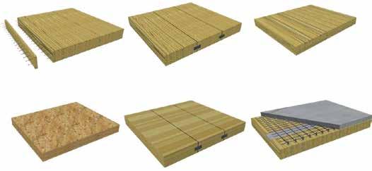
Figure 1. Mass timber panelized products.
Mass timber building systems are becoming more popular throughout North America as creative and cost-effective alternatives to concrete and steel construction. While post and beam Mass Timber: Knowing Your Options timber frame buildings have been around for centuries, new panelized products have begun to change the way we build with wood. The term ‘wood construction’ is often associated By Robert Jackson, E.I.T., Tanya with light wood frame, a tried and tested method Luthi, P.E., and Ian Boyle, P.Eng., of creating buildings from dimensional lumber Struct.Eng, P.E., S.E., and sheathing. Mass timber, however, is a fundamentally different type of construction. Light wood framed buildings are typically erected on site, while mass timber buildings are usually prefabricated as a kit-of-parts which can be erected quickly and smoothly. The intent of this article is to introduce practicing engineers to mass timber panel products Robert Jackson is a Project available in the North American marketplace Engineer at Fast+Epp Structural and to highlight some key considerations unique Engineers. He can be reached at to each. rjackson@fastepp.com. Tanya Luthi is an Associate at The Timber Advantage Fast+Epp Structural Engineers. She can be reached at tluthi@fastepp.com. There are several advantages to mass timber building systems, with the first being construction speed. On mass timber projects, it is possible Ian Boyle is a Principal at Fast+Epp to see the superstructure completed 25% faster Structural Engineers. He can be than a steel, concrete, or light wood frame counreached at iboyle@fastepp.com. terpart. Almost invariably, reducing time on site reduces construction costs. Fully coordinated shop and erection drawings can create a smooth and efficient flow on site, where small and large pre-fabricated elements can be installed within a matter of days. Additionally, mass timber project sites typically require only 10% of the number of trucks to service them when compared to a concrete alternative. As most of these projects use large, prefabricated timber panels for the decking system, the labor required on the active deck can be reduced to 25% of that of a concrete alternative. With all of these factors working together, site noise is significantly reduced thereby reducing the impact on the local community. Aside from these construction phase advantages, mass timber can be an important part of the building industry’s larger narrative about sustainability, which has evolved into a fundamental market force. Structural engineers play a significant role in shaping the built environment – from creating architecturally expressive structural designs to choosing the materials used in those design. Timber is a renewable resource and should be considered in new building designs for its low embodied energy and carbon-storing abilities. It is also a beautiful material; leaving it exposed creates an opportunity to express the structure as part of the architecture.
Common Panelized Products
Several mass timber panelized products are being used as alternatives to concrete, steel, light wood frame, and masonry buildings throughout North America and Europe. Figure 1 (left to right, and top to bottom) shows the following: • Nail-Laminated Timber (NLT) • Glued-Laminated Timber (GLT) • Cross-Laminated Timber (CLT) • Laminated Strand Lumber (LSL) • Laminated Veneer Lumber (LVL) • Timber-Concrete Composites (TCC) Nail-Laminated Timber (NLT) NLT floor, roof, and wall panels have been in use since the early 1900s. These panels are typically comprised of Spruce-Pine-Fir or Douglas Fir 2X lumber stock, stood on edge and nailed together side by side. However, any wood species could be used for the lamination stock. Plywood is used to sheathe the panels, providing in-plane stiffness and shear resistance for lateral diaphragm loads. The panels can be fabricated in a shop
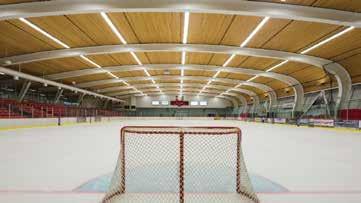
Figure 2. Mountain Equipment Co-Op Head Office. Courtesy of Ed White. Figure 3. Kin Centre Complex. Courtesy of JS Photography.
environment or they can be nailed together on-site by any reputable carpenter. Robust moisture protection during fabrication and erection is a must for NLT panels, as they are susceptible to swelling perpendicular to the grain. To mitigate these potential swelling issues, a 2X lamination should be left out every 20 feet and installed back in after the panels have acclimatized. NLT is a non-standardized one-way panel system. Standards for the base material exist in the form of typical dimensional lumber grading rules. Typical Panel Dimensions: • Thicknesses: 2.5 to 11.5 inches • Lengths: 8, 10, 12, 16 feet • Max Width (Prefabricated): 4 feet Where spans exceed 16 feet, interlocking finger-jointed lumber may be used or a staggered butt-jointed pattern may be specified. However, these longer panels tend to be less cost-effective when compared to simple span panels less than 16 feet. Additionally, a fluted profile can be created to help with acoustics and the visual appearance of the material (for example, alternating 2X4s with 2X6s in one panel). A recent project which used NLT panels in the floor and roof systems is the Mountain Equipment Co-op Head Office in Vancouver, BC, Canada (Figure 2). Panels were prefabricated in 4-foot widths and 40-foot lengths using butt-jointed laminations. Glued-Laminated Timber (GLT) GLT floor and roof panels are similar to glued-laminated timber or “glulam” beams laid on their sides, with the lamination lines running vertically. Typical species used in glulam are Spruce-Pine-Fir, Douglas Fir, Black Spruce, Alaskan Cedar, or Port Orford Cedar. Similar to NLT, plywood is used to stitch the panels together and to act as a diaphragm. The panels can be produced by any glulam supplier and shipped to site as a pre-fabricated product. Some glulam suppliers are able to provide a fluted soffit, which can help with acoustics and give a unique visual appearance. GLT panels also require robust moisture protection during erection, as they are susceptible to swelling perpendicular to the grain. One way to mitigate these potential swelling issues is to add a ¼-inch gap between each 2-foot panel, leaving room for expansion and contraction throughout the construction phase and the first few drying seasons. GLT is a standardized one-way panel system, covered by the American National Standards Institute (ANSI) A190.1-2012 Standard for Glued Laminated Timber. Typical Panel Dimensions: • Thicknesses: 3.125 to 8.5 inches • Max Lengths: 40 to 60 feet depending on supplier • Typical Spans: 15 to 30 feet • Max Widths: 2 feet, or increments of 1½ inches A recent project which used GLT panels as the secondary roof framing is the Kin Centre Complex in Prince George, BC, Canada (Figure 3). Cross-Laminated Timber (CLT) CLT panels were developed in Europe in the early 1990s and are now considered to be the most versatile and robust product for use in mass timber buildings. CLT can be used for floor, roof, and wall panels. CLT panels are comprised of 2X stock that is laminated together in an alternating crosswise pattern, similar to plywood veneers. Typical species used in CLT are SprucePine-Fir, Douglas Fir, or Black Spruce. Due to CLT’s cross laminations, the panels afford significant in-plane shear capacity and can be used as diaphragms or shear walls in building lateral systems. In these cases, panel-to-panel joints need to be carefully detailed for in-plane shear transfer. However, current U.S. building codes and material standards do not recognize the use of CLT in a lateral capacity. Special provisions may be negotiated with the authority having jurisdiction. CLT panels are currently produced to APA standards at only a few fabrication plants in North America, but many more plants exist in Europe. In-plane panel dimensions are quite stable due to the cross laminations, but the thickness of the panels remains susceptible to swelling and shrinkage. For buildings that load CLT perpendicular to grain over multiple stories, it is important to consider the shrinkage and compression that can occur through the depth of the panel as they accumulate over the height of the building. continued on next page
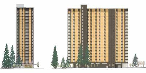
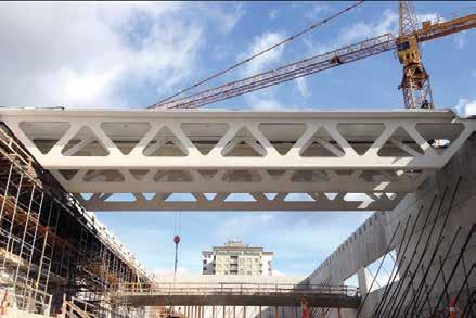
Figure 5. Guildford Recreation Centre.
CLT is a standardized product that is often used in a one-way decking capacity. However, it can also be used as a two-way bending member. In North America, the product is covered by The Engineered Wood Association’s (APA) PRG 320 Standard for Performance-Rated Cross-Laminated Timber. Typical Panel Dimensions: • Thicknesses: 4.125 inches (3-ply) to 12.375 inches (9-ply) – Many more thicknesses/layups are available depending on supplier • Max Lengths: 30 to 60 feet depending on supplier • Typical Spans: 10 to 35 feet • Max Widths: 8 and 10 feet depending on supplier. Wider panels are available from European suppliers Currently, an 18-story student residence building is being constructed as a CLT hybrid in Vancouver at the University of British Columbia (Figure 4, page 23). The building has 16 floors of two-way, 5-ply CLT panels on glulam columns. There are no beams in this building, creating a flat, point-supported surface for easy service distribution, analogous to concrete flat plate construction. Laminated Strand Lumber (LSL) LSL panels are a one-way system made from flaked wood strands that have a lengthto-thickness ratio of approximately 150. Combined with adhesive, the strands are oriented and formed into a large mat or billet and pressed together. Typically, the billets are ripped into smaller beams and rim boards for light wood frame construction, but they can also be left in their larger panel form. Aspen is used as the fiber of choice for LSL panels by most of the larger North American suppliers. Plywood is typically used to sheathe the panels, providing inplane stiffness and shear resistance for lateral diaphragm loads. Although there is some in-plane member stiffness due to the semirandom orientation of the flakes, it is not recommended nor recognized by the material standards for diaphragm applications. In-plane panel dimensions are stable due to the fiber orientation. However, as with CLT, the thickness of the panels remains susceptible to swelling and shrinkage. Typical Panel Dimensions: • Thicknesses: 1.5 and 3.5 inches • Max Length: 64 feet • Typical Spans: 10 to 20 feet • Max Width: 4 feet Although mass timber products are often used for floor and roof panels, the larger scale of LSL billets offers unique opportunities to machine large structural components out of a single piece, minimizing connections. The recently completed Guildford Recreation Centre in Surrey, BC, used machined LSL billets to create the webs in prefabricated roof trusses spanning 90 feet (Figure 5). Laminated Veneer Lumber (LVL) LVL panels are a one-way system comprised of glued plywood veneers stacked in parallel, essentially a thicker, single-direction plywood. Typically, the billets are ripped into smaller beams for light wood frame construction but, similar to LSL, they can also be left in their larger panel form. Douglas Fir is used as the veneer in LVL panels. Many suppliers in North America can supply LVL beams and billets. Plywood is typically used to sheathe the panels, providing in-plane stiffness for lateral diaphragm loads. It is not recommended to use LVL panels in diaphragm applications, as the product is not cross-laminated. Similar to LSL, the in-plane panel dimensions are stable; however, the thickness of the panels remains susceptible to swelling and shrinkage. Some Canadian and European suppliers also laminate LVL beams on edge into panels, which exposes the end and edge grain of the veneers rather than the face grain in a typical exposed LVL billet. This technique gives a clean, visual aesthetic and can be used to produce a larger range of thicknesses. Typical Panel Dimensions – LVL Billet: • Thicknesses: 1.75 and 3.5 inches • Max Length: 66 feet • Typical Spans: 10 to 20 feet • Max Width: 4 feet Typical Panel Dimensions – Secondary LVL: • Thicknesses: 3.125 to 11.5 inches • Max Length: 60 feet • Typical Spans: 10 to 40 feet • Max Width: 4 feet Timber-Concrete Composites (TCC) Timber-concrete composite panels consist of a thicker layer of concrete on the top side and a mass timber panel on the bottom side. The concrete acts as a compression element while the timber acts as the tension element, giving flexural stiffness. There are several ways to engineer the connection between the concrete and timber, generating the required shear flow. They range from glued-in perforated steel plates to fully threaded screws installed at an angle. TCC floor systems are very efficient and can achieve high span-to-depth ratios. The depth of the concrete topping also allows for electrical conduits and in-floor heating lines to be hidden inside the floor system. Any of the mass timber panels previously mentioned can work as the tension lamination in a TCC floor system. Typically, the concrete is cast on-site directly on top of the timber panels, connecting them together. However, precast versions of the concrete compression element are possible by installing proprietary screw sleeves within the concrete. Additionally, timber-concrete composite T-beams are possible with wood beams rather than a wood panel.
Building Codes + Material Standards
All of the products listed above are covered in the International Building Code (IBC 2015). Projects falling into construction types III, IV (Heavy Timber), and V are
the likely candidates for a mass timber alternative. Depending on the occupancy classification, the permitted height for these construction types can be up to 85 feet. Although Type I and II construction are limited to non-combustible materials, mass timber roofs are permitted. Additionally, there are taller mass timber projects in New York and Oregon, which are negotiating jurisdictional approvals with the local building authorities. All of the products are covered in the National Design Specification (NDS 2015) for timber design. NLT, GLT, and CLT can be designed in accordance with Chapters 4, 5, and 10 respectively. LSL, LVL, and Secondary LVL should be designed in accordance with Chapter 8. Reference values are not provided for LSL or LVL in NDS 2015, as they are unique to each supplier’s APA product reports. It is possible to calculate individual CLT panel capacities with the Kreuzinger shear analogy method. However, NDS 2015 also requires that the resistance values be taken from the individual supplier’s APA product reports and then further modified with the Chapter 10 factors. Under current U.S. codes and material standards, all of the mass timber panel products require plywood sheathing for in-plane diaphragm stiffness and shear resistance. The use of CLT without plywood is indeed a viable solution but must be negotiated with the authority having jurisdiction. Plywood diaphragms on mass timber panels can be considered as “fully blocked” when detailing with the NDS 2015 Special Design Provisions for Wind and Seismic (SDPWS).

Conclusion
A broad variety of mass timber products is available in today’s market, suitable for many project types in the North American building industry. Knowing your product options is critical when starting to design a mass timber building system. With this introductory information, engineers should be able to make informed design decisions regarding each product. Mass timber construction has been in use in Europe for decades, with great success. This style of construction continues to grow in popularity in North America. As engineers, we have the opportunity to play a significant role in shaping and promoting this type of construction. With mass timber, architecturally expressive and sustainable structures can be created, adding value to your client’s project.▪
MAKING NEW AND EXISTING STRUCTURES STRONGER AND LAST LONGER
INNOVATIVE PRODUCTS
STRUCTURAL TECHNOLOGIES’ V-Wrap™ FRP is a lightweight, high-strength, code approved composite system for concrete and masonry structures and structural elements. These lightweight, high-strength materials are used to restore and upgrade load-carrying capacity.
PERFORMANCE
• Long-term durability • ICC-ES approved • UL-approved fire-resistant finishes available
FLEXIBLE AND EFFICIENT
• Utilized on a variety of structural elements • Ideal for complex geometries • Result in faster schedule and cost savings
RELIABLE SUPPORT
STRUCTURAL TECHNOLOGIES combines comprehensive, no-cost, technical support from industry experts with extensive and relevant structural engineering experience, including expertise in seismic applications.
EXPERTISE
• Product selection • Specifications • Preliminary design • Construction budgets
Our Strengthening Solution Builders ensure V-Wrap™ systems are engineered to meet a project’s specific requirements with components that optimize application performance. Quality you can trust from a rock solid team you can rely on.
www.structuraltechnologies.com | 410-859-6539
RAISING THE BAR
By Patrick Ragan, S.E., and James Swanson, S.E., P.E.
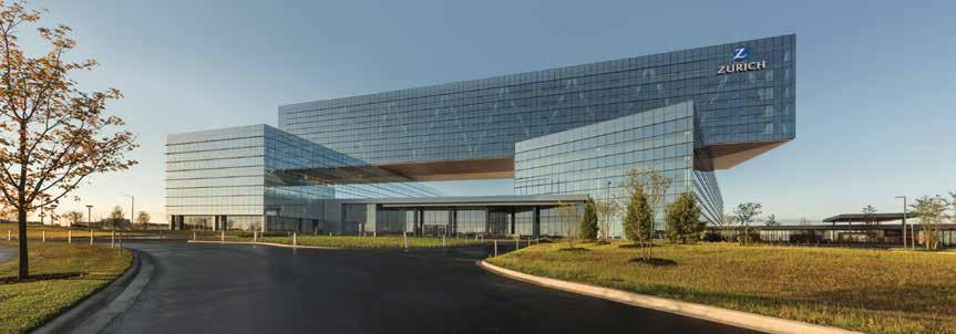
Courtesy of James Steinkamp Photography.
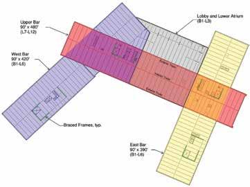
The 783,800-square-foot Zurich North America Headquarters is the largest build-to-suit office project completed in the Chicago area in the last 15 years, but this striking addition to the I-90 corridor in Schaumburg is not just notable for its size. The unique building form is comprised of the three long rectangular bars shown in Figure 1. The east and west lower bars rise six stories from the ground, while the five-story upper bar sits on top of – and spans between – the two lower bars.
A Building and a Bridge
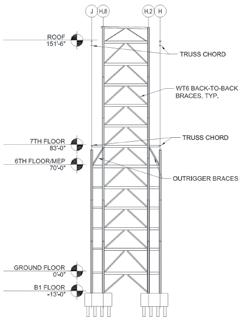
The dramatic 180-foot main span and the two 60-foot cantilever spans on each end are made possible by two steel trusses at the exterior faces of the upper bar and a third truss centrally located in the interior. Usually, a requirement to transfer five levels of office loading over such long spans would be an arduous task associated with a significant cost premium. In this case, however, loads from the upper bar are not carried by a one-story or two-story transfer truss. Instead, the main structure of the entire upper bar is a truss. By replacing vertical columns with truss diagonals throughout the entire five-story upper bar office space, the full 68-foot height of the space becomes structural depth for the truss, allowing chord axial forces to be minimized. Additional efficiency is achieved by making the truss continuous over its supports, and ideally proportioning the cantilever spans to balance forces and deflections in the main span. These effects further reduce chord axial forces and result in deflections which are approximately equal at the main span and the cantilevers. Although the depth and continuity of the trusses make them inherently stiff, and therefore not prone to large deflections, the trusses were fabricated and erected with slight cambers to mitigate concerns about floor levelness. By super-elevating initial panel point elevations by up to one inch, the initial truss deflection due to dead load was effectively eliminated. Meanwhile, live load deflections are less than ¾-inch at both the main span and the cantilevers.
Truss Design
The design of the truss chords was governed by the axial truss forces acting in combination with significant bending moments, since the chords also act as 60-foot continuous W36 steel girders supporting the conventional 45-foot composite steel framing. A series of large truss chord penetrations (40 inches wide x 22 inches high) were carefully coordinated to allow mechanical services to fit within the standard 13-foot-six-inch floor-tofloor heights without compromising the ceiling height. While coordination of the deep truss chords with mechanical services was a challenge, coordination of the truss diagonals with the
Figure 1. Plan diagram.
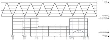
Figure 2. Typical main truss elevation.
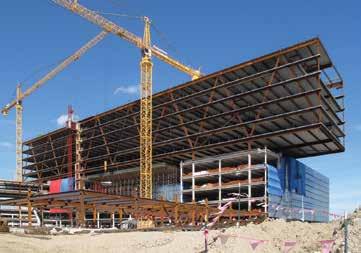
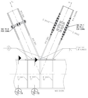
Figure 4. Typical truss diagonal-to-chord node. The force in the compression diagonal (left) is transferred primarily through bearing. Courtesy of Ruby Associates. Figure 5. Typical elevation of primary north-south-braced frames.
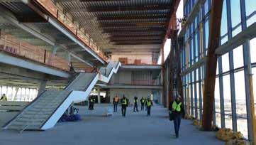
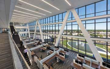
Figure 6. Upper bar atrium with long-span steel staircase connecting levels 9, 10, and 11. Courtesy of Goettsch Partners.
interior office space was less so. As the centerpiece to the most iconic component of the project, the trusses are featured and celebrated by the architecture rather than hidden behind partition walls. Early in the design phase, the design team worked closely with the contractor’s connection engineer to develop economical splices and compact connections at the truss nodes. The typical truss diagonalto-chord node (Figure 4) was shop-welded and delivered to the site in one piece with the chord, with bolted diagonal splices accommodated on both sides of the node. Where possible, bolt quantities were reduced by taking advantage of bearing, such as in compression diagonals which were not subject to load reversals.
Braced Frames
With a roof height of 152 feet, the building will not be confused with the tallest high-rise office buildings found in downtown Chicago. Still, the 480-foot wide wind sail of the upper bar, in combination with the Exposure C wind loads blowing off the expressway from the south, creates substantial overturning forces that required creativity in the layout of the two braced frame cores which stabilize each end of the upper bar. The typical elevation of the primary north-south braced frames is shown in Figure 5. It was critical to take advantage of the large gravity loads present in the columns supporting the main trusses to minimize foundation tensions. However, the trusses are laid out on a 45-foot module, while the extent of the braced frames was limited to the 29-foot-8-inch width of the elevator core. Outrigger braces were provided directly beneath the upper bar at the Level 6 mechanical level at each of the four brace lines to engage the truss support columns and their beneficial gravity loads. In addition to reducing the uplift forces, the extra depth of the structural system, combined with the high axial stiffness of the large truss support columns, ensured that lateral drifts could be controlled with a minimal steel weight premium beyond what was required for strength.
Open Spaces
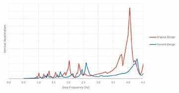
Four large atrium spaces give the interior a dramatic feel befitting the project, and a series of feature staircases connect the various levels served by the atriums. The longest, shown in Figure 6, spans 40 feet between Level 9 and a 17-foot cantilever landing at Level 10, and another 50 feet between the Level 10 landing and Level 11. Given the susceptibility of long-span staircases to vibration, a series of dynamic analyses were undertaken to predict the vertical accelerations at mid-span of the stair under the worst case of a rapidly descending individual. Since the dynamic response of a long-span stair is a highly nonlinear problem, it is possible for a moderate increase in stiffness to result in dramatically improved behavior. In this case, the initial stair design based on strength and deflection was stiffened by optimizing the steel stringer profile, with a 3-inch increase in depth and a modest increase in steel weight. This reduced the estimated stair accelerations under the controlling case by more than a factor of 3 (Figure 8, page 28) compared to the initial design.
Challenging Soil Conditions
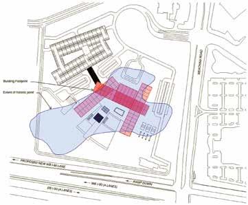
Ground conditions at the site consisted of significant regions of soft fill and organic clays, particularly on the south end of the site where, as shown in Figure 10 (page 28), a large pond had previously existed. To mitigate differential settlements during and after construction, an innovative “preloading” program was undertaken in which approximately 20 feet of soil from the adjacent parking garage excavation was
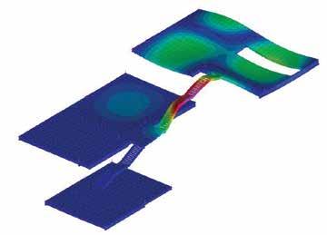
Figure 7. Atrium staircase primary mode of vibration. Figure 8. Vertical acceleration at mid-span of staircase versus step frequency of a descending individual.
Figure 9. View from level 10 of the upper bar atrium. Courtesy of James Steinkamp Photography.
Figure 10. The extent of the old pond encompasses the majority of the building footprint.
piled on top of the entire building area of the site. Over the course of 60 days, the weight of the additional fill, in conjunction with 20 to 35-foot long vertical “wick drains” arranged in a 5-foot triangular grid pattern, accelerated the consolidation and settlement of the soft organic material. Upwards of three feet of settlement was observed during the preloading phase; additional settlement after construction is anticipated to be limited to approximately one inch. Had the preloading program not been implemented, a significant portion of the settlement would have occurred after construction. Also, a suspended slab system would have been required in the basement rather than the traditional slab-on-grade which was ultimately used. Moreover, the continuous flight auger (CFA) piles used for the deep foundation system would have been subjected to “down-drag” forces – essentially negative skin friction – as the surrounding soils consolidated. The resulting reduced capacities would have required significantly more piles and associated expense. Notably, the preloading and drainage program also mitigated the susceptibility of the soils to liquefaction under seismic loads, allowing the seismic site classification to be reduced from F to D. This corresponds to a considerable reduction in seismic forces and detailing requirements, and eliminated the need to perform a site-specific seismic response analysis.
Conclusion
A careful integration of structure – in particular, the three structural steel trusses of the suspended upper bar – allowed this iconic piece of architecture to stand apart from its peers in the suburban office building landscape. After opening in October 2016 to rave reviews from occupants and critics alike, it is clear that the Zurich North America Headquarters has quite literally raised the bar for the suburban office building.▪
Project Team
Owner: SFG Schaumburg 1, LLC Structural Engineer: Halvorson and Partners, a WSP | Parsons Brinckerhoff Company Occupant: Zurich North America Developer/Design-Builder: Clayco Architect: Goettsch Partners Geotechnical Engineer: GEI Consultants Patrick Ragan, S.E. (pragan@hpse.com) is a Senior Engineer with Halvorson and Partners, a WSP | Parsons Brinckerhoff Company in Chicago. James Swanson, S.E., P.E. (jswanson@hpse.com) is a Senior Vice President with Halvorson and Partners.
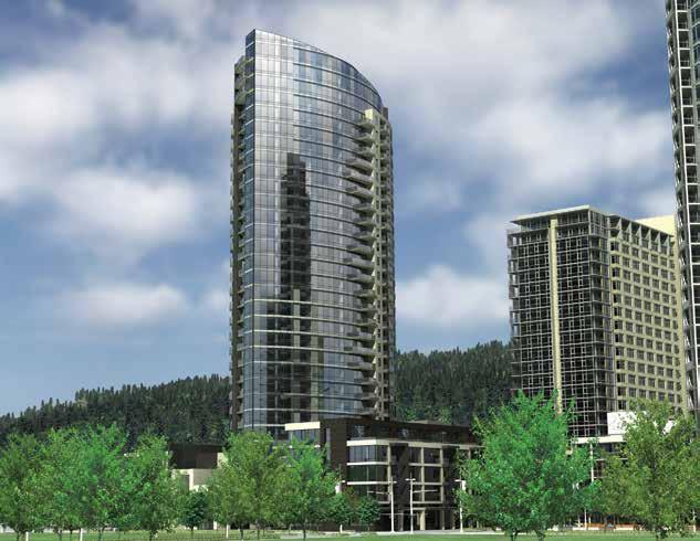
The Wharf 525 Water Washington, DC
By Bill Wilde and Joe Wilkum

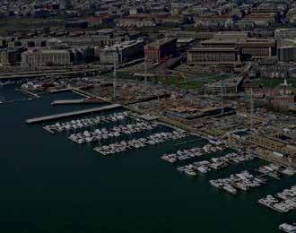
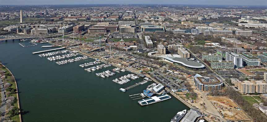
The Wharf development is transforming Washington DC’s storied Southwest quadrant by creating a mile-long waterfront neighborhood that includes retail, residential, hospitality, o ces and cultural complexes as well as a public park and piers. 525 Water is a 107-unit condominium building in Washington, D.C. and the rst residential project to be constructed in e Wharf. e 525 Water project is located in the lower right area of the development shown in Figure 1. Featuring views of the Potomac River and fronting a new 3.5-acre Waterfront Park (Figure 2), these new condominiums extend ve stories above grade and contain over 105,000 square feet. e building is primarily a square shape, with a curved southern exposure matching the radius of the streetscape (Figure 3). Its courtyard o ers landscaped scenery and natural lighting for residents of the interior units. Other amenities include a club room, private rooftop, balconies, green roof, and a two-story garage substructure. Final punch list items were completed in July 2016 with a construction cost of $30 M. e project consisted primarily of load-bearing cold-formed steel framing (Figure 4). e load-bearing wall panels support concrete over Hambro joists for levels three and above. Over 9,000 linear feet of wall framing containing complex curves and angles was prefabricated o -site by FrameCo, Inc. On May 5, 2015, the rst of over 1,040 panels was placed on the second oor. In just three months, the structure was topped out with its nal pour at the roof. Although masonry elevator and stair shafts were included in the building design, cold-formed X-braces stabilize the building above the second level. e garage and rst-level structure were constructed with concrete columns supporting reinforced two-way concrete slabs. e rst story exterior wall is in ll curtain wall fabricated with cold-formed steel framing and de ection track at the top of the wall. ese curtain walls were installed after much of the second story was already in place e exterior facade is composed primarily of brick, metal panels, and glass. In some locations, the cold-formed steel framing was required to support the vertical as well as the lateral loads imposed by the brick veneer. A prominent feature of the exterior is the tower occurring at the building’s southwest corner, (Figure 2) which contains oor-to-ceiling glazing supported by miscellaneous cold-formed shapes and structural steel. e bene t of cold-formed prefabricated panels on this project is best exempli ed by the beam pockets that were required to achieve a positive load path (Figure 5). With over 100 steel beams at the fth level, Excel Engineering, Inc coordinated beam depth, width, and bearing locations so that appropriately sized cold-formed posts
Figure 1. Overview of the project area.

Figure 2. Rendering of e Wharf area.
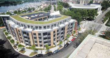
Figure 3. 525 Water at the Wharf.
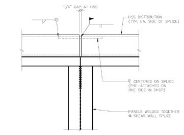
could be provided. e posts were capable of supporting each beam while still allowing adequate space for the eld crew to make their connections. is avoided costly delays associated with traditional ironwork. Adding to the complexity, more than 550 MEP (mechanical, electrical and plumbing services) sleeves penetrated each level. Excel coordinated every stud location to avoid interference and enable a much faster installation of the wall panels. Shear walls are an integral part of many projects, and this project was no di erent. Aligning the shear wall posts oor-to- oor, in particular through concrete, is di cult and required Excel to work with FrameCo on a creative solution. Taller cold-formed shear wall posts with cap plates were designed and supplied within each panel (Figure 6). e panel above contained slots in its bottom track at
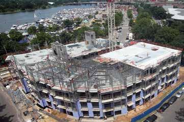
Figure 4. Typical story framing.
these posts, enabling the field crew to properly align the shear wall post and directly weld each assembly together. Due to the nature of the project, some shear walls were not able to be shipped full-length. Therefore, Excel created an overlap detail (Figure 7) to maintain continuity across the splice between shear wall panels. This involved welding a plate that extended past the end of one panel so it could be fastened to the adjacent panel once set in the field. Due to an aggressive construction schedule, Excel Engineering, Inc. developed an innovative process to communicate new information among team members quickly. Requests for Information (RFIs) were submitted well before the engineering was completed, and a level of importance was assigned to each request so the design team could address time-sensitive issues first. Excel also provided a level of accelerated service by handling complex aspects directly with the project design team. This coordination process alerted the design team of potential issues, allowing them to be resolved before they could create delays. For instance, in-depth coordination with the stair fabricator was required for beam design at the fifth-level stair openings. By anticipating the need and addressing it upfront, Excel was able to produce accurate wall panel elevation drawings quickly. Combining attention to detail with innovative design, Excel and FrameCo demonstrated that prefabricated cold-formed steel systems can work perfectly as the primary structure for any mid-rise building. 525 Water was recently recognized by the ColdFormed Steel Engineers Institute with a 2016 CFSEI Design Excellence Award for its’ innovative use of cold-formed steel.▪
Bill Wilde is a cold-formed load bearing and wall panel specialist in the industry. He may be reached at bill.w@excelengineer.com. Joe Wilkum is a Project Manager at Excel. He is experienced with curtainwall design, although load bearing design is his specialty. He may be reached at joe.w@excelengineer.com.
Project Team
Owner: RWP, LLC Engineer of Record for Structural Work: Ehlert Bryan Architect of Record: SK&I Architectural Design Group, LLC Cold-Formed Steel Specialty Engineer: Excel Engineering, Inc. Cold-Formed Steel Specialty Contractor: FrameCo, Inc. General Contractor: Balfour Beatty Construction
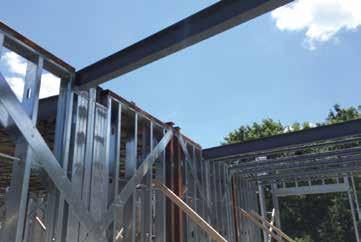
Figure 5. Typical framing with beam pockets.
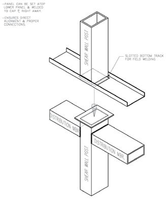
Figure 6. Typical shear wall post cap plate detail.