30 minute read
Professional Issues
issues affecting the structural engineering profession Passing the New Structural Exam–You Too Can Do It after Turning 40 by Thomas A. Grogan, Jr., P.E., S.E., which appeared in the September 2011 issue of STRUCTURE®, detailed an excellent strategy for preparing to pass the new SE exam. This article provides further information on the SE exam and some of the tools available to help you study. These tools can also be used to prepare for the PE Civil: Structural exam.
The SE Exam
Beginning in April 2011, the SE exam was reorganized into a 16-hour exam spread over a Friday and Saturday. The Friday component focuses on Vertical Forces, and Saturday focuses on Lateral Forces. Both days are broken into 4-hour sections, with the morning covering breadth problems in a multiple choice format and the afternoon containing a choice of essay (work out) problems. Examinees must choose between either Buildings or Bridges for both of Structural Exam Study Aids the afternoon modules, and the two cannot be combined. In this way a single area of practice The Key to Your Success (buildings or bridges) is evaluated in depth. Each of the morning breadth modules contain By Christine A. Subasic, P.E., a total of 40 multiple choice questions that must LEED AP be completed in a 4 hour time period. This provides an average of 6 minutes to complete each problem. It is important to answer all of these questions, even if you have to guess, as unanswered questions count as wrong answers. The morning breadth problems may include both building and bridge problems. Each of the afternoon depth modules requires examinees to complete 3 or 4 problems in either the area of buildings or bridges. The amount of time available for each problem depends on the module chosen. The breakdown of the depth problems is shown in the Table.
The PE Exam
The PE Civil: Structural exam follows a similar format but is only an 8-hour exam. It is composed of a 4-hour morning breadth module and a 4-hour afternoon depth module. However, for the PE Civil: Structural exam, both modules are multiple-choice format, with an average of 6 minutes to complete each problem. In addition, the Structural depth module can include both building and bridge problems.
Choose Your Study Aids
So what is the best way to prepare? There are many types of study aids available to choose from. A brief (unscientific) survey of some recent examinees indicated that sample multiple-choice problems and solutions was the most helpful type of study aid, followed by other solved problems. Several publishers produce study aids with multiple-choice problems, including NCEES,
Christine A. Subasic, P.E., LEED AP is a consulting architectural engineer in Raleigh, NC, specializing in sustainable design and masonry. She is also the author of “SixMinute Solutions for the Civil PE Exam Structural Problems” and “Six-Minute Solutions for the Structural I PE Exam Problems,” and co-author of “The Masonry Designers’ Guide.” She can be reached at CSubasicPE@aol.com.
SE Exam Afternoon Depth Problems.
Vertical Depth Component Lateral Depth Component
Buildings Module Four 1-hour problems in each of Four 1-hour problems in each of the following areas: the following areas: • Steel structure • Steel structure • Concrete structure • Concrete structure • Wood structure • Wood and/or masonry structure • Masonry structure • General analysis (e.g., existing At least one problem includes a structures, secondary structures, multistory building, and at least nonbuilding structures, and/or one problem includes a foundation. computer verification) At least two problems include seismic content at Seismic Design Category D and above, and at least one problem includes wind content of at least 110 mph. Problems may include a multistory building and may include a foundation.
Bridges Module Two 1-hour problems and one 2-hour problem in the following areas: • Concrete superstructure (1 hour) • Other elements of bridges (e.g., culverts, abutments, retaining walls) (1 hour) • Steel superstructure (2 hours) Two 1-hour problems and one 2-hour problem, in the following areas: • Columns (1 hour) • Footings (1 hour) • General analysis (i.e., seismic and/or wind) (2 hours)
Professional Publications Inc., and others. Th e study aids identifi ed as most helpful by those surveyed are described below, but are in no way the only options available. One popular option is the Six-Minute Solutions series published by Professional Publications Inc. Th is series gets its name from the average of 6 minutes that you have for each of the multiple-choice questions on the exam. Th ese books contain 80 to 100 multiple choice questions like those encountered on the exam and detailed, step-by-step solutions. Th e problems cover most of the topics included in the NCEES exam specifi cations, and wrong answers are based on mistakes that are easy to make. Another option is the NCEES sample exam study materials, published for both the SE exam and the PE exams. Th ese guides contain sample exam questions and solutions in the exact format they appear on the actual exams. Kaplan also publishes a series of review books, sample problems, as well as online tools to aid in studying for the SE and PE exams. Th ough not mentioned by the survey respondents, there are a number of other online resources available, which can easily be found with an online search for “PE exam study”. Options include webinars as well as self-paced online study aids. In many cases, you have a choice of a complete exam preparation package covering all topics likely to be found on the exam, or choosing only select topics that you feel you need the most review. For example, many state and national engineering associations off er webinars on specifi c topics covered in the PE/SE Exams. Th ere are several websites that off er online study aids for specifi c subject areas.
ADVERTISEMENT - For Advertiser Information, visit www.STRUCTUREmag.org
Practice, Practice, Practice and Plan for the Test
Th e key to successful preparation is practice solving problems – lots of them. Or as one survey respondant said, “Work as many practice problems as you can.” Recent examinees also had the following advice to off er: “Manage your time during the exam! You must bring a watch to manage time. Time seems to go by very quickly during the exam.” “Tab out your books so you can quickly fi nd the appropriate information. When you think you have worked enough sample questions, work more. Create a binder with useful reference material and organize it by subject (e.g. concrete, wood, steel).” “Cover all the topics in proportion to the expected questions on the test; mark your references for quick access.” With so many choices available, everyone should be able to fi nd something that works for them. Th e secret to success is doing the work, regardless of which tools you choose. Allow yourself plenty of time to prepare. It’s real work, but the benefi ts are real as well. Good Luck!▪
Preserve Your Project Before It’s Even Built.
Galvanizing is Thinking Big Picture.
Hot-dip galvanizing with AZZ Galvanizing Services is the best way to ensure that your project will stand the test of time, saving money in costly maintenance repairs later. And since using eco-friendly zinc is less expensive than other corrosion barriers, the cost savings begin before the construction does — and will extend the life of the structure. Save money now and in the big picture.
azzgalvanizing.com
We Protect More Than Steel.
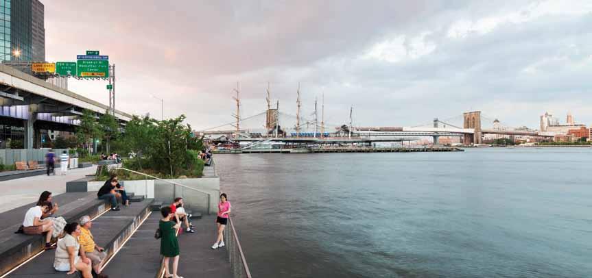
A look at the completed waterfront project.
New York Waterfronts
Structural Engineering Challenges
By Cliff McMillan, P.E., C.Eng
With 500 miles of shoreline, New York’s waterfront is the largest of any city in the world. After decades of neglect, the waterfront has again become a place of intense interest for government and civic organizations. With the 1992 New York City Comprehensive Waterfront Plan and 2001’s Vision 2020: New York City Comprehensive Waterfront Plan, the city government took stock of the needs and opportunities of the waterfront and laid out plans to transform it for the benefit of all New Yorkers. Arup has been involved in this process for over a decade, with six discrete waterfront projects covering almost nine miles in total, including Hudson River Park, the East River Waterfront, Teardrop Park, Pier A in Manhattan, and Hunter’s Point in Queens. Structural engineering plays a vital role in waterfront projects in supporting clients and design teams to achieve durable and cost-effective results. Construction efficiency, longevity and cost-effectiveness all rely upon intelligent structural solutions that take into account a project’s full lifecycle. Structural elements such as piers and seawalls often consume a large proportion of a project’s initial budget, and repairs and maintenance can lead to significant costs down the road.
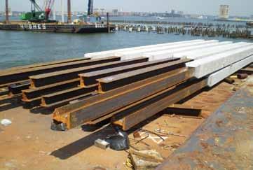
Figure 1: Hybrid steel concrete pile. The design adopted a hybrid steel and concrete pile to manage the poor soils above the rock. Courtesy of Hudson River Park Trust. For these reasons, close attention is paid to structural design on all waterfront work, with particular challenges arising in relation to longevity, pier design, materials selection, and flooding.
Longevity
The harsh marine environment of Manhattan’s waterfronts – with their damp, salty atmosphere, intense solar exposure, constant cycles of wetting and drying due to splashing and tide range, and damage caused by skateboarders and vandals – can lead to the untimely deterioration of even the hardiest materials. These factors are considered at a particular site to develop a design that avoids the need for maintenance as much as possible. In targeting a 50-year lifespan or more for all park structures and permanent exterior elements, sustainable, durable materials matched to the particular demands of their setting are all considered.
Pier Design
Meeting the goal of a 50-year lifespan represents a particular challenge for pier design due to the forces they have to resist and the extent of their exposure to corrosive elements. Piers have to be designed for a wide range of structural loads, including 1) self-weight, 2) dead loads due to the make-up to achieve surface treatments and soil for planting and trees, 3) live loads arising from the planned activities on the pier, and 4) lateral loads from wind, seismic effects, currents, ice and possible vessel mooring forces and impacts. All these have to be considered in relation to the particular circumstances and to provide flexibility for possible future changes – for instance, the type of vessels likely to be moored in the future, or the depth of soil needed to accommodate possible tree layouts. Geological conditions along New York’s shoreline and rivers can be variable over short distances and are often unfavorable for foundations, thereby presenting major challenges. New York City river silts, sands and clays vary greatly in composition and depth. At some points around Manhattan, rock begins at riverbed level; at others, such as several of the Hudson River Park piers, piles had to be driven to over 300 feet below the surface. Seismic considerations then become a
significant factor. Providing sufficient lateral support to the piles, and the depth of water and poor material below the pier deck before such lateral support is achieved, can become a dominant factor in the design. At Hudson River Park, the very long piles founded on rock at up to 350 feet deep and the poor soils above the rock, presented a particular challenge. The design adopted used a hybrid steel and concrete pile. For the upper approximately 70 feet – through the water and weakest soils – pile stiffness, bending strength and corrosion resistance are most critical. A high quality 24-inch-square precast, prestressed concrete pile section was used. Cast in a controlled environment and tensioned to minimize cracks provides high strength and durability. Below that, corrosion and bending resistance are not a critical issue, and the loads in the pile are primarily axial. There, a steel HP section, up to more than 200 feet long, transfers the load to the rock. The connections between the concrete and the steel section, and between successive steel sections, were designed to ensure simple construction in the field (Figure 1). This hybrid pile was less expensive than an all-concrete pile; by minimizing the concrete, its weight was reduced substantially, which was beneficial during the lifting and splicing process, and costs were saved. It was felt that the high-quality concrete section in the vulnerable upper zone provided better corrosion resistance and durability than corrosion-protected structural steel. To provide further protection, the concrete specification was designed to prevent reinforcement corrosion, usually caused by chloride ion inward migration. A concrete blend suited to preventing this phenomenon was selected, and epoxy-coated rebar was used for all reinforced concrete structures, as epoxy stops moisture and chlorides from corroding the steel. Another issue with pier design is the form of superstructure construction and how to accommodate the form needed by the landscape design, program design and also the often extensive utilities and services required on the pier – water, electricity, gas, fire and waste disposal. Because of the constraints of over-water construction, the most cost-effective structure usually employs a rectangular pile grid and a flat or uniformly sloping deck. This facilitates the use of precast concrete pile caps and longitudinal beams with precast concrete slabs spanning between the pile caps. The build-up above the pier deck to create the surface shaping, necessary for the landscape design program and to accommodate services and utilities, can then be achieved in a number of ways. To reduce dead loads, styrene foam and lightweight fill were used on the Hudson River Park pier to create the shaping. The services were accommodated within the void above the structural deck (Figure 2).
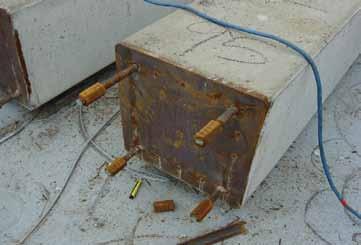
Figure 2: Plate at the bottom of the concrete which connects to the steel section. The connections use a simple detail to facilitate construction in the field. Courtesy of Hudson River Park Trust. Figure 3: The installation of new concrete pile caps over the new precast concrete piles. Pile caps are elevated to avoid contact with river water. Courtesy of Hudson River Park Trust.
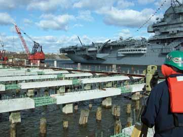
To drain the space above the deck, and avoid saturation and damage to plants and utilities when the tide rises, non-return valves were provided at the underside of the structure to allow any water to drain out when the tide is low but to prevent inflow when the tide is high. On Pier 15 at East River Waterfront, a utility trench runs the length of the pier within the structure to accommodate the utilities that serve the buildings out on the pier and provide maintenance access. For this two-level pier, the structural columns supporting the upper deck are located to coincide with the piles below. These designs minimize interaction between the structure and the harsh water environment to the fullest extent possible. Pile caps, for example, are elevated so as to typically avoid contact with river water (Figure 3). Often new piers are built over or among the remains of the timber piles from previous piers. This means careful mapping of the old piles to minimize conflicts when the new piles are driven. Some of the old piles can be retained to provide a visual connection to the history of the park, as well as a habitat for fish, wildfowl, and other marine life. Sometimes new over-water esplanade areas are constructed on existing but deteriorated platforms. This requires careful study of the existing conditions, and the load capacity and state of deterioration of the existing piles and structure. Often strengthening of the existing structures becomes necessary.
Materials Selection
A key objective throughout the design was to ensure low maintenance and operational costs, partly through the choice of sustainable, durable materials. Common structural and non-structural elements that require consideration are: railings, paving, lighting, benches and other outside furniture. For instance, for the extensive length of railing on the Hudson River Park pier, Grade 317 stainless steel was selected to improve corrosion resistance. Even with this material, a coating of Adsil, a commercial coating product, proved necessary to minimize “tea-staining” in the harsh, salty environment. FieldTurf grass, a synthetic grass that is designed to mimic real grass, was selected to provide a maintenancefree surface for sports fields and picnic areas on piers. For timber rails and benches, selected tropical hardwood Ipe, farmed from forests
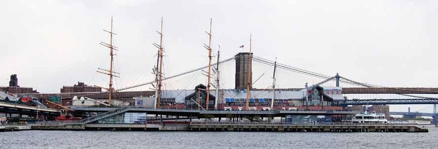
Figure 5: East River Pier 15 deck had to be raised to the flood elevation to accommodate the small pavilions below the code requirement of the FEMA flood elevation. Courtesy of Arup.
certified to meet sustainability requirements, were specified. For the esplanade, granite and blue stone paving were selected. Where structural steel is used for marine structures, such as pier piles or floating structures, several methods of corrosion prevention were considered. Some piles were coated with glass flake epoxy. Others were covered in fiberglass jackets and epoxy. Cathodic protection has been used for protection on projects, but this has limitations in the splash zone, and is considered by some clients to be a maintenance burden because of the need for an electric current (Figure 4).
Flooding Resilience
An important factor in the design of the piers and esplanades is the flood elevation under the 100-year Federal Emergency Management Agency (FEMA) extreme flood conditions. This would involve overtopping of existing piers and esplanades around Manhattan, sometimes to the extent of 3 feet. The typical finished esplanade elevation is fixed in relation to the historic bulkhead elevations, as well as the finished grades utilized in the reconstruction of the roads such as Route 9A which runs along the Hudson River waterfront. As a result, the esplanade elevation at Hudson River Park and East River Waterfront is set generally around three feet below the FEMA 100-year flood level. By this approach, buildings on the esplanade or piers would generally be subject to occasional flooding in extreme circumstances.
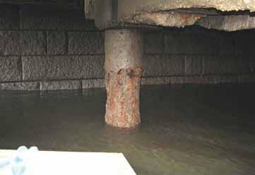
Figure 4: Corrosion of steel piles in intertidal splash zone, without protection. (Instead of showing cathodic protection, this photo shows what happens when the pile is not protected.) Courtesy of Hudson River Park Trust. This means that the park buildings would either have to be raised to meet the code stipulated FEMA requirement, or be designed to withstand flooding and be “drip dry” after flooding. All electrical and mechanical equipment and critical services are elevated to above the 100-year flood level. For the East River Waterfront, it became necessary to obtain a variance through the Board of Standards and Appeals in order to build small pavilions below the code requirement of the FEMA flood elevation. This variation was granted specifically for the unusual headroom constraints under the existing Franklin Delano Roosevelt Drive. The elevation of the East River Pier 15 deck had to be raised to the flood elevation to accommodate the small buildings (Figure 5).
Creating a Legacy for New York City
Until the 90s the city of New York turned its back on its waterfront. Hudson River Park, East River Waterfront, and other recent developments mark a dramatic shift in attitude towards the water and waterfront amenity. Mayor Michael Bloomberg and his administration’s strong commitment to the issue, along with public demand for waterfront access, and the extent of the shoreline, present countless opportunities for the city. While the 500 miles of New York City waterfront pose a tremendous opportunity, they also create a tremendous design challenge. The waterfront is not an infinite resource; it is often narrow and fragmented and is subject to competing interests such as marine habitat preservation, public demand for amenity, and commercial demand for prime locations. They also present a range of engineering challenges, including dealing with an aggressive, salt-laden physical environment that makes material selection critical for providing durability, resisting aging and deterioration, and satisfying regulatory and permitting requirements. The waterfronts referred to above have responded to these special challenges with unique solutions that demonstrate success in improving quality of life and also in expanding our expectations of what waterfront spaces can become.▪ Cliff McMillan, P.E., C.Eng, is a Principal in Arup’s NewYork office. He has been deeply involved with several Manhattan waterfront projects over the past 11 years, including leading Arup’s multi-disciplinary design coordination and management services since 2001 on the entire five miles of Hudson River Park and on the design of East River Waterfront. He may be reached at Cliff.McMillan@arup.com.
Lessons Learned from the Joplin Tornado
By Curtis Geise, P.E., S.E.
Non-residential building remains standing despite major damage.
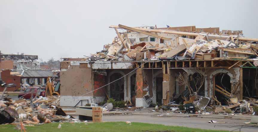
The Joplin Tornado of May 2011 was one of the most destructive natural disasters ever to hit the state of Missouri. There were more than 160 deaths, 1,100 injuries and $3 billion in damages. The physical and psychological impact will not soon be forgotten. In consideration of the magnitude of devastation to the built environment, the Structural Engineers Association of Kansas & Missouri (SEAKM), a Member Organization of NCSEA, formed a committee to investigate the performance of structures affected by the tornado, whether directly or indirectly. This article offers some of the committee’s observations and recommendations, which are based on site reconnaissance and other information. The committee’s full report will be posted on SEAKM’s website (www.seakm.com). In general, structures designed in accordance with building codes, such as those published by the International Code Council (ICC), are not required to resist tornado wind effects. Tornado wind speeds vary greatly and may exceed 200 mph, as was the case with the Joplin Tornado. The International Building Code (IBC) 2006 establishes a baseline of 90 mph as the basic wind speed for this area of the country. Observations of wood structures indicated the main area of vulnerability is maintaining a strong load path through connections. Overall, the wood structures reviewed were of an older generation of construction materials and methods and performed poorly. The few newer commercial buildings included in the committee’s study performed better. Typically, wood structures have an inherit redundancy within the framing system, with multiple interior walls intersecting and connected to the outer structural frame; but today, with larger open spaces, this redundancy is reduced significantly and the prescriptive connections techniques in codes may no longer be appropriate. Pre-engineered metal buildings are typically designed and constructed to provide column-free spaces. The pre-engineered building that the committee investigated suffered damage to the envelope, even though it was not directly in the path of the tornado. The damaged areas appear to be consistent with overpressures that are beyond the codespecified wind loads. Fortunately, main structural frames remained stable and did not collapse.
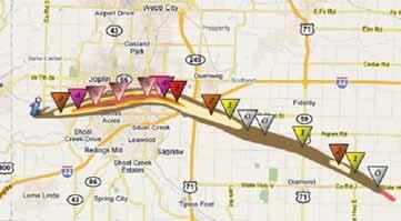
Mapping of the Joplin Tornado EF Rating. Courtesy of the United States Department of Commerce, National Weather Service, Central Region Headquarters, Kansas City, MO.
Structural steel and concrete framed buildings performed better in resisting the extreme wind effects of the tornado, although not without damage. St. John’s Hospital and its Medical Office Buildings sustained damage, but the structural frames remained stable. The buildings’ envelope materials were severely damaged, with most of the destruction caused by the ballasted roof systems used throughout the complex. Essential facilities should consider a comprehensive tornado preparedness plan when considering the layout of the facility and the respective infrastructure requirements. Emergency generators, electrical switch gear, mechanical systems and the structures that support them require consideration of the implications of windborne debris. Reports indicate that cars impacted the backup generator building for the hospital during the tornado, which rendered the facility inoperable. Hard wall structures are a building type that is constructed to be very efficient in the use of materials, while providing the most building square footage for the minimum amount of cost. These buildings are commonly described as “big box stores.” A few such buildings experienced a near-direct hit by the tornado. The high wind speeds caused significant damage, including roof deck connection failure, leading to the failure of several structural framing members and, in some cases, almost total collapse of the hard wall system. The roof deck diaphragms of buildings have a propensity to fail first when tornado winds impose high uplift on the structure. This was most evident in hard wall buildings that the committee reviewed where roof framing was light and material usage was efficient. Roof
deck diaphragms are an essential building component that typically does not incorporate a redundant load path; once it fails, other structural members will likely fail, as seen in both of the hard wall structures investigated. It is understood that tornados are an extreme loading event, with a low probability of occurrence, but it is also evident that society is impacted by these events. As professionals, structural engineers need to lead in determining if and when enhancements to the building codes are warranted. We understand that most buildings do not need to be designed to the maximum wind speeds of a tornado to provide life safety, but we need to be prudent and consider these potential events to some extent.
Summary of Recommendations
The intent of the following recommendations is to increase life safety for occupants and overall building integrity and robustness when impacted by tornado type winds. However, it should be understood that a structure St. John’s Hospital damage; note the ballasted roof, lightweight concrete and glazed curtain wall destruction. built in accordance with them will not be “tornado proof.” 1) Implement statewide building code legislation in all allowing it to occur within the connection. Connection failures are 50 states. often sudden and catastrophic, whereas member failures tend to be The public has the opportunity to enhance the built environment more ductile and may not result in a catastrophic failure. The Engineer by passing legislation requiring compliance with an appropriate of Record or joist manufacturer should design the connection based building code. Such legislation is currently being considered in the on the strength of the most critical component of the joist or joist state of Missouri, and at least fifteen other states have already enacted girder assembly, such as top chord shear or end diagonal compressuch a provision. This legislation should enable local jurisdictions sive capacity. to enforce the statewide building code and include funding for this 5) Develop code requirements for greater robustness or enforcement. Studies have shown that a building code provides a safer redundancy in hard wall buildings. These may be in the built environment for all. form of specifying: a defined base moment; a maximum
2) Determine if the use of mechanical deck connections for length of continuous wall prior to a full-height lateralsteel metal deck thicknesses of 22-gauge or less should load-resisting member, wall or frame; or a system of be mandatory. continuous cross-ties.
The roof diaphragm is essential to the overall integrity of a building’s One of the buildings impacted by the Joplin Tornado experienced structural system. Inspections by several groups have revealed failures a near-total collapse of the tilt-up wall panel system except at the of the decking metal around supposedly sound arc-spot (puddle) loading dock area, where the base of the panel was well below grade welds. Today, steel deck manufacturers and their governing bodies such that it behaved as a cantilever. Details could be designed and do not recommend welding of side laps for 22 gage decks. It seems provided that would offer a fixed or partially restrained base condition. apparent that this may need to be considered for typical fastening of Alternatively, if a lateral bracing element, such as a perpendicular wall the deck to the supporting structure. or steel brace, is placed to restrain the wall system at some prescribed 3) Design roof deck fasteners considering simultaneous uplift length, the potential for failure of a significant portion of the wall tension and diaphragm shear and reflecting the different system is greatly reduced. factors of safety in accordance with the [Steel Deck Institute Building codes should also include requirements for more robust
Diaphragm Design Manual], Third Edition. continuous ties across the roof diaphragm so as to preserve walls when Steel deck manufacturers’ data typically does not consider tension the diaphragm fails. Wind force levels could correspond to EF-0 or and shear simultaneously, and at times will provide notes regarding EF-1 and allowable stresses could be ultimate, with a factor of safety the different factors of safety for wind and seismic. Inspection of equal to 1.0. This would allow significant damage, but minimize the damaged structures indicates that uplift in the field of the roof may propensity for collapse of the hard wall system. have been much higher than traditional loading patterns currently 6) Require a storm shelter, or at a minimum an area of refuge, indicate. This is likely due to the large atmospheric pressure drop in in retail stores, manufacturing buildings and similar the vortex of a tornado. There is little or no available research into types of structures with a certain number of occupants, the wind patterns on a structure during a tornado, but designing the for employees and customers that may be inside during a fastening of the diaphragm system for an amplified wind pressure tornado event. load capacity in both shear and uplift seems appropriate. According to published accounts, lives were saved in one hard wall 4) Require a specific design for open web steel joist building because store employees and patrons were able to shelter connections to primary framing members and joist girders. themselves in an employee break room. Although not specifically In many instances, connections between joists and joist girders designed as a storm shelter, the inherit robustness and redundancy in and between joist girders and building columns are standard details the framing of the room provided sufficient protection for the occuprovided by the joist supplier. These details need to reflect the design pants who took refuge there. Design could be based on the principles practice of forcing any failure into the member itself, rather than of ICC-500, ICC/NSSA Standard for the Design and Construction of
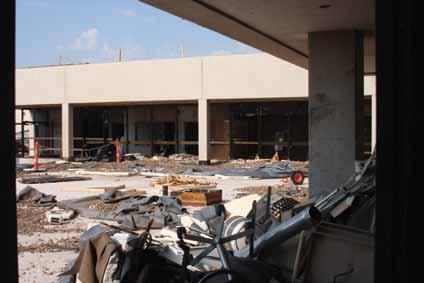
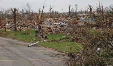
Devastation near the center of the path of the EF-5 Joplin Tornado.
Storm Shelters, and FEMA 361, Design and Construction Guidance for Community Safe Rooms.
7) Require storm shelters designed in accordance with ICC500 and FEMA 361 for all elementary, middle and high schools, as well as other critical facilities, such as police and fire stations, emergency preparedness centers of control and other post-disaster structures including hospitals.
Society relies on the public school system to protect their children while they are being educated, and expects critical facilities and infrastructure to withstand extreme loadings. The tornado that struck Joplin provides sufficient evidence that schools need to consider alternative measures for offering security during these times of violent weather. It is very fortunate that, at the time of the tornado, the schools were empty. It is unfortunate that some of the critical facilities were unusable after the event.
8) Require essential buildings to have impact-resistant glazing systems and door units, similar to those required in hurricane-prone regions.
The winds of the Joplin Tornado caused significant damage to envelope materials of several important buildings, including the St. John’s Hospital complex. The hospital facilities may have been able to treat some of the injured had these items not catastrophically failed. Critical structures should conform to the same practices required in regions where windborne debris is a concern during a hurricane.
9) Prohibit the use of ballasted roofs in all construction.
During high wind events, both hurricanes and tornadoes, loose roof ballast is ineffective at preventing roof blow-off. In fact, roof ballast often becomes airborne debris that typically destroys glazing systems and exterior finishes and may directly injure people. Many hurricane-prone regions of the country have enforced codes restricting or eliminating their use.
10) Research the concept of implementing similar design considerations for wind load distribution to diaphragms, drag struts and chord attachments in high-risk tornado areas that are currently codified for seismic lateral force distribution.
Enhanced design requirements for diaphragms, drag struts and chord development will lead to more robust connections of the diaphragm to the bearing walls and to other lateral-force-resisting system elements. The research should consider all aspects.
11) Enhance inspection requirements for big box structures.
Adopt provisions similar to those in the Florida Building Code, which requires a “threshold inspection” for all structures over a certain size.
12) Review and update prescriptive practices for wood construction to ensure a robust load path through connections, from roof to foundation.
Connections in wood with nailing procedures as outlined in prescriptive guidelines should be reviewed, for both the International Residential Code (IRC) and the IBC. Several studies indicate that simple, low-cost modifications can achieve significant robustness in the load path; for example, metal plate connections for roof trusses, top plates and sill plates.
13) Place renewed emphasis on special inspections, with improvements for wood framed buildings, including residential.
As design and construction professionals, we should review our past practices and determine ways to enhance them to serve the public better. In the wake of a disaster, there tends to be a renewed effort in inspections and other requirements for design and construction. Several cities around the country have developed their own special inspection manuals that typically are more stringent than a recognized building code.
14) Encourage installation of tornado shelters in existing buildings.
There are several available pre-manufactured storm shelters that satisfy FEMA 320, Taking Shelter from the Storm: Building a Safe Room for Your Home or Small Business. The guidelines offer simple and economical methods to designing and constructing residential structures. This document, along with others regarding tornado preparedness, is available at www.fema.gov.
15) Study the impacts to design and construction practices if codes required the design of buildings for EF-1 or EF-2 tornados in tornado-prone areas.
It seems appropriate to consider the design of structures for a higher level of wind pressures, based on the current observed wind speeds through the Enhanced Fujita Scale Rating System. However, we must realize that these wind speeds are estimated from observed damage and not measured directly.
16) Study tornados further in an effort to develop appropriate code design equations.
The current equations consider straight-line winds, which are significantly different from winds near the vortex of a tornado, where uplift forces are considerably higher and turbulence occurs. Tornados are one of nature’s most elusive adversaries to the built environment. Although modern technology has enabled the prediction of potential tornadoes and their possible paths, it is still a struggle to record wind speeds and develop structural design methodologies based on actual conditions. This is an opportunity for design professionals, the construction industry, government agencies and the general public to learn from these devastating events and react to these recommendations. Readers are encouraged to conduct further research by reading other Joplin reports that have been or will be issued by the National Institute for Standards and Technology (NIST), Federal Emergency Management Administration (FEMA), and National Oceanic and Atmospheric Administration (NOAA), along with reports regarding the Tuscaloosa, Alabama tornado and Enhanced Fujita (EF) Scale developed by Texas Tech University (TTU) in cooperation with the National Weather Service (NWS) in 2004, www.spc.noaa.gov/efscale/ef-ttu.pdf. ▪
Curtis Geise, P.E., S.E. (CGeise@HNTB.com), is a structural engineer at HNTB Corporation in Kansas City, Missouri. He is a past president of the SEAKM Kansas City Chapter and chaired the SEAKM committee that studied the aftermath of the Joplin Tornado.


We’re stacked in your corner.
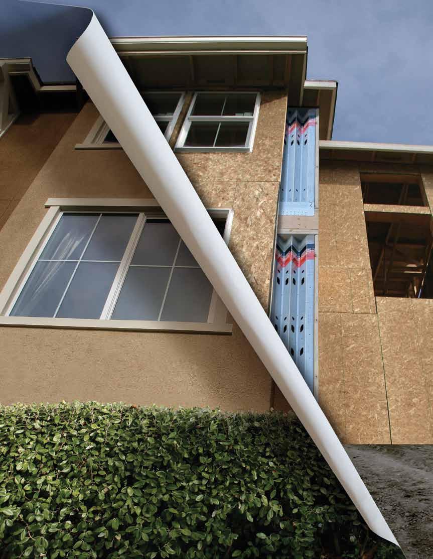
If you’re planning to stack prefabricated shearwalls, make sure they’re Steel Strong-Wall® shearwalls. The Simpson Strong-Tie two-story solution is not only code listed, but can be installed right at the corner to save wall space. And since our engineered shearwalls are available in widths as narrow as 15 inches for stacked applications, you can design multistory homes with larger windows, doors and open spaces without sacrifi cing the high load values required for the project. To ensure your walls stack up, look to Simpson Strong-Tie for the widest selection of shearwalls code listed to the 2009 IBC (see ICC-ES ESR-1679). Visit www.strongtie.com/strongwall or call (800) 999-5099.
