26 minute read
LESSONS LEARNED


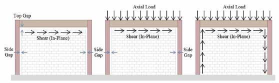
Figure 1. Hybrid masonry systems: (a) Type I; (b) Type II; (c) Type III. problems and solutions encountered by practicing structural engineers
In the May 2016 issue of STRUCTURE, Part 1 of this series addressed through-bolts in masonry walls. That article was based on hybrid masonry research funded by the National Science Foundation’s Network for Earthquake Engineering Simulation Research (NEESR), but the information provided is useful to all designers of masonry construction where through-bolts are useful. The goal of this article is to further help practitioners gain a better understanding of the behavior of three particular types of connectors; these are hybrid “link” and “fuse” connectors, as well as headed stud anchors. While the “link” and “fuse” connectors are specific to hybrid masonry, the headed stud anchors are not.
Hybrid Masonry Overview
Refer to the Part 1 article for an overview of hybrid masonry. The system is composed of a structural steel frame and reinforced concrete masonry panels. Hybrid Masonry offers a design alternative to braced frames and moment-resisting frames that is appropriate for low and mid-rise construction. It is best suited for projects where a structural steel framing system and masonry walls would naturally be chosen due to structural and architectural efficiency. Figure 1 shows, graphically, the three distinct types of hybrid masonry. In Type I hybrid masonry (Figure 1a), steel connectors transfer in-plane shear between the steel frame and the top of the masonry panel. These connectors can be either rigid “link” plates or ductile “fuse” plates. The connectors do not transfer any vertical load to the masonry wall, but their design can have a significant influence on the overall performance of the system. This particular situation makes the wall design a non-loading bearing shear wall. In Type II and III hybrid masonry (Figure 1b and 1c), Hybrid Masonry Connections and Through-Boltsheaded studs are used to transfer shear from the beam and/or columns to the masonry panel. Part 2 Vertical load is also transferred directly through contact from the beam to the top of the masonry By Gaur Johnson, Ph.D., S.E. and panel. This instance makes the wall design a load Ian Robertson, Ph.D., S.E. bearing shear wall.
Type I Connections
As mentioned, the steel connector plates used in Type I Hybrid Masonry can be designed either as elastic “link” connectors or as ductile “fuse”
Gaur Johnson is an Assistant Professor at the University of Hawaii at Manoa. Guar can be reached at gaur@hawaii.edu. Ian Robertson is a Professor of Structural Engineering in the Department of Civil and Environmental Engineering at the University of Hawaii at Manoa. Ian can be reached at ianrob@hawaii.edu.
The online version of this article contains detailed references. Please visit www.STRUCTUREmag.org.
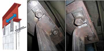
Figure 3. Original bent plate concept with non-ductile weld failure mechanism. Courtesy of International Masonry Institute, www.imiweb.org.
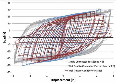
connectors. In both cases, the intent is for the connector plates to transfer only lateral and in-plane shear from the steel frame to the top of each concrete masonry panel. “Link” connectors are designed to remain elastic during a design level seismic event, while the concrete masonry wall is designed with sufficient ductility to absorb the necessary lateral displacement during the earthquake. Post-earthquake repair will likely require replacement of some of the ductile masonry walls. Ductile “fuse” connectors are designed to remain elastic during wind and low seismic events, but to yield and provide hysteretic energy absorption during moderate to high seismic events. Fuses which are tapered to provide an equal potential for yielding along a significant length of the connector provide the best energy dissipating behavior. These fuses provide a high degree of ductility to the system. The masonry wall is designed with an appropriate overstrength factor so that it remains essentially undamaged during the earthquake. Post-earthquake repair will involve only the replacement of damaged fuses. The tapered ductile fuse design was one of the several prototypes initially evaluated using cyclic quasi-static testing of individual fuses. To study the behavioral effects of Figure 4. Successful bent welded fuse connector plates on either side of beam to simultaneously load- masonry panel connection. ing multiple fuses, wall tests using both four and six tapered duc- panel. A third alternative developed was to tile fuses to transfer the load were conducted. weld side plates to the flanges of the steel Figure 2 (page 33) compares the hysteretic beam and then either bolt (with slip critical response of the wall test using six fuses with bolts) or weld the fuse or link plates to these hysteretic responses of other tests using one or side plates as shown in Figure 5 (Ozaki-Train four fuses. The loads were scaled, as indicated, et al., 2011). The advantage of the bolted to facilitate a direct comparison. configuration is the ease of fuse replacement after a damaging seismic event. Steel Connector For each of these connectors to function Plate Attachment correctly, it is essential that the through-bolt connection between the masonry panel and Several fuse and link plate configurations were the fuse or link plate can transfer the required considered and tested as part of the NEESR load without premature failure. The throughproject on hybrid masonry. The original con- bolts were discussed in Part 1. cept of a bent plate welded to the bottom flange of the steel beam, as shown in Figure 3, showed an undesirable non-ductile weld Type II Connections failure (Goodnight et al., 2011). A second Type II hybrid masonry requires a connection bent plate configuration shown in Figure 4 between the steel beam and the top of the proved more successful at transferring the concrete masonry panel that transfers both inlarge shear loads from steel frame to masonry plane shear and vertical load. One approach
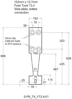
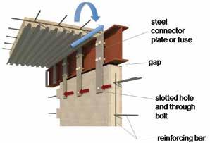
Figure 5. Link connectors (a) or ductile fuse connectors (b) and (c) attached-to-beam side plates using slip critical bolts or welds (Dimensions in mm; 1mm = 0.0394 in). Figure 5a courtesy of International Masonry Institute, www.imiweb.org.
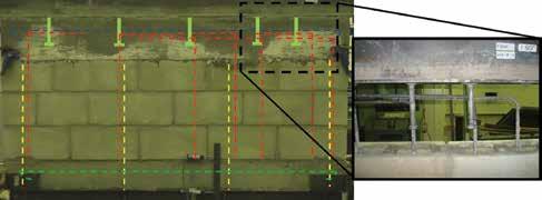
Figure 6. Hybrid masonry type II test wall showing the location of reinforcement and headed studs.
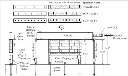
Figure 7. Type II headed stud connection testing setup. to achieving this load transfer is the use of headed studs welded to the bottom flange of the steel beam and embedded in a grout beam at the top of the masonry wall (Figure 6 and 7). Figure 7 shows the test setup used to conduct cyclic quasi-static loading tests on the Type II connections made with headed studs. Non-linear behavior is restricted to the ductile masonry panel, so the headed stud connection should be designed for elastic response using an appropriate overstrength factor.
Headed Studs Embedded in a Grout Beam
The American Institute of Steel Construction’s (AISC) 360-10 provides design guidance for the use of headed studs to transfer load for composite structural steel beams and columns. Headed stud embedment in a grout beam at the top of a CMU wall is the primary load transfer mechanism for Type II hybrid masonry systems. Limited testing was conducted to observe local failure mechanisms associated with the load transfer from the steel beams through headed studs, the grout beam, and into the top course of a CMU wall. Three tests were conducted to verify if the AISC specifications were valid for this case. Details regarding the reinforcement and testing protocol were documented in a research report and paper at the 12th NAMC (Aoki and Robertson, 2013; Aoki et al. 2012; Johnson and Robertson 2015). The results were compared with the AISC 360-10 provisions as well as code specified limit states from TMS 402-13 (The Masonry Society) and ACI 318-14 (American Concrete Institute). The TMS 402-13 limit states of masonry breakout at anchors, masonry
Table 1. AISC headed stud capacity.
Number of Studs
AISC Grout Failure [28.5 k /stud]
AISC Stud Failure [21.5 k /stud]
crushing at anchors, bearing, and shear and ACI 318-14 limit state of shear loading of anchors were considered. The AISC headed stud specification, and limitations, as described in the commentary, are summarized below. AISC 360-10 Section I8.2a Shear Studs specifies the in-plane shear transfer capacity for studs embedded in solid or composite slabs. This section is not intended for use when there is an edge in the vicinity of the studs unless concrete breakout in shear can be prevented by confinement (AISC 2010) – there is no specific guidance to determine if there is sufficient confinement. Qn = 0.5Asa √f'cEc ≤ RgRp Asa Fu
For the hybrid masonry case, the grout beam was formed using the grout which filled the CMU. The grout compressive strength was tested in accordance with ASTM C1019 and used in place of f'c in the AISC equations including the calculation of Ec. The AISC equation predicts a nominal capacity of 21.5 kips based on the shear studs (right hand side of the inequality), which was less than 28.5 kips that AISC predicts based on the capacity of the grout (left hand side of the inequality). Table 1 indicates the AISC predicted total capacity of the headed stud connection based on grout failure, stud failure as well as the maximum experimental load, and the average experimental load per stud. A user note in AISC Section I8.3 states that the provisions are not intended for hybrid construction where the steel and concrete are not working compositely, such as with embed plates (AISC 2010). The section accounts for steel anchor failure and concrete breakout in shear. Geometric limitations of the studs are formulated to preclude anchor pry out and concrete breakout in tension. The commentary states, “…if these provisions are to be used, it is important that the engineer deem that a concrete breakout failure mode in shear is
Maximum Experimental Load
Average Experimental Load Per Stud
Failure Mechanism
4 114 k 86 k 60.1 k 20.0 k* Break-out Stud Failure
5 143 k 108 k 89.0 k 17.8 k Masonry Shear Wall Failure
10 285 k 215 k 95.2 k 9.5 k Masonry Shear Wall Failure
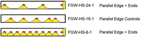
Figure 8. Assumed geometry applied to the ACI 318 shear loading of anchors provisions.
Table 2. ACI318 and TMS 402 breakout predictions for headed studs.
Number ACI 318-14 TMS 402-13 Masonry Experimental of Studs Shear Loading of Anchors Breakout at Anchors Maximum Load 4 7.30+2(8.99)+2.74 = 28.0 k 3(24.5)+6.13 = 79.6 k 60.1 k 5 3(8.99)+2(7.30) = 41.6 k 5(24.5) = 123 k 89.0 k 10 9(5.73)+2.74 = 54.3 k 9(24.5)+6.13 = 227 k 95.2 k
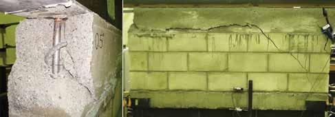
Figure 9. Breakout failure of test specimen with 4 headed studs.
directly avoided through having the edges perpendicular to the line of force supported, and the edges parallel to the line of force sufficiently distant that concrete breakout through a side edge is not deemed viable… the determination of whether breakout failure in the concrete is a viable failure mode for the stud anchor is left to the engineer. Alternatively, the provisions call for required anchor reinforcement with provisions comparable to those of ACI 318 [for anchors]” (AISC 2010). Applying anchor shear loading provisions of ACI 318 results in breakout failures shown in Figure 8. The figure is a cross-section through the length of the wall specimens. The circles show the locations of the studs. The concrete which is assumed to breakout is also shown. Note that in-plane loading results in breakout of the concrete at the parallel edge. Table 2 shows the ACI and TMS predictions controlled by the breakout of anchors compared with the maximum experimental loads. The ACI 318 provisions are conservative, while the TMS provisions overestimate the capacity of the specimen with 4 studs, which failed at the grout beam and appeared to be initiated at the headed studs. The other two specimens failed within the CMU wall after the load was transferred through the headed stud connection. The authors suspect that the high average force required of each stud caused the breakout type failure for the specimen with 4 studs, and the lower average force per stud precluded a stud initiated failure for the specimens with more studs. Figure 9 shows the breakout and splitting failure of the grout beam with 4 studs.
Conclusions
Practitioners who would like to use connection details described in this article will not be able to find code language or limit states that directly address the behavior, boundary conditions, and loading which can make these connections cost effective for hybrid masonry systems. They will need to rely on engineering judgment and should consider the following information. Steel Connecter Plates & Fuses • Welded connections commonly used in conjunction with bent plates attached to the bottom flange of W sections, to provide lateral restraint at the top of masonry walls, should not be used to transfer shear forces parallel to the wall. The C-shaped weld is required to resist shear, torsion, and flexure.
The AISC Manual does not provide tabulated capacities for this case. Even weld analysis by the instantaneous center of rotation method or elastic method may not provide conservative capacities considering the relatively large deformations within the bend of the plate that are immediately adjacent to the beginning of the weld. • Details which eliminate the 90-degree bend in the plate and transfer the loads directly to either the top flange or web of the beam can provide the restraint and capacity needed to transfer in-plane shear loads. • Highly ductile fuses can be designed to limit the force transferred through these connections, thereby reducing damage to the masonry panels. Regions of equal potential for yielding within the fuse are critical to achieving a ductile response. Use of Headed Studs Embedded in a Grout Beam • Do not count on the full capacity of the stud as documented in AISC 36010, which is intended for shear transfer from a beam into a slab which provides significant lateral confinement to the concrete in the vicinity of the shear stud. Indeed, the AISC commentary expresses the importance of using a design which precludes a breakout failure as defined by ACI 318. • TMS 402-13 anchor related limit states do not account for the thin geometry of the grout beam detail and resulted in unconservative predictions of failure load for the limited number of tests reported here. • ACI 318-14 shear loading of anchor bolts limit states provide a conservative estimate of the capacity. • Too few tests with headed stud failures are available to make any code change recommendations. However, observed failures indicate that the following details are good practice to reduce the potential for early break-out failure of the grout beam. ° Headed studs should be placed at least 12 inches (305mm) from the end of the CMU. ° Headed studs should be placed in the center of the grout beam to provide maximum edge distance to each side of the grout beam.▪
By Steven B. Tipping, S.E. and Gina T. Phelan
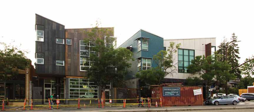
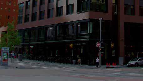
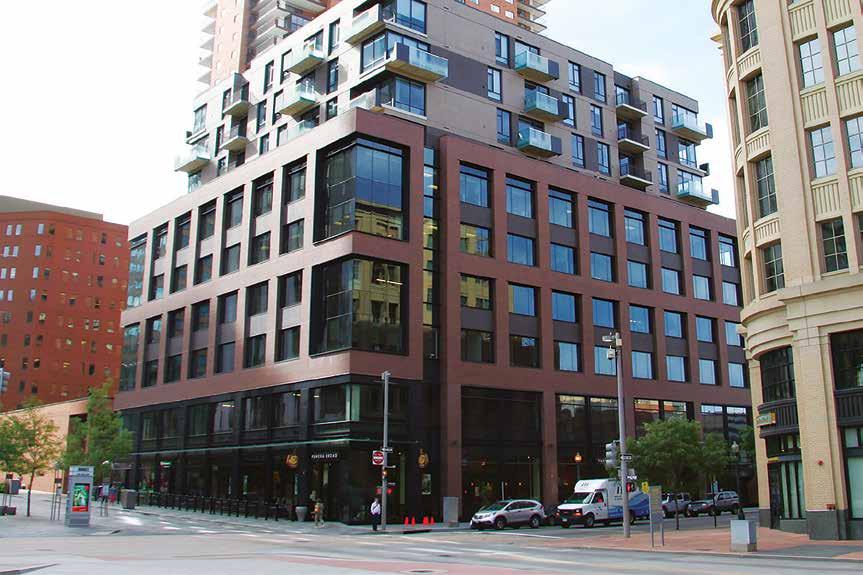
1908 and 1906 Shattuck.
It is not often that a new building’s structural engineer is also its developer – and the synergies arising from this pairing are equally rare. How can seemingly opposing priorities and objectives combine positively? How can a developer’s challenges transform into innovative seismic engineering opportunities? The Tipping Structural Engineers (TSE) mixed-use project at 1908 Shattuck Avenue in Berkeley, CA, is that unique result of the interdependence between creative engineering and real-estate development strategies.
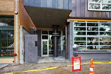
1908 Shattuck Avenue
TSE – whose existing offices at 1906 Shattuck are immediately adjacent – developed and designed the project to accommodate their increasing numbers. The structure accommodates a restaurantbrewery at street level and an office space designed for 25 people on the second and third floors. Its superstructure comprises two stories of wood-frame construction, totaling about 4,800 square feet, with a lateral system consisting of a series of distributed wood shear walls sheathed with half-inch plywood. Supporting the superstructure are six cantilevered columns and a 14-inch-thick post-tensioned concrete podium slab. Lastly, a series of crossing grade beams measuring 6 feet wide by 3 feet deep make up the building’s foundation system. The downtown Berkeley infill site, measuring only 39 feet by 90 feet in plan, is less than a mile west of the Hayward Fault, considered to be the most active fault in the country, with a 31 percent chance of releasing a magnitude 6.7 earthquake in the next 30 years. A primary goal of the project was to develop a structural system that reflected quintessential Tipping engineering – effective, cost-efficient, projectspecific design thinking. Given this project’s location, seismic isolation was quickly identified as the best way to achieve this goal, resulting in perhaps the smallest isolated commercial building in the United States.
Planning and Development Challenges
The City of Berkeley is well-known for its stringent zoning codes and building requirements. For 1908 Shattuck, a combination of these limited the size of the building to a maximum of 7,500 gross square feet, its height to 40 feet, the number of stories to 3, and the use of the ground floor space to only retail, which constrained the office space to the upper two floors. Also, the zoning code would have dictated a 25-foot setback at the west side of the property (which borders a residential lot), losing TSE almost 2,500 square feet of usable space. To clear this zoning hurdle and maximize the size of the new building, the developer-engineers decided to merge 1906 and 1908 Shattuck into one property, which drastically reduced the setback requirements. Furthermore, the merger allowed both buildings to share a common entry (from the street to the second floor) as well as the existing building’s elevator and above-ground parking garage.
Idiosyncratic Isolation
Once the basic geometry of the building was set and the planning and development issues resolved, the engineers turned to designing the seismic isolation system, which became the single most compelling feature of 1908 Shattuck. Isolation bearings are typically installed below grade, hidden from view, requiring intensive – and expensive – foundation work. As it happened, previous construction had left retaining walls on three sides of the lot to accommodate a grade change of about eight feet over the depth of the site. This fortuitous condition spurred the engineers to envision alternative isolation configurations. They decided to expose the bearings. Spliced into the ground-floor columns ten feet above grade, they are visible to the patrons of the restaurant. The façade was designed so that one column stands outside, viewable by the public from the street.
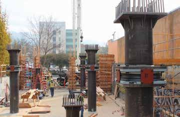
Building the column and isolator assembly.
Traditional base isolation systems require a ground-level “moat” that allows the isolated building freedom to move during an earthquake. Splicing the isolation bearings into the columns above grade resulted in an atypical isolation plane requiring a different approach: groundfloor walls cantilever from the foundation and an isolation moat was designed at the second story. All in all, this idiosyncratic isolation design resulted in a more cost-efficient solution than traditional below-grade installations, an outcome sweet to any developer’s ears. Because of the site’s proximity to the Hayward fault, practice would dictate isolation bearings with an allowable horizontal movement of roughly 36 inches. Installing such bearings would have resulted in a building 33 feet wide at the maximum. Given the small lot size and the architectural program, TSE was reluctant to forego so much real estate – having originally planned for a 35-foot-wide building. The engineers recognized that the only way to achieve this would be to employ isolators with a smaller allowable movement, specifically, 24 inches. To that end, they worked with Earthquake Protective Systems (EPS) in Vallejo, CA, to customize six stock triple-pendulum bearings.
Lock-Up Potential and Mitigation
The next step was to test a customized bearing. EPS ran multiple ground motions at maximum-displacement earthquake (MCE) and design-basis earthquake (DBE) hazard levels. They confirmed that the median displacement under DBE simulations would be 11 inches with an associated shear force of 40 kips, and under MCE simulations, 22 inches with an associated shear force of 50 kips. Significantly, two of fourteen analyses caused the isolator to “lock up,” or reach the 24-inch allowable displacement capacity, resulting in a shear force of 150 kips. To account for the slight probability of lock-up, the engineers designed the cantilever columns with a diameter of 24 inches instead of 20 inches, which would allow them to remain elastic at lock-up. Further, to analyze the effect that locking up would have on the superstructure, they modeled every wood wall. Based on those results, they concluded that all the walls had to be sheathed with plywood, in some cases on
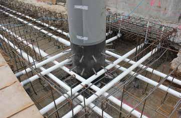
Column embedment at the grade-beam intersection. PVC tubes hold posttensioned high-strength bars.
both faces, to achieve the desired elastic behavior. Lastly, to allow the footings to yield, displace, and then self-center in the event of an earthquake force larger than the lock-up, the foundation’s grade beams were reinforced with post-tensioned high-strength steel rods. All these design strategies added cost to the project; however, the gain in the programmable square footage was a tradeoff well worth the expense.
Statewide Seismic Monitoring
TSE submitted 1908 Shattuck to the California Strong Motion Instrumentation Program for inclusion in the statewide monitoring system. It was accepted on the basis of two unique aspects: 1908 will be the first isolated building employing a wood shear-wall lateral system; and the adjacent existing office building, constructed about twenty years ago, is structurally identical to 1908, with the exception of the isolation bearings. Both buildings are hard-wired to transmit data via satellite to a data center in Sacramento, CA. The new building is equipped with sixteen, three-axis sensors, the older building with six. The sensors were positioned to capture the translation and rotational components of each building’s seismic response.
Lessons for Everyone
The knowledge and advantages gained in planning, designing, and constructing 1908 Shattuck need not benefit only the developer-engineers at TSE. In fact, Steven Tipping is hopeful that each innovation and design strategy inspires others, and ultimately informs the profession. As engineers go about their practice, learning to think like a developer and being empathetic to a developer’s project goals can multiply the possibilities at their disposal – both in serving clients and in creating cutting-edge engineering solutions. “When structural engineers abandon their silos to ask the bigger questions, the profession can only grow and flourish,” advises Tipping. “What’s best for the whole project? What’s best for all the players – the owner, the architect, the other disciplines, the trades? How can our work improve the built environment at large?”▪
Project Team
Owner: Steven B. Tipping Structural Engineer: Tipping Structural Engineers (initiated as Tipping Mar) Architect: Fernau and Hartman Architects General Contractor: Oliver and Company Steven B. Tipping is founding Principal at Tipping Structural Engineers in Berkeley, CA, and has many of the firm’s awardwinning innovations. He can be reached at s.tipping@tippingstructural.com. Gina T. Phelan is an Associate at Tipping Structural Engineers and serves as strategic development director. She can be reached at g.phelan@tippingstructural.com.
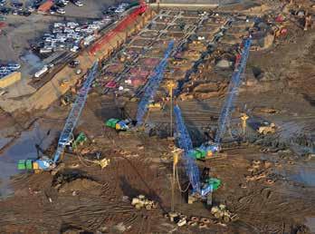
REPAIR FOR LOW CONCRETE BREAKS ON DOWNTOWN DENVER PROJECT
By Orville “Bud” Werner II, P.E.
It is an unprecedented time to be working in Denver. Individuals and businesses are relocating at a swift pace to the city, recognizing its natural beauty, strong business climate, and forward-thinking leadership. In fact, the city’s projected growth rate over the next ve years is more than four times the national rate, according to e State of Downtown Denver, a report released last year by the Downtown Denver Partnership. As the city’s density increases, the number of parcels available for development in the downtown area will shrink. According to Denver’s Open Data (City and County), only about 3 percent of the parcels within the City and County are vacant land. As a result, developers are willing to consider more extensive remediation of brown eld sites for their projects. Against this backdrop of facts, the design team wrestled to identify solutions for a notable downtown project: 16M. is LEED-certi ed, mixed-use commercial site houses 115,000 square feet of o ce space over ve oors, 36 luxury apartments on the top four oors and 13,000 square feet of retail space. is project’s layout speaks to how developers can manage tighter spaces and smaller lots – and overcome the issues that may result. When work was well underway on 16M, a concrete producer for the project contacted CTL| ompson after the concrete at the second oor parking deck did not achieve the speci ed design strength. e structural engineer of record carefully analyzed the slab using the lesser strength achieved and found a region of the slab that would not provide adequate support for the design loads, as built. e exural strength in this area of the concrete slab was insu cient when analyzed using the reduced concrete strength. No one on the project anticipated this problem. In fact, many steps were taken to ensure a smooth build. Early tests indicated that the concrete met the required design strength, yet some pours did not perform as expected. e project team faced practical – and potentially costly – concerns as to whether to tear out and replace the existing slab, which would disrupt and delay work on the building. When CTL| ompson’s materials lab team received the call, most of the project design team, with years of experience in high-rise construction, considered slab replacement to be the presumptive repair option. CTL| ompson expected this option to come with a high price. Another option considered included new support beams below the problematic area. is option was also expensive and potentially unacceptable, as it would limit clearance in the main driveway location of the lower level parking lot. Prior work with Department of Transportation and road and bridge developers led to the suggestion that carbon ber be used to improve the strength of the area in question. is solution could be implemented with the concrete in situ, preventing the need for a teardown. Commercial construction rarely needs such a x, as it is primarily used to reinforce roads and bridges, but the rm believed it would work and careful study bore out the results. Carbon ber material has been used for more than two decades and possesses a strength that is signi cantly higher than steel reinforcement in concrete. e Colorado Department of Transportation uses it occasionally on bridge repair and highway construction projects. e strong, thin layer of carbon bers, encapsulated in a resin lm, can be adhered with epoxy to the surface of concrete, akin to putting a cast on a broken arm. In this case, when installed
below reinforced post-tensioned concrete, the carbon ber places additional tensile reinforcement at the bottom of the slab. is lower layer of tensile reinforcement increased the e ective depth of the slab su ciently to reduce the compressive stress at the top of the slab to within the capacity of the reduced concrete compressive strengths. e unique application provided a structurally sound repair that, in the small area, required less than 500 square feet and was far less costly than replacement. Most importantly, the application allowed the existing concrete to stay in place and work to continue. External tensile reinforcement uses strong, exible bers that are not subject to corrosion – a key consideration for structures such as parking garages, which are exposed to aggressive levels of sand and road salt in the Denver climate. ere are other advantages of using carbon ber in this type of application, such as: • ere is no compromise in the oor-to-ceiling clearance in the area of repair. • e repair is nearly invisible to passing occupants or visitors.
Anyone looking closely at the underside of the slab in the area of the understrength concrete would see only a slight di erence in texture and color compared to the rest of the underside of the slab. • Where other repair methods include a risk of damaging steel during concrete removal, this repair required no cutting or chipping into the concrete that encases the existing unbounded tendons. After additional discussion and investigation, including the structural engineer of record’s evaluation and endorsement, the developer recognized this solution as the best possible scenario – one that was safe, e cient, and kept construction on schedule. e case of 16M has shown that viable solutions to initially perplexing problems exist, even if they are borrowed from other elds. Success is based on the ability to develop a strong coalition among the contractor, the supplier, specialty repair contractors and the engineer of record. is healthy working relationship among all parties involved led to an outcome at 16M that minimized the expense of repair and retained the structure’s value.▪
Orville “Bud” Werner II is Principal of CTL| ompson & President of its division, CTL| ompson Materials Engineers Inc. He can be reached at owerner@ctlthompson.com.
Project Team
Owner: Integrated Properties Structural Engineer: Monroe and Newell Architect: Gensler General Contractor: Milender White Construction Repair Contractor: Restruction Corporation Materials Consultant (for repair): CTL| ompson, Inc.
ADVERTISEMENT–For Advertiser Information, visit www.STRUCTUREmag.org
DESIGNED not to be seen

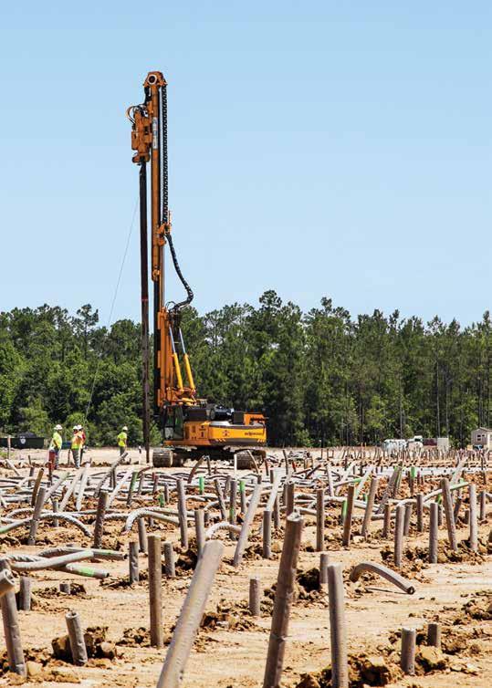
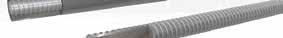
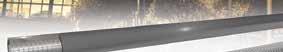
Micropile
courtesy of nascarhall.com. Photo
Systems
Large Bar • Hollow Bar • Multi-Bar

NASCAR Hall of Fame Charlotte, North Carolina
All-Thread Bar with Steel Casing
Williams Multi-Bar Micropile System
Large Bar Micropiles:
Geo-Drill Injection Bar
• Excellent choice for underpinning or emergency repairs — can be installed in virtually any ground condition with minimal vibration and disturbance to existing structures. • Right-handed threaded Grade 75 All-Thread Rebar in #14 – #28 along with a selection of reducer couplers that can adapt to space together any larger size bar to any small size. • Grade 80 to 100 All-Thread Rebar, as well as 150 ksi All-Thread Bar (as alternative for micropile design application upon request).
Hollow Bar Micropiles:
• Accepted by the FHWA in the Micropile Design and Construction Guidelines Manual, Hollow Bars are being used increasingly for micropile applications as the reinforcement bar choice in collapsing soil conditions because of their increased bond stress resultant from the simultaneous drilling and grouting operation. • Using sizes from 32mm – 76mm, these bars offer up to 407 kips of strength, up to 3.88in2 of cross sectional reinforcement area, and their selection modulus provides considerable bending resistance.
Multi-Bar Micropiles:

• Used for attaining ultra-high load carrying capacity. High-rise office buildings and condos are construction examples where such high load carrying micropiles (mini-caissons) are used. • Designed to specific contractor specifications and shipped to the jobsite fabricated in durable cages for quick installation.

Williams Form Engineering Corp. has been a leader in manufacturing quality products for the customer service, for over 80 years.
Belmont, MI 616.866.0815
San Diego, CA 858.320.0330 Golden, CO 303.216.9300 Lithia Springs, GA 770.949.8300 Kent, WA 253.854.2268 Portland, OR 503.285.4548 London, ON 515.659.9444 Collegeville, PA 610.489.0624 For More Information Visit:
williamsform.com