23 minute read
HISTORIC STRUCTURES


significant structures of the past
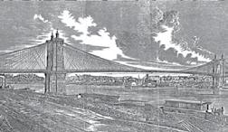
Abridge across the Ohio River connecting Cincinnati, Ohio, and Covington, Kentucky, was suggested in the 1820s. A charter for the bridge was granted in 1826 by the State of Kentucky and a second charter approved by Kentucky in 1840. Charles Ellet, Jr. (STRUCTURE, October 2006) submitted a plan for a wire cable suspension bridge in the same year. He was at the same time promoting wire cable suspension bridges across the Schuylkill River at Philadelphia and the Mississippi River at St. Louis. Nothing much happened until 1845 when the local newspapers were writing that Col. Steven H. Long had proposed a bridge at a cost of $185,000 that would be 85 feet above low water. In February 1846, the Covington and Cincinnati Bridge Company was chartered again by the state of Kentucky, but the Ohio legislature would not approve it based upon objections by steamboat operators and others. It was then that John A. Roebling (STRUCTURE, November 2006) went to Cincinnati to advise Covington proCovington-Cincinnati Bridge moters on a bridge. At the time, he had only finished his Allegheny Aqueduct Bridge and John A. Roebling Bridge was competing with Ellet for a bridge across the Niagara River below the Falls and one over the By Frank Griggs, Jr., Dist. M.ASCE, Ohio River at Wheeling, both of which he lost D.Eng., P.E., P.L.S. to Ellet. On September 1, 1846, he wrote a long, detailed report which began with: REPORT AND PLAN FOR A WIRE SUSPENSION BRIDGE, PROPOSED TO BE ERECTED OVER THE OHIO RIVER AT CINCINNATI. By JOHN A. ROEBLING, Civil Engineer The object of the following report, is to explain the principal features of the accomDr. Griggs specializes in the panying plan of a Wire Cable Suspension restoration of historic bridges, Bridge, proposed to be erected over the Ohio having restored many 19th Century river between Cincinnati and Covington, and cast and wrought iron bridges. He to present such data to the consideration of the was formerly Director of Historic public, as to enable it fully to discuss the merits Bridge Programs for Clough, of the enterprise, and to decide, whether it is Harbour & Associates LLP in deserving of a general support, or not. Albany, NY, and is now an Whatever we undertake in opposition to Independent Consulting Engineer. public opinion, if that opinion is the result of Dr. Griggs can be reached at a careful investigation, must turn out a fatal fgriggsjr@verizon.net. enterprise, and can not succeed in the end. In this report, therefore, we will endeavor to be guided by truth and facts alone. We invite those who interest themselves, either for or against, to meet us in the same spirit, in those discussions, which no doubt will be carried on, before the public mind can rest satisfied. [After listing all of the sections of his report, Roebling continued:] The idea of bridging the large rivers of the west could not be entertained before the system of suspension bridges was fairly introduced.
Bridge in 1867.
An attempt at this mode of building in the
United States was made about forty years ago, when a number of chain bridges were erected upon a rude and insufficient plan.
Although these attempts failed, they clearly demonstrated the practicability of the system.
That no further efforts were made to perfect the plan, was not so much owing to the difficulty of construction, as to the great abundance of good timber in most parts of the country, which greatly facilitated the construction of wooden bridges, and reduced their first cost.
The solution of the problem of crossing large and deep rivers with great spans and at high elevations was left to modern engineering. It has been fully solved by the application of the principle of suspension. Numerous structures of the kind have been reared in different parts of
Europe in the course of this century…
It would appear that spans of 400 feet are ample for all purposes of navigation. But there is no necessity of adopting this limit on the Ohio river. The construction of suspension bridges is now so well understood, that no competent builder will hesitate to resort to spans of 1500 feet and more, where localities may require it, and where the object will justify the expense…
The length of the bridge, from center to center of the abutments is 1570 feet, total length, including approaches, 2070 feet. Two spans are proposed, which will meet in the center of the river upon a gigantic stone pier of 200 feet high.
Three-fourths of the whole suspended weight of the bridge will be supported by this pier. A large stone pier in the middle of the river did not appeal to the shipping interests. Without the approval of the Ohio State Legislature, nothing was accomplished. In 1849, Ohio approved a charter with the proviso that the bridge not connect directly with any street in Cincinnati. On January 15, 1849, Charles Ellet made another proposal in the form of a letter with the title:
LETTER ON THE PROPOSED
BRIDGE ACROSS THE OHIO RIVER
AT CINCINNATI, WITH A SINGLE
SPAN OF 1400 FEET, AND AN
ELEVATION OF 112 FEET ABOVE
LOW WATER.
It is now nine years [1840] since I gave formal assurances to many of your citizens that
it was quite within the present state of art and mechanical knowledge, to throw a bridge over the Ohio, which should off er no obstruction to the current, nor appreciable impediment to the navigation…
I propose to place no masonry, or work of any sort whatever, nearer to the center of the channel than the stores now standing on the landing; or to keep the abutments 700 feet back from the center of the river on each side – thus spanning the whole stream with a gigantic arch of fourteen hundred feet opening…
Th e elevation to be given to the fl ooring is a question of equal moment; but legislation in other states has already established certain limits which will serve in some degree as a guide in this part of the inquiry, here can certainly be no injury done to the navigation, if the boats that pass under the platform are obliged in their trips to pass beneath other bridges as low or lower. [Ellet concluded with:]
Estimating all these circumstances at their value, and making fair allowances for reasonable contingencies, I have no hesitation in assuring you that this work can be completed in a style worthy of its position, and the grandeur of the project, for the sum of three hundred thousand dollars…
By the adoption of a single arch, spanning the whole river at once, and giving ample space above, the navigation will be fully protected; and there exists no other interest that has a right to object. In March 1849, the Scientifi c American wrote, “Mr. Ellet proposes to build a suspension bridge over the Ohio, between Cincinnati and Covington, to cost $300,000, and not to interfere with the navigation. Th e gigantic arch is to be 120 feet above the center[sic] of the river at low water, or fi fty-two feet above the great fl ood of 1832 – the towers for the suspension of the wire cables 230 feet high – twenty cables four inches in diameter, capable of sustaining a weight of 7000 tons...” Ellet then presented his designs to the Ohio legislature, but his proposal was rejected and the project put on hold. In 1856, the legislatures dropped the required clear span length from 1,400 to 1,000 feet, and Roebling submitted a new design, with a 1,057-foot span and with no tower at mid span. Th is proposal was accepted. Th ere is no record that Ellet submitted a plan with the 1,000-foot clear span. Roebling began work on the Covington Tower in September 1856. After stopping work for the winter, he was not able to start work until July 1857 on the masonry. Work stopped completely later in the year due to the fi nancial panic of 1857. During this time, the two towers were built up just above water level and stood as stark evidence of the fi nancial situation of the company. Work did not start again until January 1863, during the civil war, when it became clear to some investors that the bridge would be a good investment. Two pontoon bridges across the river were insuffi cient to support the war eff ort. New bonds were sold in 1863, and work began. With the lack of supplies and manpower, progress was slow until after the war ended in April 1865. Roebling then sent his son, Washington A. Roebling, to take charge of the bridge. He had graduated from Rensselaer Polytechnic Institute in Troy, New York, in 1857 and had worked with his father on the Allegheny River Suspension Bridge. He then served in the Civil War until March 1865, resigning as a Lt. Col. At that time, the towers and anchorages were complete, and they were ready to receive the wire cables. Th e spinning was completed in June 1866 after which the deck was hung. continued on next page
Geopier Ground improvement controls structure settlement
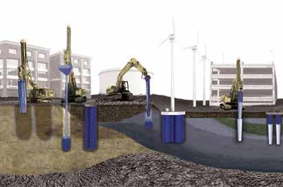
Give your structure stability
Work with Geopier’s geotechnical engineers to solve your ground improvement challenges. Submit your project specifications to receive a customized feasibility assessment and preliminary cost estimate at geopier.com/feasibilityrequest.
800-371-7470 geopier.com info@geopier.com
©2016 Geopier Foundation Company, Inc. The Geopier® technology and brand names are protected under U.S. patents and trademarks listed at www.geopier.com/patents and other trademark applications and patents pending. Other foreign patents, patent applications, trademark registrations, and trademark applications also exist.
Roebling wrote a long final report to the Trustees of the bridge, dated April 1, 1867, in which he not only described the bridge he built but why he built it the way he did. All civil engineers and engineering students should read this report, so they learn the conditions under which Roebling and Charles Ellet worked just before and after the civil war. Excerpts from the report include:
Thus united by strong cords of wire, we all fervently hope, for the sake of a common country, that these two great commonwealths will forever continue to use this national highway as a perpetual link of mutual interests and amicable relations, commercially, as well as socially and politically.
To comply with this act, the distance from center to center of towers measures 1,057 feet, which leaves a clear space of 1,005 feet between the bases of masonry.
The two small spans left open between the abutments and towers are each 281 feet from face to center of tower… As the bridge stands now, its elevation is 103 feet in the clear at a medium temperature of 60 degrees, rising one foot by extreme cold and sinking one foot below this mark in extreme heat. [On the towers, Roebling wrote:]
It is a difficult task to produce a proper architectural effect when designing towers for a suspension bridge of large dimensions. Highly ornamented masonry may be built, but it looks out of place, when the general impression should be that of simplicity, massiveness and strength. On the other hand, a public work, which forms a conspicuous landmark across a great river which separates two large cities, both abounding in highly ornamental facades, should also serve as a model of appropriate architectural proportions. Public works should educate public taste; at any rate, should not violate it. In the erection of public edifices, therefore, some expense may and ought to be incurred in order to satisfy the artistical aspirations of a young and growing community. [On the anchorage chains and cables:]
Each chain is composed of 9 links, of an aggregate length of 92 feet. The lower links consist of 14 and 15 bars, alternately, each bar 10 feet long from center to center of eye, 9 inches wide and 1½ inches thick, making a solid section of 12 square inches.
The eighth and ninth links are formed of 17 bars, with an aggregate section of 190 square inches, while the lowest link has a section of only 168 square inches…
The bridge floor is suspended to two cables. Each cable is composed of 5,180 wires, No. 9 gauge, and forms a cylinder of
12½ inches in diameter. Eighteen feet of this wire weigh one pound, and 60 wires have an aggregate metal section of one square inch. The deflection of the cables is 89 feet at a medium temperature…The cables of the Ohio bridge are wrapped from end to end with No. 10 wire. [On the subject of suspending:]
Except one hundred in the center of the main span, they are all made of wire rope.
To obtain more stiffness the short ones in the center are made of solid rods 1¾ inches diameter. The rope suspenders are 5 inches circumference [1.6-inch diameter], equivalent to 45 tons ultimate strength.
Those next to the towers are greatly relieved by the action of the stays, and consequently reduced to 36 tons strength. [On the deck system:]
The total width of the floor is 36 feet between the outside railings. The cables are suspended between the roadway and sidewalks, and they form, therefore, together with the suspenders and stays, division lines. Inside of the suspenders two lines of iron trusses 14 feet high, extend over the whole length of the bridge from abutment to abutment... Every 5 feet, corresponding to the suspenders, iron beams, 39 feet long are attached to the latter. These beams are made of two pieces, spliced in the center; their section is of the usual beam pattern, 7 inches deep, weighing 20 lb. per foot lineal… Under the roadway, each beam is further strengthened by truss rods, which pass under the center girders… [On stays:]
The general plan which I have always pursued in my works insures, by the heavy contraction of the cables in the center of the span, great lateral stability at this point. The larger and heavier the span, the greater will be its comparative stability at the center… Aside from simply stiffening the floor, the stays are rendering another and very important service; they effectually insure equilibrium between the main and half spans.
Without the stays and trusses, the elevation of the bridge floor would be too light in appearance, as compared to the massiveness of the towers. As it is, the whole has a pleasing effect, and at the same time presents strong and reassuring proportions, which inspire confidence in the stability of the work.
Where the cables enter the towers on the river side, 19 wire ropes, each 2¼ inches diameter, will be noticed descending in straight lines to different points in the floor. Crossing the suspenders diagonally,
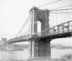
Bridge after rehab in 1896, note sidewalks wrapping around the towers.
the two are connected by wire wrappings, which keep them firmly in their position.
Thus a network is formed that occupies the same inclined plane, which coincides with that of the cables. The total number of stays in the main span is 76. [On decking:]
The roadway for vehicles is divided into two tracks, which compels wagons to keep to the right, and to follow each other in succession. By this arrangement all confusion and turning out is avoided, and more teams can be passed than would otherwise be possible. The bridge opened for pedestrian traffic in November 1866. The official opening was held on January 1, 1867, even though finishing up work went on for another six months. Its total cost was $1,491,110, making it the most expensive bridge built in the United States at the time. What Roebling had done was build a 1,057-foot long suspension bridge taking the record from Ellet’s Wheeling Bridge at 1,010 feet. It would remain the longest bridge until the Brooklyn Bridge opened in 1883, with its span of 1595 feet 6 inches. Between 1895 and 1899, Wilhelm Hildenbrand, John A. Roebling’s assistant in the preliminary plans for the Brooklyn Bridge and Washington A. Roebling’s assistant on the final plans and construction of the Brooklyn Bridge, added two 10½-inch diameter cables and anchorages while widening and replacing the suspended structure without stopping traffic. Tolls were removed in 1963 after the Commonwealth of Kentucky purchased the bridge in 1962. Kentucky purchased it as the state line ran to the northerly bank of the Ohio making most of the bridge in Kentucky. In 1982, the bridge was officially named the John A. Roebling Bridge. A statue of Roebling was placed in a park in 1988 on the Covington side, with Roebling holding a ruler in his left hand with plans laying on a rock at his feet. It was named a National Historic Civil Engineering Landmark in 1982 and added to the National Register of Historic Places in 1975.▪

Business Strong for Seismic Companies
New Products and Services Help SEs Do More For Less


By Larry Kahaner
At RISA Technologies (www.risa.com), Amber Freund, Vice President, Operations, is seeing slow and steady growth since coming out of the recession. From that time, she says, a lot of small engineering startups have popped up, and most have been turning to RISA for their structural analysis needs. RISA has responded, in part, by adding a powerful time history analysis capability to the latest version of RISA-3D. “Simply put, this is the ability to load and analyze structures as a function of time. Th e primary application of this feature was intended for the analysis of vibrating equipment on steel/concrete frames, but we have also seen users utilize time history for other applications, including wind and seismic.” Freund says that in a recent project, one of their users had his proprietary structure analyzed in a wind tunnel which produced plots of defl ection versus time for a number of nodes on the structure. “Th e user was then able to import that data into RISA-3D to essentially ‘shake’ the structure exactly as it had been shaken in the wind tunnel. RISA-3D was then able to back out the forces and stresses caused by the shaking. Th is type of analysis allowed the user to identify stresses in parts of the structure where strain gauges had not been placed during testing.” As for trends, Freund has noticed the high frequency of new codes being released and the increasing complexity of those codes. “For example, by the time we got the 2011 Masonry Code implemented in our software, the 2013 Masonry Code was already being published. We have worked hard to get ahead of the curve so that new codes are already in the program by the time they are adopted by the states, but it is almost a full-time job for us. Th e complexity of the new codes is also unprecedented. For example, if you follow the ASCE-7 and AISC codes to the letter, it is virtually impossible to satisfy them with hand calculations. As a staff of mostly professional engineers, we at RISA sympathize with the engineer on the ground who is trying to comprehend all of this. Th at is why we provide transparency in our software and educational webinars on the ever-evolving nature of the design codes,” she says. (See ad on page 76.) Frank Metelmann, President of Decon (www.deconusa.com), a Jordahl Company, would like SEs to know about their two product groups. “We have stud rails which provide punching shear reinforcement, and then we have Jordahl anchor channels, which are used to connect high loads and concrete wherever you cannot drill into the concrete. As for new products – it is more software-related. We have a new software that calculates the design of the anchor channels and also for the stud rails.” He says the software is a tool being off ered to customers to make it easier for them to design and calculate the loads that can be used with their product. He adds: “For the anchor channels, we have an ICC report and evaluation report which we just received last month.” How’s business? “Business is doing well. We have full order books for the next year or two,” says Metelmann. “Th e [U.S] elections coming up can always throw a wrench into the system, and that is one concern we have, but everything looks positive up to now.” Sideplate (www.sideplate.com) has been growing at about 25 to 30 percent per year, says Jason Hoover, Eastern Regional Business Manager, Industry Outreach Executive. “Th is year started a little slowly, particularly in the eastern U.S., but we’ve been picking up some momentum recently and are on pace to hit a similar target. SidePlate has been in business for almost 22 years, and we still have a lot of growth opportunities. In fact, we are currently looking to hire structural engineers in California and the middle of the U.S.” Hoover notes: “Th e SidePlate Bolted SMF [Special Moment Frame] is our latest innovation, which is applicable for high-seismic projects. We completed the full-scale testing earlier this year, and this bolted connection performed better than our fi llet-welded connection ever did. In general, the SidePlate stiff ness controls frame drifts better than any other connection, but the biggest advantage of our fi eld-bolted connection is the speed of construction. It simply drops in place and gets bolted, so there is no fi eld welding at all. Our motivation is always to make structures more effi cient, from design through construction. We’ve consistently heard that welding is expensive and slow, and welders are diffi cult to fi nd. Developing a fi eld-bolted option was a natural progression for SidePlate.” He adds: “We continue to see structural engineers asked to do more for less. Design schedules are shorter and expectations are higher, but the fees are not following suit. I do not know the answer to this, but SidePlate has over 20 engineers, and we design well over 100 steel buildings each year. Accordingly, SidePlate’s assistance takes some of the burdens off of the structural engineer of record, and we do this at no charge to them.” Hoover says that there is a perception that SidePlate is only for seismic projects. “We still fi ght this consistently. Frame stiff ness matters in ‘wind world’ also, and much of our recent growth has been from wind-governed jobs where SidePlate designs save money versus conventional steel frames. I’d also like SEs to keep an open mind and acknowledge that, while we have a new way of doing things, we are partners with them. We do not have anything to sell them as our fees are paid by the construction team, and we can help make their lives easier.” (See ad on page 57.) Says Rich Madden, Marketing Director at New Millennium (www.newmill.com), “To optimize building design and safety, FlexJoist tension-controlled open web steel joists are engineered to exceed standard steel joist design for strength, reliability and ductility. Th is alternative design approach gives building owners and specifi ers the option of consistently higher steel joist performance at an aff ordable cost. Increased strength, higher reliability index, and improved ductility provide an enhanced timeframe for emergency management in the case of an overload situation. Th e Flex-Joist system can be coupled with a third party overload sensoring system to enhance building safety further.” Madden continues: “A Flex-Joist project is ideally suited for the optional, post-erection installation of electronic sensors by a thirdparty provider. In the event of an overload, the bottom chord and end webs of a Flex-Joist will be highly stressed prior to collapse. Sensors and alarms installed along these components by the third-party provider can establish an early warning system for possible overload removal, roof shoring, and evacuation of personnel.” He adds a disclaimer that “no joist will withstand sudden and catastrophic impact forces that
exceed system capability. Flex-Joist design offers the probability of high ductility and time delay under static gravity overload conditions.” Says Madden: “The open web steel joist industry produces millions of joists each year that safely support roofs and floors in hundreds of thousands of buildings. Due to the range of potential overload condition, including unusual snow and rain levels, it is inevitable that some percentage of roofs and floors will be overloaded beyond anticipated worst-case load conditions during the lives of these structures. The FlexJoist Gravity Overload Safety System offers a safety feature to building owners and managers seeking additional protection against potential overload conditions and related risks of damage, injury and exposure to liability. Under most overload conditions, Flex-Joist introduces important advantages including engineered overload safety for floors and roofs, a steel joist structure designed to flex under extreme static gravity overloading, a time delay for possible evacuation and injury prevention, and possible shoring, removal and collapse prevention.” Emory Montague, Director of Engineering at Simpson StrongTie (www.strongtie.com), suggests that with the increase in urban light-rail infrastructure and a younger demographic of environmentally-conscious consumers, there is an increase in dense urban infill rental units under construction nationwide. “This trend is expected to be steady or increase over the next ten years. Some cities are also looking at ways to make their communities more resilient, giving them the ability to bounce back quicker after a natural disaster. This push for better performing structures has increased the focus on providing more robust connections to create a continuous load path, tying the structure together from the roof to the foundation. These multi-story structures have demanded new solutions, where the continuous rod and screw systems have gained wider acceptance over the last five years because of their relative low labor costs,” he says. To help meet these and other challenges, Simpson Strong-Tie recently released the Strong-Rod Systems Seismic and Wind Restraint Systems Guide (F-L-SRS15). Says Montague: “the guide provides insight into a variety of special design considerations when using continuous rod systems for shearwall overturning restraint. It also outlines how to take advantage of working with us as your full-solution design partner. By contacting Simpson Strong-Tie early in your project and sharing specific design loads and structure geometry, we can collaborate to create the most cost-effective and project specific solution for shearwall overturning restraint using the Strong-Rod Anchor Tiedown System (ATS).” Montague says that one reason they offer this service is because Simpson Strong-Tie is constantly innovating to find better products that make installations faster, save cost, or provide additional benefits to their customers. “One of the main considerations to address when using continuous rod systems in multi-story, light-frame construction is wood shrinkage. Take-up devices are used to keep the rod system components tight and ready to function in an earthquake or storm after the wood framing has settled. We offer several styles of take-up devices to suit the application and load requirements. Recently, we extended our ratcheting take-up device (RTUD) line of products from sizes that accept 3/8-inch and ½-inch diameter threaded rod to include the RTUD5 for 5/8-inch and RTUD6 for ¾-inch diameter rods. The RTUD is extremely cost effective, code listed (ESR-2320) and allows for unlimited shrinkage compensation.” Business is strong, concludes Montague. “With our new, more streamlined rod system assemblies and lower costs to the installer, we have seen a significant increase in Strong-Rod Systems sales in 2016. Our innovative truss and floor-to-floor screws are also gaining popularity in high-wind areas.” (See ads on page 17 & 31).▪
ADVERTISEMENT–For Advertiser Information, visit www.STRUCTUREmag.org
www.newmill.com/7

We’re building a better steel experience
Our collaborative approach will help you achieve the architectural vision while optimizing construction related costs. New Millennium is your nationwide resource for the broadest range of custom-engineered steel products and systems. We can support you with our industry-leading BIM-based joist and deck design, backed by a dynamic manufacturing and delivery process.


