
34 minute read
Historic Structures
significant structures of the past
Trenton Bridge
First Bridge across the Delaware River
By Frank Griggs, Jr., Dist. M. ASCE, D. Eng., P.E., P.L.S.
Dr. Griggs specializes in the restoration of historic bridges, having restored many 19th Century cast and wrought iron bridges. He was formerly Director of Historic Bridge Programs for Clough, Harbour & Associates LLP in Albany, NY, and is now an independent Consulting Engineer. Dr. Griggs can be reached at fgriggs@nycap.rr.com.
Trenton Bridge looking easterly from Pennsylvania.
Theodore Burr had just finished his Union Bridge in Waterford, NY (STRUCTURE, February 2014) when he was called to Trenton, New Jersey to build a toll bridge across the Delaware River just above the falls. The New Jersey Legislature passed an act for a bridge on March 3, 1798 and the Commonwealth of Pennsylvania passed a similar law on April 4, 1798, entitled “An Act to authorize the Governor of this Commonwealth to incorporate a company for erecting a Bridge over the River Delaware at or near Trenton.” There was a high degree of risk involved in building a bridge over a major river that was noted for flooding and ice jams. This made it difficult to sell shares in the bridge company and sufficient funds were not raised to start construction until May 21, 1804 when the cornerstone was placed. Burr was given charge of designing and building a five span bridge over the Delaware River between then Trent’s Town (now Trenton) New Jersey, and Morrisville, Pennsylvania, thus making it an interstate bridge. He designed a variation of a tied arch with iron verticals and a large upper wooden chord made of laminated planking. His iron verticals were suspender chains similar to those used by James Finley in his suspension bridges of the time, in that they were a series of loops. The wrought iron loops were forged together into a chain to arrive at the proper length, inserted through the wooden upper chord and held with a pin. Where did Burr get the idea for a tied arch in wood? Did he see his arch as a Finley Suspension Bridge reversed, or did he follow the statement of Thomas Young that “as the flexible chord hangs, so does inverted the rigid arch stand?” Did he know of a British patent #2,109 issued to James Jordan on May 24, 1796? Jordan claimed he could suspend “canal troughs or roadways from laminated wood or iron arches, the end connections to be so arranged that there was no thrust on the abutments.” Whatever the source, Burr designed and built a bridge that was unique to the United States, and one that was noted around the western world. During construction, which began on May 21, 1804, the company built the piers and abutments to a height they thought was well beyond any height the Delaware River could reach. After completing the stonework, but before the wooden superstructure was begun, the Delaware rose to a height that covered the newly placed piers and abutments. The contractor immediately raised the stonework above the highest water just experienced. James Mease’s Geological Account of the United States published in 1807 noted “The bridge at Trenton, over the Delaware River, thirty miles above Philadelphia, justly claims distinguished notice in the present work. It is to be regretted that the ingenious architect, Mr. Burr, had not given to the public a detailed account of a work of such great and general utility, the execution of which does him so much honour.” He wrote,
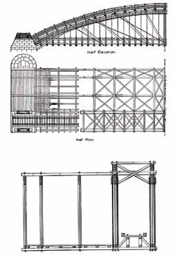
“The superstructure of the bridge consisted of five wooden arches, respectively 203, 198, 161, 186 and 203 feet in the clear, each composed of five great arched ribs rising from the chord in the proportion of 13 feet to 100. These ribs were made of four-inch pine planks, a foot wide and from 35 to 50 feet long, built up into a thick, laminated rib, three feet wide [deep]. The relative placing of these ribs left two openings of 11 feet each in the center of the bridge for carriage ways, and two more, each 4 feet 6 inches wide on the sides for footwalks. The ribs were spaced and bound together on the top circumference of the arches by ties and diagonal braces, fastened to the ribs by bolts and screws at intervals of 8 feet. The floor was suspended from the ties by perpendicular iron rods, securely fastened in the wood. Wing arches and diagonal braces were effectively used throughout to eliminate all motion between the parts of the bridge, thus making it a rigid and solid structure.
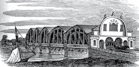

Early illustration of Trenton Bridge arches/roof and Pennsylvania Portal.
Th e entire bridge was covered by a roof of cedar shingles, and was enclosed at each end. Originally there were high and elaborate fronts, both on the New Jersey and the Pennsylvania ends of the bridge, with great arched doorways over the carriageways and footwalks. Balustrades four feet high ran along the whole length of the bridge, outside of the footwalks, to protect the pedestrians.
Th e bridge rested upon the abutments and four piers, all of stone. Th e piers were made about one-fourth higher than they had originally been planned…
Th e ends of the piers upstream were semicircular and, after rising fi ve feet, gradually receded to the top, where they were fi nished off in a half-dome. Th ese piers were 62 feet long and 20 feet deep.” Herman Haupt, in his 1851 book on Bridge Construction, wrote that the diagonals were inserted and anchored into cast iron shoes at the lower end, and tied to the upper arches with iron straps acting as counter braces [ties]. Th ey were twin 6 x 10-inch timbers, spiked to the lower chord and secured to the arches by long 2-inch by ½-inch iron straps… and indicated the links of the suspenders were of 1⅛ -inch square bars, about 4 feet long and 5 inches wide, passing fl atways through the arches and between the chords and counter braces; a key passing through the link on the top of the arch. Th e lower chord was made of a pair of 6½ x 13½ -inch timbers and, again according to Haupt, “are connected by means of long straps of iron passing around the end of the arch at the skew-back, and bolted through the chords.” Haupt also described what he called spur arches, noting: “On the sides are large spur arches of the same dimensions of the main arch of the truss, extending from a point 8 feet outside of the truss on the abutments and piers, and terminating within 44 feet of the centre-spiked at the point of intersection of the arches of the main truss.” In summary, the arches were supported by a combination of the diagonal ties, tension chords and bearing on the piers and abutments. Mease continued his write up of the bridge by stating, “the three great objects, convenience of travelling, strength, and durability, are all happily united in the model adopted...nor has ornament been wholly thrown aside. Th e access to the Bridge, on either side, and throughout the whole extent of the platform, presents to the traveller a plane, without any sensible rising.” Mease fi nished his report on the bridge with:
Our bridge, we are assured by Mr. Burr, combines double the strength of either [Waterford or Fort Miller] of them; but what constitutes the greatest excellence of the Delaware bridge, is the prospect of its durability… the permanency of the stone work is not to be questioned, and by the proposed covering, the stamina, or main parts of the wooden superstructure, will be eff ectually protected from decay by the wet, while those parts we exposed to injury from the weather, are all susceptible of the most complete repair. Th e entire structure was roofed shortly after construction. Instead of the standard gabled roof running along the axis of the bridge, Burr used a conventional gable over his piers with a gabled roof running transversely over his arches. Th e only walls that were covered were over the piers, leaving the arches exposed on the side. Th e primary reason he did not cover his walls and have the normal gable roof over his arches, besides cost, was the large wind loads that would have made if diffi cult, if not impossible, to brace the arches. Th e bridge was opened on January 30, 1806 to a large celebration that was described in the United States Gazette on February 5, 1806:
On Th ursday the 30 th ult. the bridge over the Delaware River near this place was
Triple Protection Against Corrosion
Increase Corrosion Resistance
Use in areas susceptible to corrosion and chloride
Prevent unsightly appearance to concrete
Increase the life expectancy of metals, steel and rebar
Repel Water
Reduce Chloride Permeability
Add Corrosion Inhibitor to Cement All® , Mortar Mix, Concrete Mix and DOT Repair Mix for triple protection against corrosion
800-929-3030 ctscement.com
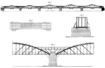
Stevenson drawing of Trenton Bridge. Picture looking at southerly side of bridge with reinforced arches for railroad, beginning of iron truss bridge on left.

opened to the public. The collection of people assembled on this pleasing occasion was great. A procession was formed, commencing at the house of Amos Howell, from whence they set out at 12 o’clock. Burr and his workmen led the parade across the bridge, while 17 cannons [one for each state in the Union] at each end of the bridge fired throughout the procession. Once across the bridge, the entire procession switched from foot to carriages and came back across the bridge in the same order. When they returned, a ceremony was held primarily to honor Burr and his men. The President of the bridge company made the following address:
To you sir, as their principal architect, great commendation is due, for the fidelity, zeal, and unremitted industry, you have manifested in the superintendance and judicious management of this important and arduous undertaking; being your self equally expert to work in stone and in iron as in wood, you have given a direction and energy to each of those branches which tended greatly to facilitate their progress.
The skill and ingenuity discovered in the design and plan of our bridge, has already been the subject of high encomium by a discerning public, as well as by the Board; and it now only remains for them to testify their entire approbation of the masterly stile in which the workmanship in every part appears to be executed, but as it regards neatness and strength, to those who are judges of architecture the simplicity and justness of the plan of our Bridge, and the order and symmetry of its structure, cannot fail to be highly appreciated, while to those artists in the science of
Bridge building, it must prove a valuable model and worthy of future imitation… At a reception Abraham Hunt made another toast to Burr as follows:
Theodore Burr – may the Trenton
Delaware Bridge prove as useful to the publick, as the simplicity and strength of the plan, and the skill and ingenuity displayed in the workmanship thereof, will reflect credit on its Chief Architect. David Stevenson, a noted British Engineer, visited the bridge about 30 years after its opening and obtained a copy of the drawings. He reproduced them in his 1838 Sketch of the Civil Engineering of North America, Comprising remarks on the harbours, river and lake navigation…and other works in that country. He gave a detailed description of the bridge and brought the design to an audience in England, but there is no evidence that anyone in England picked up on this design. In 1835, rails were laid on the north wagon road, and trains, generally hauled by horses, crossed the river. This required the southerly carriageway to handle two-way traffic on a width that was inadequate. In the summer of 1848, a decision was made to widen the bridge to accommodate two-way carriage traffic, one sidewalk and one railroad track. To handle this additional traffic, they simply removed the roof, all overhead bracing and the deck structure between the two southerly most arches. Then they moved the southerly arch five feet south on the existing piers that were wide enough to accommodate this shift. They strengthened the two southerly arches by placing additional arches of planking over them and bound the new arches to the old with short ties. After the arches were strengthened, they placed new overhead bracing to stabilize them. In the great Delaware River flood of 1841, only Timothy Palmer’s Easton Bridge, opened in 1806, and Burr’s Trenton Bridge survived. A steel bridge was built on the enlarged piers for the Pennsylvania Railroad in 1892. In 1898, another parallel steel railroad span was built on expanded piers, making a total of three lines of trusses on the same piers. The two railroad spans were removed in 1903 when an adjacent concrete arch bridge for the railroad was built. The current vehicular bridge, called the Lower Trenton Bridge, was built in 1928 on Burr’s piers and is illuminated with a sign stating, Trenton Makes the World Takes. Burr went on to build many bridges across the Mohawk, Susquehanna and other rivers. All of these, however, were similar to his Waterford Union Bridge. He never used the Trenton Bridge design in the future, even though it was a success.▪





the TRanSfoRMaTion of the HiSToRiC fiRST naTional
STaTE Bank BUilding
Newark New Jersey – Part 2
By D. Matthew Stuart, P.E., S.E., F.ASCE, F.SEI, SECB, MgtEng and Ed D. Cahan, P.E., S.E.
Pennoni’s involvement with the adaptive reuse of an existing historic building included the development of several innovative structural solutions. Part 1 of this article (February 2014) provided a history of the building and the initial major renovation challenges (Figure 1). This article will discuss life safety improvements and enhancements to utilization of the 12th floor and roof spaces. Improvements in life safety codes since the original construction of this mid-rise building meant that the existing egress paths through the structure were no longer adequate to support the use of the structure as a hotel. In order to rectify this, the project added 800 square feet of floor space to each floor, containing a new stair and elevator. Accessing this new 9-story tower required demolishing a large portion of the existing east exterior wall. Supporting it presented significant structural challenges, because the footprint of the addition was located directly above the existing low-rise building but did not match its column grid. Pennoni presented two alternatives. The first consisted of vertical diagonal braces supporting the floor beams of the addition from the existing east exterior columns, such that each level of the new tower was essentially “corbeled” from the mid-rise tower. The second option consisted of new columns at the east face of the addition that would be supported by significantly reinforcing the existing beams of the existing low-rise roof to act as transfer girders. Ultimately, the design team chose the latter due to architectural restrictions in the geometry and location of the diagonal braces proposed by the first option. After establishing the support scheme for the stair and elevator addition, Pennoni concentrated on evaluating the impact of the new addition on the existing structure. First, the double spandrel beams were analyzed for the loads imposed by the reaction of the new adjacent framing.

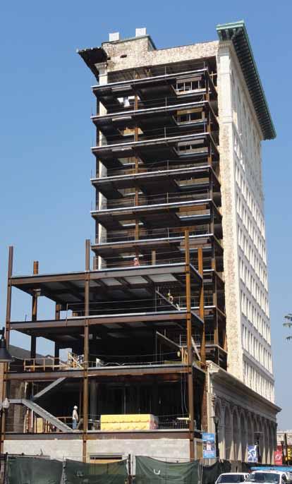
Figure 1: Partially erected stair and addition framing.
Because the outer beam was primarily designed to support only the east exterior brick cladding that was being removed to allow for the addition, it was able to support the new beams of the stair tower without the need for reinforcement (Figure 2). Furthermore, the new net reaction at the columns supporting the outer beam of the double spandrel was approximately the same as the original condition. Transferring the lateral load of the stair tower addition into the lateral-load-resisting system of the existing mid-rise structure involved drilling horizontal epoxy dowels into the existing concrete slab at each level. Additionally, placing continuous reinforcing steel at the north and south ends of the addition, and doweling it into the adjacent existing concrete slab, created diaphragm chord members in the new slab. It was also necessary to investigate the distribution of new lateral forces created by expanding the sail area and square footage of the structure as a result of the additions. The lateral load resisting system of the existing structure had sufficient capacity to support these loads based on the exception allowed by the International Existing Building Code (IEBC) when the increase is no more than 10% over the original. The lateral resisting system used in the First National State Bank Building involved angle bracket kicker braces, encased in concrete, that attached the girders and columns together to form rigid moment frame connections at a number of locations throughout the
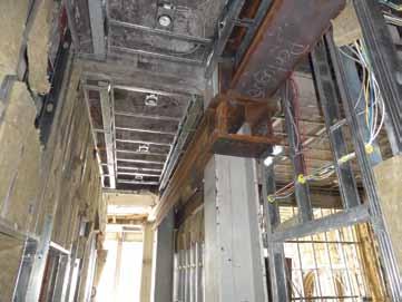
Figure 3: New transfer girder connection at existing column.
building. This type of system was first used in the Reliance Building in Chicago in the mid-1890s. The final structural engineering task for the stair and elevator addition involved reinforcing the existing third floor beams of the low-rise that were to support the new columns above by adding transverse stiffeners beneath the new column flanges. These stiffeners also transferred the new concentrated column base reactions to new transfer girders built tight to the bottom flange of the existing beams. The transfer girders are designed to support the entire column reaction, which allows the existing beam to transfer the load through the stiffeners to the new beams below and still function as a part of the existing third floor framing. The top flange of the transfer girder was welded to the bottom flange of the existing beam to enable the transfer of any horizontal shear flow between the two members. The increased reactions where the transfer girders connect to the existing columns required stiffened seat connections to strengthen the existing conditions (Figure 3). Welding HSS sections to the column flanges increased the weak-axis bending capacity of the column section to handle the resulting eccentricity. Transforming the existing roof of the mid-rise building into an occupied terrace with outdoor dining required reinforcing the structure to support the new loads. While the existing drawings showed the steel framing, they provided no concrete slab information such as compressive strength or thickness. They also showed no roof sections, and it was suspected that the slope that existed for proper drainage involved a concrete topping slab in addition to the main roof slab. Roof cores at suspected high and low points enabled determination of the slab composition and physical properties, confirming Pennoni’s suspicions. This meant that it would be possible to use the existing slab in conjunction with new steel channel shear connectors on top of the existing beams to create composite action with the primary roof girders, thereby increasing their structural capacity. The existing roof beams spanning between girders would be overstressed as a result of the heavier loading associated with the new terrace. In order to prevent this, new steel roof beams were added between the existing ones in order to decrease the tributary width (Figure 4). The higher yield strength of the existing steel was taken into consideration, determined via coupon tests, as opposed to the strength provided by historical databases. An alternate method to reinforce the roof structure was to weld steel split T or WT sections to the underside of the existing beams and girders. However, this method was not used because of the excessive demolition that would have been required in order to remove a portion of the concrete encasement that provided fire protection for the existing beams.
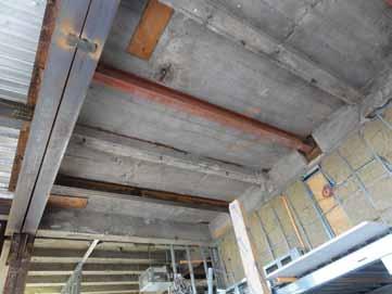
Figure 4: Existing beam and slab strengthening.
Completing the renovation design required solving several other challenges, which included green initiatives to conserve energy via the introduction of a solar panel array along the top of the existing roof’s copper cornice. The outrigger support structure did not have sufficient capacity; therefore, a new structural frame was designed to cantilever over and above the existing cornice roof, by connecting to the exterior column extensions located within the existing parapet. In addition, two new energy recovery units (ERUs) were required in order to provide conditioned air efficiently throughout the structure. However, the large size and weight of the ERUs made it difficult to find acceptable locations for their placement. The higher existing floor-to-roof height at the 12th floor made this location an attractive option. In order to limit the resulting loss of floor space, the units were stacked by providing a new steel dunnage frame supported by the existing floor girders at the lower ERU, and a new steel frame that spanned between the existing steel columns at the upper ERU (Figure 5). Taking advantage of the increase in steel yield strength found via coupon tests eliminated the need for reinforcing. The height at the 12th floor also allowed for the construction of luxury suites with lofts constructed of metal floor decks and cold-formed steel walls bearing on the existing floor beams, which were reinforced with new steel split T sections welded to the underside in certain locations where the existing structure was overstressed. Upgrading the vertical transportation systems with machine-roomless custom elevator cabs to fit the existing floor openings also posed
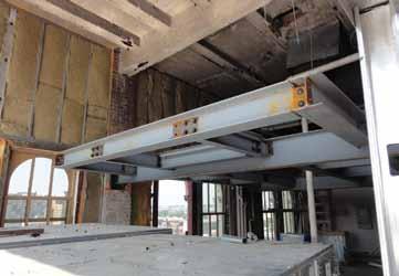
challenges that included supporting the elevator sheave beams and providing the required overhead clearance. Ultimately, this resulted in the need to demolish a portion of the existing elevator penthouse roof structure and design a new one that met the needs of the new elevator manufacturer. The existing roof beams supporting the new penthouse also required strengthening. Upgrading the original fourstory stair and elevator tower located at the rear of the facility involved the complete demolition of the masonry walls and steel framing from the ground floor up, with a new six-story tower taking its place. A 2012 report entitled, The Greenest Building: Quantifying the Environmental Value of Building Reuse, produced by the Preservation Green Lab of the National Trust for Historic Preservation, found that when comparing buildings of similar size and function, environmental savings are almost always found through building reuse, rather than demolition and new construction. Additionally, the article found that reusing existing buildings provides benefits to the surrounding community and local economy. The adaptive reuse of the First National State Bank Building is an exemplary rehabilitation project highlighting these social, economic, and environmental benefits by restoring pride in a historic structure and creating revitalized business in an evolving neighborhood, all while decreasing the overall carbon footprint (Figure 6). This transformation would not have been possible without creative, yet simple and constructible, structural engineering solutions for the complex renovation changes.▪ D. Matthew Stuart, P.E., S.E., F.ASCE, F.SEI, SECB, MgtEng (MStuart@Pennoni.com), is the Structural Division Manager at Pennoni Associates Inc in Philadelphia, Pennsylvania. Ed D. Cahan, P.E., S.E. (ECahan@Pennoni.com), is a project engineer with Pennoni Associates Inc in Philadelphia, Pennsylvania.

Figure 6: Rendering. Courtesy of DeRosa Group Architects.
adVERTiSEMEnT–for advertiser information, visit www.STRUCTUREmag.org



An Overall Strong Year for Steel Expected, Companies Say

Some Government Projects Cut Back as Commercial Jobs Grows
By Larry Kahaner
Companies in the steel fabrication business are expecting a strong 2014 as firms continue to innovate, improve their existing products and focus on their particular sectors. “We are seeing some strong activity in large commercial construction projects in select metropolitan areas. Th ese are primarily high-rise residential properties,” says Kevin Bates, Vice President Sales & Marketing at MMFX Steel Corporation, (www.mmfx.com) in Irvine, California. “We have seen some slowing in highway and bridge construction recently, but this has really varied state by state in the U.S. States having robust bridge construction markets have put through state level highway funding appropriations versus being highly dependent on federal money. Additionally, states that have some level of acceptance to allow Public-Private Partnerships are seeing good construction activity.” At the Vulcraft/Verco Group (www.nucor.com) in Norfolk, Nebraska, Michael Klug, Marketing Coordinator, New Products and Market Development, notes: “Th e re-shoring of American jobs will surely push our market in the right direction; this is, in large part, due to our domestic energy supply that continues to grow and create an environment that is conducive for manufacturing.” Others, like Bob Allen, U.S. Construction Hardware Product Manager of ITW Building Components Group, (www.itwbcg.com) in Pompano Beach Florida, suggest that companies that have survived the past downturn will do well simply because they have weathered a severe storm and have come out stronger. “Th ey all believe that the worst is behind them. Th ere’s a lot less of them to meet market demand, so from that standpoint, I feel the ones that survived are going to be in good shape.” Allen notes that his company will be introducing a series of face mount hangars within the next 30 days. “It’s a new series for us, one that will serve as a replacement for up to four diff erent series that our competitors currently off er.” He adds: “Th at, by itself, will be a huge advantage. Th e load carrying capacity of these face
mount hangars will be the highest in the industry… It fulfi lls a need that is one of the most sought after among our core customers.” (See ad on page 46.) Klug says that his company is always looking for ways to take care of its customers which range from steel fabricators, to GC’s, to erectors, to large corporations and private owners. “Being a part of Nucor Corporation gives us an unmatched supply chain, as well as a wide variety of other steel products that we can off er.” He adds: “We work closely with Tekla, SDS/2 and Revit to ensure that we are leading the industry in the use of BIM.” MMFX’s Bates says that his company has just introduced its ChromX4100 Grade 100 reinforcing steel. “Th is high-strength steel, meeting all of the mechanical properties of ASTM A1035, is targeted at applications that can benefi t from using less reinforcing steel.” He adds: “Th e ChromX4100 complements our other product, MMFX2, which provides uncoated corrosion resistance along with the Grade 100 high strength properties. Th e chemistry of the ChromX4100 has been modifi ed slightly from the MMFX2 to lower the corrosion resistance and as a result lowering its production costs. Th is makes the ChromX4100 rebar ideal for applications needing the higher strength but not requiring the same level of corrosion resistance.” As far as trends are concerned, Bates sees reinforced concrete structures starting to increase the use of high strength reinforcing steels. “As designs are requiring more steel, buildings are getting taller. Th e natural evolution is towards taking advantage of higher strengths. Grade 75 steel is seeing increased use. MMFX Steel has been off ering Grade 100 steel for 12 years and are now seeing its
use pick up since the recent changes to construction codes. We see a future that will move toward even higher strengths when combined with higher strength concrete mixes.” Jason Hoover, Industry Outreach Executive for SidePlate Systems, Inc., (www.sideplate.com) who works out of Strongville, Ohio, says that the company in 2013 debuted a new SidePlate Bolted moment connection option for R=3 projects. “For projects with higher seismic criteria, SidePlate connections are now listed as prequalifi ed moment connections in Supplement #2 of the AISC 358-10 standard.” Hoover says that SE’s will appreciate its features. “Th e SidePlate Bolted connection delivers the same stiff ness benefi ts as our fi llet-welded connection, but the bolted option has no fi eld welding at all so it’s even easier to erect. As of today, we only have a few data points for actual completed bolted projects, but responses from fabricators and erectors have been extremely positive support of the time and money saved at each stage.” He adds: “On the seismic side, the SidePlate connection’s prequalifi cations from other agencies predate the original AISC 358 standard, but we recently decided to go through the eff ort of getting AISC’s thirdparty approval as well. We’re happy to say that their committee reviewed and approved of all of our testing data and results. Th e new Supplement #2 to AISC 358-10 also includes an extensive commentary on the history and evolution of SidePlate connections that will be helpful for engineers looking for more background.” Hoover says that SidePlate’s business is doing very well, and it’s growing. “Our biggest market is healthcare, which has been steady. Th e commercial market seems to be picking up some steam, and “As designs are requiring more steel, buildings are getting taller. Th e natural evolution is towards taking advantage of higher strengths. ... We see a future that will move toward even higher strengths when combined with higher strength concrete mixes.”
while we’ve historically worked on a large number of government projects, those have dried up considerably. Our customers seem to be cautiously optimistic about the near-term general construction forecast, and we’ve heard rumblings that the steel mills are warning of longer lead times as a burst of construction activity is expected in mid-2014.” At ITW’s TrusSteel Division, (www.trussteel.com) offi cials report that business has been steadily increasing as the residential construction market improves. Dave Dunbar, National Sales Manager, says: “Cold-formed steel trusses are the ideal solution for pitched roofs requiring non-combustible materials. With improvement in the retail, offi ce and hospitality sectors, we are projecting continued growth. Two core sectors for our type of construction, assisted living and education, will see mixed results based on regional demographics, and government construction is slowing due to reduced government spending.” TrusSteel recently introduced a new chord shape, the TSC300. “Th e TSC300 chord provides all the benefi ts of the TrusSteel continued on page 46

NEW!
ADVERTISEMENT–For Advertiser Information, visit www.STRUCTUREmag.org
TODAY’S HIGH-STRENGTH REBAR
New from MMFX is Grade 100 ChrōmX 4100 rebar. High strength reinforcing steel with the perfect blend of value and benefits for large construction projects.
Solve Rebar Congestion Improve Concrete Placement Lower Rebar Placing Costs Reduce Placing Time Lower Cage Weights Fewer Couplers
Mat Foundations | Shear Walls | Confinement Ties Drilled Shafts | Bridge Piers | Precast Beams
For more information 866.466.7878 | www.mmfx.com
TSC400 chords, but is more cost eff ective because it maximizes the eff ective area. Th is 3-inch tall chord is utilized for mid-span ranges of 35 to 50 feet at both 24-inch on-center and 48-inch oncenter, depending on load conditions,” says Dunbar. Th e TSC300 was the result of collaboration with the company’s customer base. “Th is new chord was identifi ed as an opportunity to help them off er more competitive systems.” (See ad on page 48.) Rich Madden, Marketing Manager at New Millennium Building Systems, (www.newmill.com) in Fort Wayne, Indiana, says that the company focuses on product development that can improve steel project performance and contribute to a range of total-project cost reductions. “Our research in this area has led to the release of our FreeSpan Beams, our expanded specifi cations for special profi le steel joists, and our new Flex-Joist Gravity Overload Safety System.” He adds: “Our FreeSpan line of castellated and cellular beams features either hexagon or circular openings as a result of the castellation process. Th e beam is 50% deeper and up to 40% stronger than the original ‘parent’ beam, without adding any additional weight. So now you have a very effi cient beam that can be exceptionally cost-saving as well as design-enhancing, because you can create wide-open, wide-span designs with fewer and narrower support beams. All the HVAC and electrical can run through the beams, light fl ows through the beams for added night safety, and the beams have a strong aesthetic appeal.” Th is spring, New Millenium will release its updated special profi le joists catalog, which enables both the architect and engineer to design unique roofl ines on their buildings for a reasonable price.
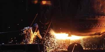
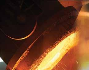
Courtesy of Bradken Inc.
Products include bowstring joists, gable joists, scissor joists, as well as other special shapes. Th e new catalog provides specifi cation tables for over 40,000 possible design combinations. Madden says that Th e Flex-Joist Gravity Overload Safety System addresses a growing concern over unanticipated extreme roof snow and rain loads, which may in some cases be attributable to climate change. “Th e approach is to engineer a steel joist to fl ex much more gradually and deeply than a traditionally engineered steel joist in the event of an extreme overload, so as to establish the element of time delay. With sensors in place to detect this defl ection, an early warning system can signal the need for evacuation, roof shoring or possible removal of the overload.” On the software side of the steel business, companies like Lincoln, Nebraska-based Design Data (www.sds2.com) are continuing to off er new products and services. “SDS/2 2014 is the latest release continued on page 48
ADVERTISEMENT–For Advertiser Information, visit www.STRUCTUREmag.org
of our flagship product, SDS/2 Detailing,” says Michele Arnett, Marketing Manager. “The connection design capability has grown by leaps and bounds in this past version. The SDS/2 Erector is a new product that helps general contractors and erectors plan the job site, and the SDS/2 Approval helps project managers and reviewers to be much more productive.” She says that Design Data’s core customer base is steel fabricators and steel detailers involved in commercial and industrial fabrication, and that list has expanded. “With the recent growth of BIM, the SDS/2 customer base has grown to include designers, general contractors and other segments who benefit from the 3D model.” At RISA Technologies, LLC, (www.risatech.com) in Foothill Ranch, California, Director of Marketing Amber Freund says that RISAConnection v4.0 was recently released. “This new version includes the design of HSS connections, which are a hot topic in the engineering community today.” Freund says of the company’s products, “Unlike more basic connection software that is on the market, RISAConnection designs the connection for all of the applied forces, including axial forces due to beam tension/compression, and flexure on the face of tubes due to shear connection eccentricity.” She adds: “Ever since RISAConnection v1.0 was released, we have received an overwhelming demand to add HSS connection design to the software. The design criteria for HSS is relatively new (by the standards of the engineering community) and many engineers prefer to have reputable software help guide them in application of the latest design practices. By introducing connection design through a RISA product, we hope to educate engineers on the limit states associated with HSS connection design and make them more comfortable with HSS on their everyday projects.” As for business conditions, RISA clients are getting more projects, says Freund. “We are hoping this is a steady trend that continues throughout this year. The industrial sector has remained pretty strong and we are seeing more commercial building projects as well… We are continuing to see BIM being used on projects. Where it used to only be used on larger projects, we are now seeing it used even on smaller projects like curtain walls. The integration between BIM and structural analysis software is important to ensure the accurate exchange of information during the design and construction processes.” (See ad on page 76.) Raoul Karp, Director, Product Management for Bentley Systems, Inc. (www.bentley.com) in Exton, Pennsylvania, sees three major drivers in the industry today: BIM adoption driving increasing structural complexity, tighter schedules requiring closer collaboration and competitive design environment pushing greater productivity. “In 2013 we had a release in each of our major product lines RAM, STAAD and ProStructures. The capabilities of which were squarely focused on addressing these key driving forces,” he says. For the RAM Structural System and RAM Concept, Bentley added several modeling, analysis and reporting productivity improvements including shearwall coupling beam design, code updates and 64bit capability to enable larger more continued on page 50
ADVERTISEMENT–For Advertiser Information, visit www.STRUCTUREmag.org




complex structures and faster analysis. For STAAD.Pro and STAAD Foundation Advanced, they added half a dozen code updates including torsion design for AISC360, productivity enhancements with added advanced capabilities for machine and mat foundations, tension cables and for the fi rst time the ability to run multiple design options of your structure on the cloud and compare and contrast results through your browser. For ProStructures, they expanded the steel modeling and detailing capabilities with advanced rapid stair, handrail and anchor bolt modeling. “We also have expanded our collaboration capabilities with IFC import and export, iModels for collaboration (scheduling, clash detection) with Bentley and non-Bentley products, and added new SolidWorks and updated Revit and Bentley product interoperability with Integrated Structural Modeling,” says Karp. (See ad on page 75.) We are seeing continued innovation in welding and cutting products as well, according to Mark Elender, Senior Vice President North American Sales, ESAB Welding & Cutting Products (www.esabna.com) in Hanover, Pennsylvania. He says: “ESAB has a long history of continuous product improvement and development in delivering high quality, leading-edge equipment and solutions to address the needs of steel fabricators. Our ICE process for Submerged Arc Welding (SAW) is a product of particular interest to structural steel engineers. Th e ICE process can increase a fabricator’s productivity while exceeding the requirements for critical welds. ICE is an elegantly simple technology; instead of adding energy, ICE exploits the excess heat from the Twin SAW
Seattle Tacoma Lacey Portland Eugene Sacramento San Francisco Walnut Creek Los Angeles Long Beach Pasadena Irvine San Diego Boise Phoenix St. Louis Chicago New York
KPFF is an Equal Opportunity Employer www.kpff.com
ADVERTISING OPPORTUNITIES
Be a part of upcoming SPECIAL ADVERTORIALS in 2014.
To discuss advertising opportunities, please contact our ad sales representatives:
CHUCK MINOR
Phone: 847-854-1666
DICK RAILTON
Phone: 951-587-2982
Sales@STRUCTUREmag.org
process to melt an additional non-powered welding electrode. Th is results in double the productivity in deposition rates and in root welds when compared to single wire welding. ICE boosts output signifi cantly without the investment in new welding systems, extra capacity, or additional skilled welding labor.” Adds Elender: “Also of interest to steel fabricators is our new
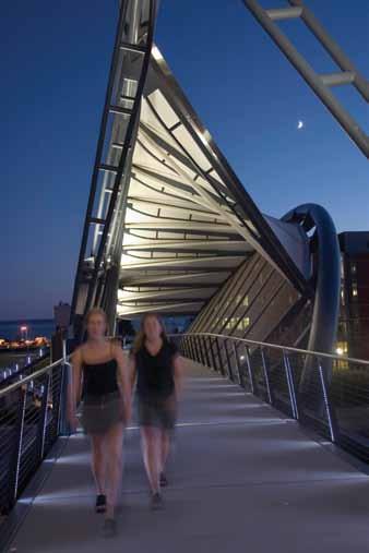
Warrior – a multi-process welding machine capable of delivering up to 500 amps at 60% duty cycle. Warrior off ers users a very good stable arc in multiple processes, including GMAW (MIG), FCAW (Flux-Cored), SMAW (Stick), and GTAW (TIG) welding, as well as HELIX PEDESTRIAN BRIDGE, SEATTLE, WA ACAG (Arc Gouging), and is easy to use and energy effi cient thanks to stateof-the-art inverter technology.” Also new to the company’s Cutting Systems line is the Hydrocut LX waterjet shape cutting machine, a combined waterjet and plasma cutting system. “Th e machine uses a patented combination of thermal and non-thermal processes operating on the same gantry, allowing the machine to cut with the high accuracy of waterjet where needed, but employ the high speed and low cost of plasma whenever possible. Steel fabricators benefi t from the use of both technologies on the same part. High precision contours can be cut with waterjet, while non-critical contours can be cut with plasma,” says Elender. ESAB’s new off erings are developed WINNER OF A from customer input. “We constantly National Council solicit customers’ input to understand of Structural Engineers their requirements and expectations so that we can design and deliver products that help solve their chalAssociations lenges. We are a full line Outstanding integrated supplier, so we Project Award engineer and produce the products we sell.”▪


