18 minute read
Code Updates
Infilling the Frame with Masonry
By Charles J. Tucker, Ph.D., P.E.
As discussed in STRUCTURE® magazine’s February 2012 edition of Just the FAQs, the Building Code Requirements for Masonry Structures (TMS 402-11/ACI 530-11/ASCE 5-11) includes a mandatory language appendix for the design of masonry infills that can be either unreinforced or reinforced using either clay masonry or concrete masonry. Masonry infills can be designed and detailed as part of the lateral force-resisting system (participating infills) or they can be made to only resist out-of-plane loads (non-participating infills). The new appendix of TMS 402 provides the designer with a straightforward method for the design and analysis of masonry infills. Guidelines and consideration are given for both participating infills and non-participating infills, and were developed based on experimental research and performance in the field. Construction of masonry infilled frames is relatively simple. First, the bounding frame is constructed of either reinforced concrete or structural steel. TMS 402 defines the bounding frame as “the columns and upper and lower beams or slabs that surround masonry infill and provide structural support.” After the bounding frame is erected, the masonry infill is constructed in the portal space. This construction sequence allows the roof or floor to be constructed prior to the masonry being laid, allowing for rapid construction of subsequent stories or application of roofing material. All infills (participating and non-participating) require mechanical connectors attached to the bounding frame for support of the masonry against out-of-plane loading. The maximum spacing of the connectors is four feet along the perimeter of the infill. These connectors are not permitted to transfer inplane loads from the bounding frame to the infill. Research shows when connectors transmit in-plane loads they create regions of localized stresses and can cause premature damage to the infill. This damage then reduces the out-of-plane capacity of the infill because arching action is inhibited. The bounding frame must be designed for these out-of-plane loads. In this article, we will discuss masonry infills in greater detail.
In-Plane Shear for Participating Infills
For participating infills, the masonry is either mortared tight to the bounding frame so that the infill receives lateral loads immediately as the frame displaces, or the masonry is built with a gap such that the bounding frame deflects slightly before it bears upon the infill. If the gap is less than 3/8 inches or the calculated displacement, the gap does not conform to the requirements of Code Section B.2.1. However, the infill can still be designed as a participating infill provided the calculated strength and stiffness are reduced by half. The maximum height-to-thickness (h/t) ratio of the participating infill must not exceed 30 in order to maintain stability. The maximum thickness allowed is one-eighth of the infill height. From a code perspective, participating infills must fully infill the bounding frame and have no openings. Code Section B.1.5 does not allow partial infills or infills with openings to be considered as part of the lateral force-resisting system because structures with partial infills have typically not performed well during seismic events. The partial infill attracts additional load to the column due to its increased stiffness; typically, this results in shear failure of the column. The limitation of full panels and no openings may be relaxed as the code matures and more research becomes available. The in-plane design is based on a braced frame model, with the masonry infill serving as an equivalent strut. The width of the strut is determined from Equation 1 (TMS 402 Equation B-1). (See Figure 1 in the February 2012 article.)
w= 0.3
strutcosstrut
where
strut = 4√ Emtnetinf sin2strut 4EbcIbchinf Equation 1
Equation 2
The term strut, developed by Stafford Smith and Carter in the late 60s, is the characteristic stiffness parameter for the infill and provides a measure of the relative stiffness of the frame and the infill. The numerator under the radical includes the modulus of elasticity of the masonry, the net thickness of the masonry, and the angle that the strut makes with the horizontal. The denominator under the radical includes the frame modulus of elasticity, the moment of inertia of the bounding columns, and the height of the infill. Design forces in the equivalent strut are then calculated based on elastic shortening of the compression only strut within the braced frame. The area of the strut used for that analysis is determined by multiplying the strut width from Equation 1 and the specified thickness of the infill. The infill capacity can be limited by shear cracking, compression failure, and flexural cracking. Shear cracking can be divided into cracking along the mortar joints, which includes stepped and horizontal cracks, and diagonal tensile cracking. The compression failure mode consists of either crushing of the masonry in the loaded diagonal corners or failure of the equivalent diagonal strut. The diagonal strut is developed within the panel as a result of diagonal tensile cracking. Flexural cracking failure is rare because separation at the masonry-frame interface usually occurs first; then, the lateral force is resisted by the diagonal strut. As discussed above, the nominal shear capacity is determined as the least of: the capacity infill corner crushing, and the horizontal component of the force in the equivalent strut at a racking displacement of one-inch; or, the smallest nominal shear strength from Code Section 3.2.4, calculated along a bed joint. The displacement limit was found to be a better predictor of infill performance than a drift limit. Generally, the infill strength is reached at lower displacements for stiff bounding columns, while more flexible columns result in the strength being controlled at the one-inch displacement limit. While Code Section 3.2 is for unreinforced masonry, use of equations from that section does not necessarily imply that the infill material must be unreinforced. The equations used in Code Section 3.2 are more clearly related to failure along a bed joint and are therefore more appropriate than equations from Code Section 3.3 for reinforced masonry. The equations used in the code are the result of comparing numerous analytical methods to experimental results. They are strength based.
The experimental results used for comparison were a mixture of steel and reinforced concrete bounding frames with clay and concrete masonry. While some methods presented by various researchers are quite complex, the code equations are relatively simple.
Out-of-Plane Flexure for Participating Infills
The out-of-plane design of participating infills is based on arching of the infill within the frame. As out-of-plane forces are applied to the surface of the infill, a two-way arch develops, provided that the infill is constructed tight to the bounding frame. The code equation models this two-way arching action. As previously mentioned, the maximum thickness allowed for calculation for the out-of-plane capacity is one-eighth of the infill height. Gaps between the bounding frame and the sides or top of the infill reduce the arching mechanism to a one-way arch and are considered by the code equations. Bounding frame members that have different cross sectional properties are allowed by averaging their properties for use in the code equations.
Non-Participating Infills
Because the non-participating infills only support out-of-plane loadings, Code Section B.2.1 requires these infills must have isolation joints at the sides and the top of the infill. These isolation joints must exceed the larger of 3/8 inches or the expected design displacements of the bounding frame, including inelastic deformation due to a seismic event, so that the infill does not receive any lateral loadings. The isolation joints are allowed to contain filler material as long as the compressibility of the material is taken into consideration when sizing the joint. Non-participating infills support out-of-plane loadings according to Code Section B.2.2. As previously noted, mechanical connectors are required for this support. These connectors are not allowed to transmit in-plane loads. The masonry infill may span vertically, horizontally, or both. The masonry design of the non-participating infill is then carried out based on the applicable sections of TMS 402 for reinforced or unreinforced masonry (Code Section 3.2 for unreinforced infill and Code Section 3.3 for reinforced infill using strength design methods). The choice of unreinforced or reinforced masonry belongs to the designer. However, there are seismic conditions which may limit the use to only reinforced masonry. (See the February 2012 article.)
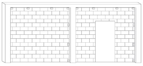
Masonry infills with concrete frame.
Since they support only out-of-plane loads, non-participating infills can be constructed with full panels, partial height panels, or panels with openings. The effects on the bounding frame must be included by the designer.
Examples
The Figure shows a reinforced concrete frame infilled with concrete masonry. Both participating and non-participating infills can be seen in this picture. The infill at the left of the figure is participating due to the fact that the masonry is laid tight to the bounding frame and completely fills the portal space; the mechanical connectors exist but are not visible on the left column. The infill at the right of the figure has a door opening which makes this a non-participating infill. As previously mentioned, each infill’s effect on the bounding beam and columns should be considered in their design or analysis.
Bounding Frame
TMS 402 gives guidance on the design loads applied to the bounding frame members; however, the actual member design is governed by the appropriate material codes and is beyond the scope of TMS 402. The presence of infill within the bounding frame places localized forces at the intersection of the frame members. Code Section B.3.5 helps the designer determine the appropriate augmented loads for designing the bounding frame members. Frame members in bays adjacent to an infill, but not in contact with the infill, should be designed for no less than the forces (shear, moment, and axial) from the equivalent strut frame analysis. The shear and moment applied to the bounding column are not to be less than the results from the equivalent strut frame analysis multiplied by a factor of 1.1. The axial loads are not to be less than the results of that analysis. Additionally, the horizontal component of the force in the equivalent strut is added to the design shear for the bounding column. In a similar manner, the shear and moment applied to the bounding beam or slab are not to be less than the results from the equivalent strut frame analysis multiplied by a factor of 1.1. Likewise, the axial loads are not to be less than the results of that analysis. Additionally, the vertical component of the force in the equivalent strut is added to the design shear. Design of the frame should also take into consideration the volumetric changes in the masonry infill material that may occur over time due to normal temperature and moisture variations. Expansion of clay masonry infill material will exert additional forces on the bounding frame that must be considered. Shrinkage of concrete masonry infill material may open gaps between the infill and the bounding frame that need to be addressed also. Guidance for these volumetric changes is provided in Code Section 1.7.5.
Conclusion
Although masonry infills have been used worldwide for nearly a century, the US structural designer has not had a simple way to take true advantage of their efficiency. The new appendix in TMS 402-11 provides the necessary guidance for the designer to benefit from the inherent lateral strength of masonry infills.▪
Charles J. Tucker, Ph.D., P.E. is an Associate Professor of Engineering at Freed-Hardeman University, Henderson, Tennessee. Dr. Tucker is the Chair of the Masonry Infill subcommittee of the Masonry Standards Joint Committee. He can be reached at ctucker@fhu.edu.




Speci es in seconds, Installs in minutes.
The Strong Frame® ordinary moment frame provides high lateral-force resistance for limited wall space, large openings and soft-story retrofit applications. And since it’s pre-engineered and fabricated, designers can choose the exact frame size in seconds with columns from 8 feet to 35 feet tall and beams from 6 feet to 24 feet wide, as well as two-story solutions. The Strong Frame moment frame is the only frame that’s bolted together, eliminating on-site welding. It also installs in less than an hour and can be delivered to jobsites in just a few days. For steel and wood construction, the Strong Frame moment frame is the time-saving choice. Learn more and view a copy of the Strong Frame Ordinary Moment Frame catalog by visiting www.strongtie.com/strongframe or calling (800) 999-5099.




Tower Stabilization

during Buttress Repairs
By David T. Biggs, P.E., S.E., DistM.ASCE, Hon.TMS


Masonry towers are the focal point of numerous historic buildings and monuments. Th ey grace most religious structures and many signifi cant civil works. Th ese towers present numerous diffi culties for engineers and architects to defi ne the nature of their problems and develop necessary repair interventions. Among the most challenging concerns is structural deterioration of the buttresses and walls. Depending upon where it occurs over the height of the tower, such deterioration produces a weakness that can cause local or global instability of the tower, requiring strengthening as a possible intervention. Th is can vary, from repointing with supplemental reinforcement to in-situ injection with transversal pinning to partial removal and reconstruction. Structural problems with towers can aff ect either the local or global stability of the tower during restoration and strengthening. Caution must be taken on any invasive intervention to avoid further instability of the tower during implementation of the repairs.
Problems
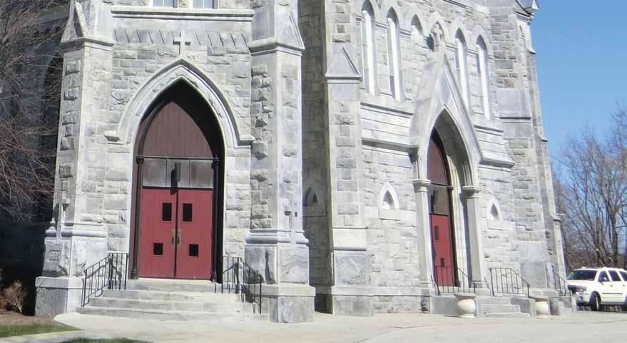
A church in Vermont with an 80-foot-tall tower (Figure 1) was completed in 1892. Th e walls are multi-leaf brick and the exterior is faced with limestone that is 6 to 8 inches thick. Th e corner buttresses have a core of rubble stone. Based upon visual observations, water was saturating the buttresses and deteriorating the exterior mortar. Random cracks were noted in the mortar joints and several stones were displaced outward from the buttresses. Investigations indicated that the face stones of the buttresses were not well connected to the core. While the walls had header stones, there was an inadequate number of header stones to interlock the rubble core with the face stones of the buttresses. Th is was primarily evident over the mid-height of the buttresses. Both the upper and lower portions of the buttresses were in good condition; only the middle sections were deteriorated. See the oval on Figure 1 that highlights the distressed area. All four buttresses were aff ected. Th e lack of interlock of the face stones in combination with freezethaw action caused the exterior leaf stone to shift and crack the mortar joints. Removal of several stones further indicated that water infi ltration
Figure 1: 1892 Church – Vermont, USA.
Figure 2: Existing buttress.
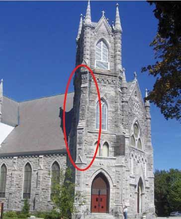
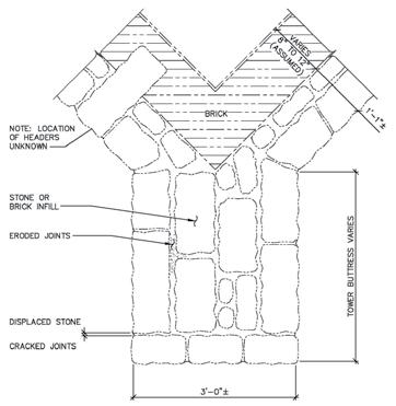
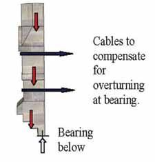


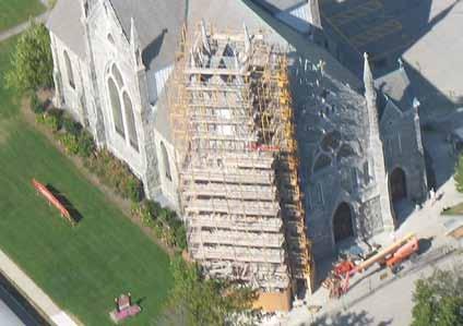
Figure 4: Tower with proposed cable locations. Figure 4: Tower with proposed cable locations.

Figure 3: Tower with personnel-access sca olding. Courtesy of Micahel Gnazzo.
and freeze-thaw had deteriorated the binding mortar inside the buttresses. Voids had developed due to the erosion of the interior mortar in both the buttresses and random areas of the walls of the tower. e walls were approximately 22 inches thick; the buttresses were approximately 3 feet thick. Figure 2 shows the section through one of the buttresses.
Restoration Repair
e intervention selected for the buttresses was to remove and rebuild them in the damaged areas, inject the voids in the adjacent walls and other buttresses, and pin the face stones of the walls at the injected areas. e buttress reconstruction included stainless steel anchors to bond the stones with the rebuilt masonry core. e reconstruction reused the existing stones. Proportionate to the wall thickness of the tower, the buttresses occupy the majority of the wall corner. If the buttresses were all to be removed simultaneously, the reduced section area of the masonry would cause the stresses in the remaining stones to be excessive. In addition, the tower would be become unbalanced because the buttresses against the building would not be removed to the same degree as the outer buttresses. Since a stability analysis indicated that removing and rebuilding all four corners simultaneously would be detrimental, the work was sequenced to avoid excessive stresses and to maintain stability of the tower. One option was to build a massive sca olding structure to shore and underpin the removal area. e cost was deemed excessive and alternate methods were considered. After several analyses, the work was planned so that it could be performed on two buttresses at a time by removing opposing corners to balance the load on the tower. e sca olding that was used was only needed for personnel access and to stage materials. It was not used for tower support (Figure 3).
e tower stabilization scheme was subdivided into both global and local actions. e global action was to wrap the upper portion of the tower with cables to resist overturning of the corners. In addition, the buttresses were removed two at a time, leaving the opposing corners intact. e local stabilization required that the stones immediately above the removal area be held in place to prevent movement.
Global Tower Stabilization
e goal of the stabilization procedure was to hold the top of the tower in place so that the buttress removal and reconstruction could occur without heavy shoring. e scheme utilized steel cables wrapped around the top of the tower. Figure 4 shows the tower before reconstruction, with the proposed cables located. e buttresses below the lower cable were to be removed and reconstructed down to above the main door entrance. Figure 5 shows a graphic with the buttress removed below leaving the upper portion overhanging. Figure 6 shows that the removals below would produce an eccentric load on the remaining
Figure 5: Overhang created by removals.
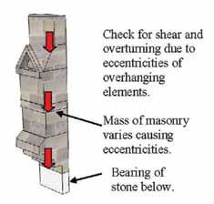
Figure 6: Upper stones produce eccentricity at overhang.
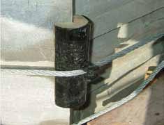
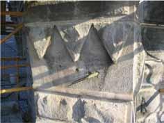
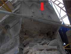
Figure 8: Corner protection for cable on stone. Figure 9a: Pinning upper stones before lower buttress removal. Figure 9b: Partial buttress removal below the the pinned stones in Figure 9a.
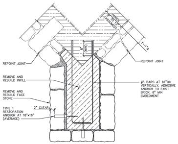
Figure 10: Detail of buttress reconstruction.
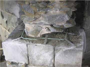
Figure 11: Stainless steel anchors to bond face stones.
masonry. Figure 7 (page 31) shows that, with very little bearing area remaining below the corners due to the removals, cables were needed to overcome overturning and provide a clamping force that would increase the shear capacity of the upper masonry at the corners. The two cables in Figure 7 were wrapped around the tower and tightened. The corner stones that were clamped by the cables were protected from damage by crush plates made up of a piece of steel pipe with a wooden filler that is formed to the edge of the stones (Figure 8). Alignment tabs were welded to the pipe for the cables. The extra cable shown in the lower portion of the photograph is not stressed.
Local Stone Stabilization
Prior to actual buttress removal, the stone just above the area was reanchored using drilled-in pin anchors to provide localized support and stability. Figure 9a shows the stainless steel pins being installed. These 1-inch-diameter steel pins were drilled and adhesive anchored into the backing material. After the restoration was completed, the pins were subsequently cut below the face stone and a patching material was used to cover the hole. Figure 9b shows the area below Figue 9a after the stones of the buttress below were removed. The pins from Figure 9a are shown by the arrow.
Buttress Reconstruction
Figure 10 shows graphically the reconstruction of the buttress. The core of the buttress was reconstructed and anchored to the brick backing wall using #3 reinforcing bars drilled and adhesive grouted 8 inches into the brick. The reinforcement was installed at 16 inches on center over the height of the buttress. Stainless steel ties were used to provide additional bonding of the face stones to the core of the buttresses by attaching them to the #3 bars (Figure 11).
Conclusion
Restoration interventions take many forms. However, the contractor must implement the intervention while maintaining the structure in a stable condition. This article provides some problems observed and methods used to stabilize a church tower during the construction phase. The methods were developed in cooperation with the masonry contractor.▪
David T. Biggs, P.E, S.E, DistM.ASCE, Hon.TMS (biggsconsulting@att.net), is a Principal at Biggs Consulting Engineering in Troy, New York.
Acknowledgment
This project was developed while the author was with Ryan-Biggs Associates, P.C. Matt Yerkey, P.E. is recognized for his significant efforts on the restoration project. Credit also goes to the Gnazzo Company of Connecticut that was the masonry restoration contractor.


