42 minute read
Structural Design


design issues for structural engineers
This is a story about designing brick masonry curtainwalls. It is a story because the events did not all occur on the same project. They all happened, just on different projects. For context and introduction, the author’s education is in solid mechanics followed by an early career in aerospace designing airplanes. Leaving the aerospace industry to design buildings wasn’t easy. Knowledge about the design of aluminum structures provided no respect from fellow building design engineers. When a small research project involving brick masonry came into the office, everyone else was suddenly too busy. The job turned out to be a blessing. It was easy to become an expert in masonry; there was no competition. There were also projects to design aluminum curtainwalls that no one wanted. Thus, by chance, the author evolved into a perceived expert in brick masonry curtainwalls. Moving forward 10 years, an email arrived from one of our project managers. “Are you availBrick Curtainwall for Essential Buildings able for a meeting with the Contractor, Owner, and Design Team to talk about the brick exterior wall this afternoon?” “Sure, where?” The answer back is, “Don’t know By John G. Tawresey S.E., F.TMS, yet – will let you know”. Two o’clock rolls around F. SEI and we were off to the meeting. The project is a large hospital, with over 500,000 square feet, in a seismically-active area that includes critical care, patient rooms, operating rooms and office space. The building is six stories with some five- and four-story sections and many corners. Our structural engineering firm had been working on the design with a noted architect for over six months. The gravity structural system John G. Tawresey S.E., F.TMS, is steel and the lateral system is concrete shear F. SEI, is the retired CFO of KPFF walls. The hospital is in a moderate-sized city that Consulting Engineers in Seattle, will service a large geographical area. The general WA. He received The Masonry contractor was on board, a large nationally known Society’s 2012 Paul Haller construction company, and the maximum project Structural Design Award, serves budget had been set. The architectural program on TMS 402/602 and ASCE 7 was complete. A lot of effort had been expended main committees, as well as on on the design of the patient rooms. They were the ASCE/SEI National Technical optimized for layout, including considerations Program Committee, and of available cabinetry and other equipment, and chairs the Professional Practices were approved by the hospital management and Committee of SEAW. John can be staff. The dimensions were set and the owner had reached at JohnTaw@aol.com. chosen a brick facade. Twelve or more people were at the meeting, plus a video conferencing set-up to connect with the design architect in another city. A quick look at the drawings revealed the wall was a 4-inch brick veneer, with a 2½-inch insulated cavity, ½-inch exterior board and a 4-inch metal stud. Total thickness was 11 inches plus ½-inch interior wallboard for a total of 11½ inches. The brick dimension was 4-inch nominal, which meant the specified dimension is 4 inches minus the thickness of the mortar joint used to lay the brick, or 35/8 inches. The specified thickness of the wall was actually 113/8-inch. The floor-tofloor height varied between 13 feet 43/8 inches and 17 feet 43/8 inches, or 60 courses and 78 courses with an extra 3/8-inch for differential vertical movement between the floors. The architect obviously did this before [standard modular coursing, 3 courses per 8 inches]. A quick calculation using 20 psf [85+ miles per hour stagnation pressure] and 400S162-54 studs at 16 inches on center resulted in a deflection of 0.6 inches for the 13½ -foot story height and 1.7 inches for the 17½-foot story height. This is a deflection of approximately L/270 and L/120 respectively. The contractor and architects seemed somewhat disconnected from the meeting. Only later did we learn the reason; this was the same wall system used on the previous job. One problem with being knowledgeable about masonry, you often are required to deliver bad news and often get shot as the messenger. Everyone was looking at the expert when I declared: “The 4-inch stud thickness is not adequate to support the veneer. And, a brick veneer on steel studs cannot meet the seismic drift requirements at the corners for an essential building.” The TV blinked and then went blank [it really did happen]. The lesson learned is to be less disruptive. It would have been much better to compliment the designers on their attention to modulation, ask what kind of brick [color] they intended to use and offer to look into the design. The bad news could then be delivered with a solution, and possible extra service fee at a later meeting. Instead, the contractor took control with one of those harsh and elevated voices. “The dimensions of the wall will not change.” The meeting ended with our project manager promising to look into it. There are standard criteria for the deflection of the veneer-backing wall. Unfortunately, the criterion don’t agree with one another. Numbers can vary between L/2000 to L/175. The International Building Code (IBC) does not provide a number. The L/2000 number will prevent any cracking of the brick veneer and the L/175 value is typical for the glass aluminum curtainwall industry. The Western States Clay Products Association recommends a value of L/360. The Brick Institute of America recommends a value of L/600. Service wind loading was used for calculating the deflection limit. There is some room for interpretation of the service wind load definition. Most will use unfactored wind loading from ASCE 7 (Components and Cladding). But, the 85+ miles per hour wind has a return period of 50 years. Could a lower value be used?
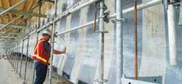
Figure 1. Girt system. changing to another curtainwall material. But, the owner was set on brick. Could we use thin brick set in 7½-inch precast panels and forget about the cavity? This was rejected because of the weight impact on the seismic design and the appearance, which usually does not look natural, not to mention the loss of the 2 inches of insulation. We could also add a horizontal girt system below the floor at the ceiling level to reduce the span. This last option, while adding significant cost, was the selected solution and solves the deflection issue (Figure 1).
Even at 50 miles per hour [stagnation pressure of 6.4 psf], the analysis predicts the brick veneer will crack [typically at the mortar joint]. But after cracking, the span is divided in half, which reduces the stress by a factor of 4. The consequence of a larger deflection is a larger crack opening [0.04-inch at L/360] and possibly more water infiltration as a result. The brick would remain attached to the backing studs because of the ties. But the wall will leak more. With a high quality air and water barrier behind the brick veneer [the project was to have one], the criteria of L/270 and ASCE 7 unfactored loads worked for the 13½-foot story heights. This could be the solution. The principal-in-charge jumped in. To stay within the standard of care usually exercised by structural engineers in the area at the time, the L/360 limit and ASCE 7 unfactored wind loading is common practice. Attorneys assessing the structural engineer’s performance relative to the standard of care often correlate more water to more deflection and if there is a water problem, then there is a structural problem and we would be sunk. What were we going to do? The meeting was scheduled in two days and everyone was extremely unhappy with us for creating this problem. Not our fault, but perceptions are reality. Internal meetings considered many suggestions, including But what about the performance of the brick veneer at the building corners? For the walls that are linear, the horizontal joint between floors, filled with caulk, could accommodate the seismic movement. But the joint doesn’t work at a corner and there were a lot of corners. The IBC “accommodation” of the seismic displacement Dp of 1.5 inches. What does accommodation mean for a brick veneer? Other sections of the IBC imply that the performance for a glass curtainwall is that the glass does not fall out of the frame. Could we imply from this that
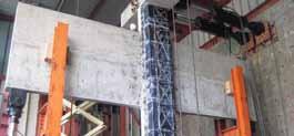
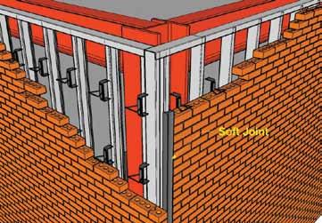
Figure 2. Soft joint corner. Figure 3. Isolated veneer backing.
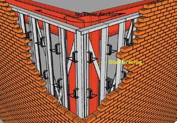
the criterion for a brick veneer is that no brick falls out of the wall and cracking will be OK? All agreed that this criterion would be acceptable, including the principal-incharge who then left the room. How to meet the criteria was the hard question! With the 1.5-inch displacement and ties close to the corner, all agreed that the ties would pull out of the masonry or disengage from the stud by stripping the screw or by a tension failure. Sections of the wall would likely disengage from the backing. Was the requirement for #9 wire joint reinforcement to engage the veneer tie a solution? No! Recent research demonstrated that adding the #9 wire joint reinforcement in the veneer to engage the tie did not help, and may reduce the capacity of the tie. (The requirement is no longer in the 2013 edition of the IBC.) It was clear that the conventional detailing of brick veneer at the corner does not satisfy the criteria. A suggestion was made to provide a control joint at the corner. This is a common solution. Architects hate the wide joints required, but sometimes accept them. The width of the joint would need to be 1½ inches or wider to allow for construction tolerances. Additionally, the joint would need to be close to the corner to minimize the stiffness of the return brick. The “eliminate the corner” option worked and sketches were prepared (Figure 2). Another engineer suggested isolating the backup stud wall system. This would require a detailed design of the stud wall. Bracing would be required and the stud-head-track would be designed not to attach to the floor above at the corner. This would also reduce damages to the interior finishes and the brick could be detailed as the conventional veneer (Figure 3). The project manager piped in: “There is no fee for this in our scope of work.” A fee proposal would be required with this option, or it could be a bidder-designed item and we could let the architect put it into the specifications. Oops, the principal-in-charge returned. “The bidder-designed option is not an option. I have been there before. The metal stud low bid sub-contractor will miss the requirement and have no money to do it right. This is the stuff claims are made of.” The author suggested reinforcing the veneer as a possible solution. This concept would replace the ties with floor and girt connectors. The reinforced structural masonry would span to the connectors. Connectors could be placed a distance from the corners, allowing the deflection to occur by warping of the wall [like a curtainwall]. The savings from the elimination of the ties [stainless steel was contemplated] equaled or exceeded the added cost of grout and reinforcement. But, past experience with owners, contractors and architects was mixed. The concept of warping brick corners was difficult to explain. Moreover, some of our own SE’s doubted it would work. Brick is a brittle material. “Is reinforced concrete a brittle material? Reinforced brick appears to demonstrate more flexibility in the curtainwall test conducted under AAMA 501.4 than reinforced concrete.” Who would do the design? It was not in our scope. Despite the doubt, a reinforced veneer is added as a solution along with a fee proposal (Figure 4). Sketches and presentation materials were prepared in a flat-out effort. With three proposals in hand, “elimination of the corner”, “isolated stud wall corner”, and “reinforced veneer”, we headed for the meeting, now at the owner’s headquarters.
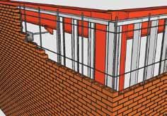
Figure 4. Reinforced veneer.
The air was thick. The perception was that this entire mess belonged to us. The General Contractor invited the CEO for the owner, and the design architect flew in from the faraway city. A mason contractor was invited to participate. The meeting began ……. The story doesn’t end here, just this article. Structural engineering is a great profession. Each situation is different and we get to solve many problems, most of them created by our clients. But, each day is different and in the end we get to participate in the creation of great projects.▪ Post Script: Don’t put a deflection limit in the IBC. One criterion does not work for all projects and clients. Moreover, adding a prescription to the code eliminates the opportunity to be creative. I prefer to be a consultant that uses judgment and experience to customize designs and recommendations for my clients. And, it offers the opportunity for a design fee that adds value to the project.
For more information on Reinforced Brick Veneer, see the Design Guide for Structural Brick Veneer from Western States Clay products Association at www.brickwscpa.org/publications.php.
The Sky is Falling!
No, It’s Marble!
Stone Repair at the Fairmount Cemetery Mausoleum
By Stephen H. Getz, BSCE
Failing anchors in marble ceiling panels limit access for ceremonies and visiting patrons for interred loved ones in the mausoleum (Figure 1). Constructed in the 1920s, the Fairmont Memorial Mausoleum is located on the 150 acre grounds of the Fairmount Cemetery in Newark, New Jersey. The 250 foot long by 92 foot wide “H” configured building has an exterior built of granite upon a cast-in-place concrete frame and concrete floor infrastructure. There are four functional levels to the building, including the basement. The interior walls and ceiling are veneered with 1- and 2-inch thick marble stone panels. The interior mausoleum environment was not conditioned for climate, and over nine decades of changing weather has challenged both the stone durability and anchorage connections.
Interior Stone Veneer Construction
The stone ceiling panels (Figure 2) are configured such that four (4) panels are butted to form a square. Each of the four panels has two edges common to another panel. They are suspended near center by copper wire ties attached to the stone edges by field-bending the wire to achieve about a 1-inch deep embedment in the stone. The wire’s opposing end is tied to the reinforcement bar of the floor above within a pocket created by chiseling the concrete cover to expose the ceiling rebar. The integrity and effectiveness of the existing ties are questionable, although such a system was not unusual at the time (Figure 3). Figure 4 illustrates the typical anchorage of the 8-gauge copper wire ties on a removed panel segment. Typically, the ties occurred at 12 to 16 inches from the unsupported free end, or mid-hallway location, of the panel. The outer perimeter of the 250 – 300 pound stone panels is supported by the vertical wall panels lining the hallway. The chase between ceiling panels and concrete differed by floor and the distance between the stone panel and concrete varied from 14 to 41 inches. The hallways throughout the building have marble encased concrete beams (Figure 4) occurring at approximately 8- to 10-foot intervals. Where concrete beams did not exist, a faux marble beam was provided for aesthetic continuity. The beams are covered on three sides with
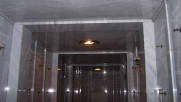
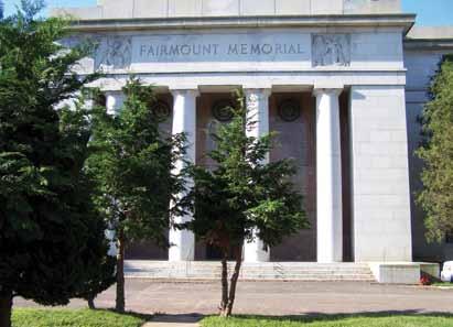
Figure 1. Exterior of the Fairmount Mausoleum.
one inch thick marble. The marble pieces span the hallway and are simply supported at the end. A center wire tie was observed in an inspection of an exposed beam. The length of the beams varies from 7 feet to approximately 10 feet in some areas. At most locations, the marble box is a nominal 18 inches wide by 18 inches deep.
Ceiling Panel Re-Anchoring
The untimely collapse of a ceiling panel alerted the owners to the potential dangers of future collapse, and that repair was essential and urgent. The task to remove and reset the hundreds of heavy ceiling panels and three piece marble clad beams was not financially feasible. The marble veneer providing a wall covering was intact and functionally sound. Accordingly, the project team investigated a cost effective supplemental anchoring solution. The challenges in developing the anchoring repair included: • Developing a post-installation anchor to bridge chase distances of 14½ to 43 inches; • The anchor must be capable of supporting a working load of 350 pounds tension and not induce tension loads on the existing marble panels; • The anchor assembly must interact with the stone panels so that a face mount anchor will support the stone panel without stone fracture; • Providing anchorage spacing and location dimensions that optimize anchor performance and does not over-stress marble;
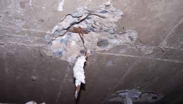
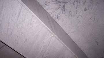
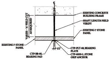
Figure 4. Typical 18- x 18-inch concrete beam enclosure in hallway. Figure 5. Details for ceiling anchors.
• Developing an anchoring scenario for stairwell ceiling panels installed at an angle to match the pitch created by the stairs; • Anchor finish must be aesthetically matched to the existing wall artifacts, sconces, gates and miscellaneous metal hardware; • Developing a beam enclosure anchorage system to capture and support the marble box beam enclosures; • Providing necessary installation means and methods criterion to assure marble and anchor combination effectively perform efficiently.
Anchors Developed
Marble Ceiling Panels For the basic ceiling panel anchor, CTP developed a ½-inch diameter brass expander element, torque activated for the concrete connection. Torque provides an important means of inspection and performance assurance. The anchor’s embedment depth in the concrete was tested at a minimum of 1½ inches that averaged over 1200 pounds capacity and induced a preload of 1060 pounds. These results provided safety factors greater than the industry standard of 4:1. The 4-inch floor in which the anchor would be fastened allowed the air space to vary 2 inches shorter, providing a standard shaft length for the variable condition. The head of the anchor is a 1½-inch diameter stainless steel round bearing plate capable of supporting the stone. The two elements are connected by a suitably long stainless steel shaft assembly (Figure 5). The marble ceiling panels were installed with corners butted at the center of the hallway. The 1½-inch diameter panel head would challenge the installation at this location due to the improbable ability to support each panel equivalently. As a result, a larger support area was required and a bearing plate was incorporated to support the panels in concert with the 1½-inch round panel head (Figure 6, page 24). Each bearing plate is manufactured of Type 304 stainless steel with
ADVERTISEMENT–For Advertiser Information, visit www.STRUCTUREmag.org
CTP Stitch-Tie
Helical Wall Tie System for Stabilizing Veneers and Crack Repair
Restoration Team Experience Since 1978 Masonry Façade Re-Anchoring Solutions SAVE THE WALL!
Don’ tTear itDown or Cover itwithInsulation andStucco
Strengthen and stabilize masonry façades while adding veneer stiffness for added decades of protection and comfort. CTP has engineered anchor performance solutions for claddings of brick and stone. A selection of corrosion resistant products are available to re-anchor brick to wood, concrete, steel, block, brick, metal stud, or tile back-ups.
CTP Stone-Grip
Mechanical Anchors for Stabilizing Stone Panel Veneers
ANOTHER O CTP RIGINAL!
NEW!
CTP GRIP-MAX *
* Patent Pending
CTP Grip-Tie
Mechanical Repair Anchors for Stabilizing Veneers CTP CT-16
For Brick Additions or Replacement; and for Brick Veneer Stud Cavity Wall Construction. Veneer Anchoring System That Keeps the Air Barrier Intact and the Veneer in Place.
Shown Here With: CTP Wall Tie
a Multifunctional Triangle Wall Tie That Can be Used in Standard or Seismic Veneer Anchoring Applications
Contact our Technical Services Team with your repair application needs for a cost effective and performance targeted veneer stabilizing solution.
Construction Tie Products, Inc. is committed to supplying the highest quality masonry tie and construction systems in North America and satisfying all stringent national codes and standards for today's building structures. CTP, Inc. promises to be a reliable product source along with on-time business integrity for all demanding builders.
7974 W. Orchard Drive Michigan City, Indiana 46360-9390 • USA Phone: (219) 878-1427 Contact: Steve Getz, BSCE www.ctpanchors.com
Figure 6. Typical ceiling support assembly. Figure 7. Beam enclosure anchor. Figure 8. Box beam enclosure assembly for an 18- x 18-inch beam.
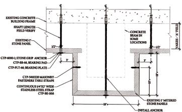
a brushed finish. The bearing plate design was predicated upon the panels being supported at the outboard edge. As a result of this support configuration, the bearing plate will carry one half the weight of the panel. The ceiling panels are installed as pairs, meeting at center line of the aisle way ceiling. The bearing pad used was to cushion the contact area of the steel member against the stone. Anchor assemblage components are manufactured of corrosion resistant materials. This style of anchorage was used throughout the project. The length of the anchors varied according to the cavity between the stone and the concrete slab, by floor. Three different anchor lengths were finalized after a field survey. Except for an extended drilling depth, all the assemblies followed the same installation instructions. This was an important feature in order to avoid customizing individual anchoring assemblies. Stairwell Marble Ceiling Anchors The assembly used in the stairwells for supporting the ceiling panels incorporates the same hardware as the ceiling panel support anchors. The panels in this area were installed to complement the stair rise and run angle. The panels are confined, and thrust loads due to the angularity were not an issue because of the panel confinement. A ceiling shim, manufactured of Type 303 stainless steel, was used to “normalize” the loading application from the plate to the Stone-Grip head. Beam Enclosure Support Assembly The beam enclosure support assembly incorporated the same style of anchorage to concrete used for other conditions. There are three (3) anchors per enclosure assembly and two encasements per beam (Figure 7). The anchor lengths vary with the depth of the beam. The box-style beams’ varying height and width required an adjustable support hardware configuration. Basically, in order to transfer gravity loads, intimate contact with the marble is essential for the support characteristics of the load carrying system to be effective. Each box beam assembly consists of two upper-side mounted brackets. They carry the weight of the box beam and can be adjusted both horizontally and vertically. Additionally, they provide support to the ceiling panel adjacent to the beam. Each bracket can carry 240 pounds. The top-side brackets are connected to a left- and right-side bearing bracket. This strap system envelops the beam and overlaps at the center of the beam bottom. Here too, the strap is capable of both vertical and horizontal adjustment to assure stone contact is made. Once the side brackets are positioned, they are bolted to the top-side brackets via a 3/8-inch stainless steel stud, nut and washer. The stud is factory welded to the side strap bracket. The intent is to support the beam in the event of a primary failure of the original tie/support system. Similar to the bearing plate detail, a “bearing pad” is used in the gravity bearing support areas. The top-side brackets and the left and right bearing brackets require bearing pads to insulate the stone from contact unit stresses. To prevent the box beam side-wall stone panels from collapsing inward, they are anchored to the left and right strap assemblies as a final connection of the hardware to the stone. A masonry fastener incorporating Type 360 brass expander elements with 18-8 stainless steel hardware was applied. These fasteners are torque activated to maintain intimate contact of the marble side wall panels with the support hardware. The anchor length allows a portion of the expander to project from the rear side of the marble. As the anchor is torque activated, it creates a “rivet” connection effect between the stone and steel strap. The bracket assemblies are manufactured of Type 304 stainless steel.
Summary
The finalized ceiling support assembly was used at 1,050 locations throughout the building for 1- and 2-inch thick marble. The marble beam enclosure and support assemblies were used at 370 locations throughout the building. The entrance level (first floor) and second floor required the center anchor to span a maximum of 31½ inches, and the two top supports 14 inches; the third level was 43½ inches at the center support and 25 inches at the top side supports. A critical element to the anchor installation was the method used to drill through the stone. Dry-drill carbide tip non-impact stone drilling bits were used for the task, as well as concrete drill bits 52 inches long having SDS drives to install the concrete anchors. The quality and resourcefulness of the project team contributed to a successful execution of the restoration project, and provided a result that fulfilled functional and aesthetic concerns while completing the project weeks ahead of schedule.▪
Stephen H. Getz, BSCE, is the owner and President of Construction Tie Products (CTP) in Michigan City, Indiana. CTP specializes in the development of masonry and stone cladding restoration systems. Steven continues participation in various trade related organizations that strive to develop relevant Standards and Codes aimed at the construction and preservation of quality masonry structures. He can be contacted at steve@ctpanchors.com.
A similar article was previously published in the The Applicator, 1st Qtr, 2014, produced by the Sealant, Waterproofing & Restoration Institute. Content reprinted with permission.
Guastavino Masonry shells
By John Ochsendorf, Ph.D.
In the late 19th and early 20th centuries, the Guastavino Company designed and built some of the most exceptional masonry structures in history. By adapting a traditional Mediterranean vaulting method to the demands of American construction, Rafael Guastavino Sr. (1842-1908) and Jr. (1872-1950) had a major impact across the United States. Between 1889 and 1962, the firm installed structural masonry vaults in more than 1,000 major buildings across the country, including long-span domes for numerous government facilities, museums, and religious buildings. By 1910, they were able to construct vaulting on an industrial scale, with more than 100 projects under construction simultaneously. A company advertisement from 1915 illustrates some of these domes (Figure 1). This article provides an overview of Guastavino vaulting and identifies noteworthy structural achievements by Rafael Guastavino, Jr. as well as calculation approaches for masonry vaults. Finally, the article describes the potential for Guastavino-style vaults to be built in the future.
History and Construction
The Guastavino method of masonry construction uses thin ceramic tiles, roughly 6 x 12 x 1 inches, which are laid flat in multiple layers. This method was considered to be revolutionary in the 14th century, when it was first described as being a lightweight and inexpensive method of construction compared to traditional stone vaulting (Figure 2). The tile vault appears to have been developed by Moorish builders near Valencia, Spain, though it quickly spread to become common throughout the Mediterranean region. The method is known as the bóveda tabicada in Spanish and is sometimes called the timbrel vault (so-named by Guastavino Sr.) or the Catalan vault (so-named by 20th century Catalan architects). When compared to traditional stone vaulting, tile vaulting uses much less material and can be built much more quickly. Because the thin bricks are laid flat, with their narrow edges in contact, the total thickness of the vault is less than conventional masonry, and therefore the self-weight and corresponding horizontal thrust values are reduced. In the traditional tile vault, the tiles are joined with plaster
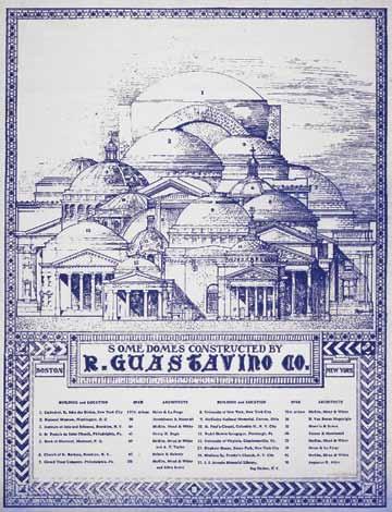
Figure 1. Advertisement for the R. Guastavino Company (ca. 1915) (Source: Avery Library, Columbia University).
of Paris, which sets quickly enough that the interior of the vault does not require any support from below during construction. By contrast, a traditional stone arch must be supported on wooden centering, or formwork, and will only support its own weight once the keystone is in place. By building out from a wall in successive arcs, tile vaulting can be constructed with minimal to no formwork. In addition, the inherent fire resistance of the tile vault was a major selling point for the Guastavino Company in the late 19th century. Though other builders had brought the tile vaulting method from Spain to the Americas as early as the 16th Century, Rafael Guastavino
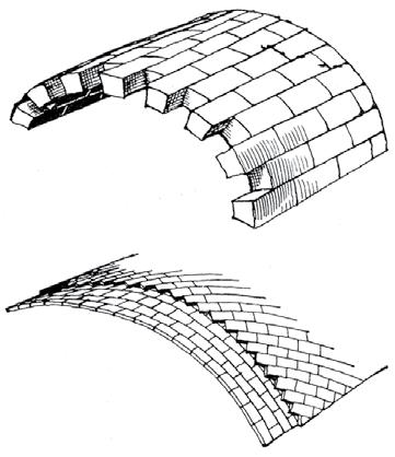
Figure 2. Comparison of the traditional stone vault (a) and the Guastavino tile vault (b) (Source: Moya, 1947).
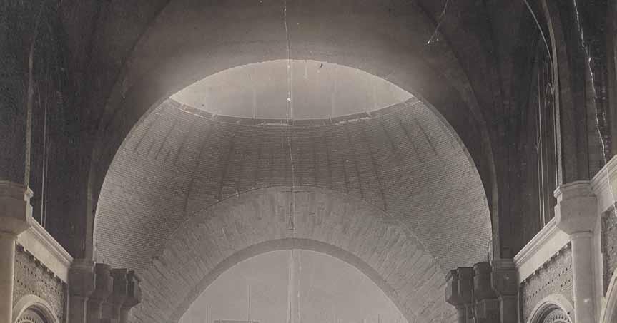
Figure 3. Grace Universalist Church by Rafael Guastavino Jr., Lowell, Massachusetts, 1895 (Source: Avery Library). Figure 4. Crossing dome of the Cathedral of St. John the Divine by Rafael Guastavino, Jr., New York City, 1909 (Source: Avery Library).
Sr. and Jr. introduced numerous innovations to the traditional tile vault, which allowed them to secure dozens of U.S. patents to protect their product. Guastavino Sr. was educated as both an architect and an engineer at the school of “masters of works” in Barcelona in the 1860s, by the same professors who would later teach the Catalan master Antoni Gaudi (1852-1926). In Barcelona, Guastavino Sr. constructed a series of major industrial factories as well as numerous houses, all using the traditional tile vault as the load-bearing structure for floors and staircases. His last major work before immigrating to the United States in 1881 was the La Massa Theater in Vilassar de Dalt, with a 56-foot span built of unreinforced masonry only 4 inches thick. This astonishing thinness is possible because of the double-curvature of the masonry shell, which allows for compressive load paths to be transferred to the supports in multiple directions. With minimal English and few professional contacts in the United States, Guastavino Sr. initially struggled to earn a living as a newlyarrived immigrant. Eventually he got his break when he was contracted by the leading firm of McKim Mead and White to build structural tile vaulting throughout the Boston Public Library in 1889. This launched his American career and led to dozens of other contracts for structural tile installations in the 1890s. His son, Rafael Jr., had no formal education in architecture or engineering, but after apprenticing under his father, went on to build some of the most daring masonry structures in history.
Structural Achievements by Rafael Guastavino Jr.
Guastavino Jr. supervised the construction of an impressive church dome in 1895 when he was only 23 years old (Figure 3). The 70-foot span tapers in thickness from 6 inches at the support to only 4 inches at the crown of the dome, and the span-to-thickness ratio of roughly 200 is twice as thin as an eggshell by proportion. This dome was built in less than two months and was self-supporting throughout construction, with minimal formwork to guide the geometry. Because tensile hoop forces would appear in the lower region of the spherical shell – below about 52 degrees as predicted by membrane theory – Guastavino provided a tensile band of steel to resist the outward thrust at the intersection of the buttressing barrel vaults and the dome. As
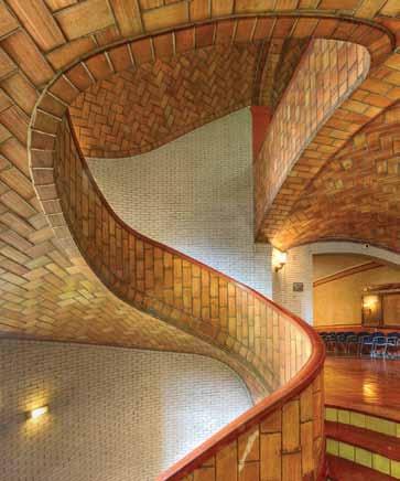
Figure 5. Tile vaulted staircase of Baker Hall, Carnegie Mellon University, Pittsburgh, 1914. Courtesy of Michael Freeman.
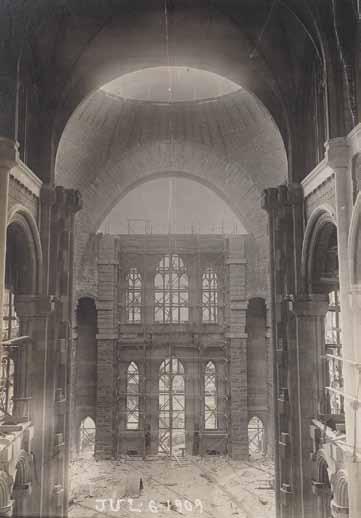
with his father’s dome at La Massa, structural shells of this scale and proportion would not be constructed in thin shell concrete until decades later. In some ways, the Guastavino shells are superior to the later reinforced concrete shells because of the absence of formwork as well as the minimal reinforcing steel. Hundreds of Guastavino domes have functioned as safe structures for more than a century, and none have ever failed in service. The largest dome ever built by the company is the 135-foot span for the Cathedral of St. John the Divine in New York City (Figure 4, page 27 ). Shortly after his father’s death, Guastavino Jr. proposed the dome as a temporary solution over the crossing of the cathedral. By following a spherical geometry, the dome could be built using only cables to guide the placement of tiles, while the masons were supported on the concentric rings of tile as the project cantilevered out into space. This great feat of construction was completed in only 15 weeks during the summer of 1909, and was heralded as an achievement to rival the great masonry domes of antiquity. As in other Guastavino domes, the total thickness at the crown is just over 4 inches, and steel tensile reinforcement at the base helps to restrain the outward thrust of the dome. More than a century old, the dome still stands today as a testament to Guastavino Jr’s skill in both structural design and construction. Though smaller in scale than the large domes, Guastavino spiral vaulted staircases represent an additional category of structural achievement. The main staircase of Baker Hall at Carnegie Mellon University is a masterpiece of Guastavino construction, with a 4-inch thick shell of masonry spiraling in three dimensions (Figure 5). The load-bearing masonry structure is made only of brittle ceramic tiles and does not contain reinforcing steel. The stair is constrained by a cylindrical brick structure, which resists the outward thrust of the vaulted staircase. Though calculating the ultimate load capacity of such a structure is extremely difficult even today, the Guastavino Company conducted many successful load tests, and the survival of the stair for the last century is proof of its adequate load capacity.
Mechanics of Masonry
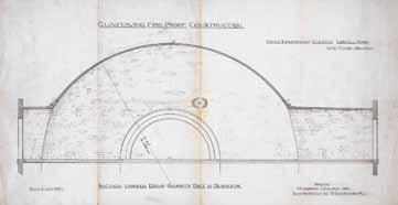
Rafael Guastavino Jr. calculated the forces in his vaulted structures using compressive equilibrium solutions defined by graphic statics, and he often shaped the structures to respond to the flow of forces, placing masonry where the resulting thrust lines acted (Figure 6 ). The goal of the calculation is to demonstrate safe equilibrium solutions under all possible load cases, and to ensure that the resulting thrust lines do not exit the masonry. This follows in the tradition of limit analysis of masonry as developed by Jacques Heyman since the 1960s. The stresses in traditional masonry structures are quite low, and the safety of such structures is typically governed by stability and not by strength. By contrast, it is very difficult to demonstrate the safety of thin masonry shells using finite element methods, which seek to minimize the strain energy by invoking assumptions about the material behavior. Such elastic solutions predict substantial tensile stresses in traditional masonry and are highly sensitive to small movements of the supports. The calculation methods used by the Guastavino Company are similar to those used by the leading concrete engineer Robert Maillart and the great shell builder Felix Candela: they are based primarily on static equilibrium and not on the vain search for exact stress distributions in a hyperstatic structure. While assessing the safety of Guastavino structures remains a challenge today, new methods of equilibrium calculations can help today’s engineers to discover load paths that these masonry shells have effortlessly found for more than a century. Several recent projects have demonstrated the potential for structural masonry shells to be built today. For the Pines Calyx project in England, two masonry domes span approximately 40 feet as the primary structural system (Figure 7). Similar to the unreinforced Guastavino masonry shells, the domes are constructed of three layers of thin tile, and the outward thrust is resisted by a tension tie at the
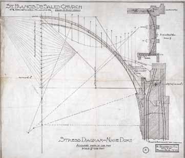
Figure 6. Graphic statics used by Guastavino Jr. to calculate the compressive forces in the dome of St. Francis de Sales Church in Philadelphia, 1909 (Source: Avery Library).
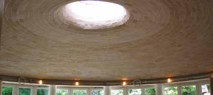
base. The domes were self-supporting during construction, and a central oculus admits natural light and ventilation. Equilibrium calculations based on the membrane theory and graphic statics were used to demonstrate the safety of the structure during construction and under asymmetrical live loading. Due to the use of local materials and the minimization of structural steel, the embodied energy in the structure is dramatically lower than conventional steel or reinforced concrete structures.
Conclusions
The thin structural shells of the Guastavino Company Figure 7. Structural tile dome, Pines Calyx, St. Margaret’s Bay, England (2005).TAY24253 BraceYrslfStrctrMag.qxd 9/3/09 10:09 AM Page 1 are some of the most impressive masonry structures in the world. In particular, the large domes and remarkable staircases by Rafael Guastavino Jr. are worthy of additional study by both engineers and historians. More than 600 existing projects in YOU BUILD IT. WE’LL PROTECT IT. more than 40 U.S. states contain examples of Guastavino masonry vaulting, though SEISMIC PROTECTION new projects are being rediscovered each year. The engineering calculation of thin FROM TAYLOR DEVICES masonry shells presents an open challenge, Stand firm. Don’t settle for less than the seismic protection and the engineer must find three-dimen- of Taylor Fluid Viscous Dampers. As a world leader in sional compressive solutions that lie within the science of shock isolation, we are the team you the thickness of the masonry. Attempts to want between your structureand the undeniable forces prove the safety of existing structures can ofnature. Others agree. Taylor Fluid Viscous Dampers also lead to the discovery of new structural are currently providing earthquake, wind, and motion forms that have not yet been invented. The protection on more than 240 buildings and bridges. minimization of reinforcing steel and From the historic Los Angeles City Hall to Mexico’s the use of local materials can inspire engi- Torre Mayor and the new Shin-Yokohama High-speed neers to design and build new masonry Train Station in Japan, owners, architects, engineers, vaults in the future, with the and contractors trust the proven hope of matching the success technology of Taylor Devices’ and longevity of Guastavino Fluid Viscous Dampers. tile vaulting.▪
John Ochsendorf, Ph.D. (jao@mit.edu), is a structural engineer specializing in the mechanics and construction of historic masonry. He is the Class of 1942 Professor of Engineering and Architecture at the Massachusetts Institute of Technology and is author of the book, Guastavino Vaulting: The Art of Structural Tile.
For More Information
A public exhibition on Guastavino vaulting, including original design drawings and a full-scale replica vault, is on view at the Museum of the City of New York until September 7, 2014. For further reading on the subject, the online version contains an extensive list of suggested texts. Visit www.STRUCTUREmag.org. Taylor Devices’ Fluid Viscous Dampers give you the seismic protection you need and the architectural freedom you want.
www.taylordevices.com
North Tonawanda, NY 14120-0748 Phone: 716.694.0800 • Fax: 716.695.6015
Tensioning Masonry to New Heights
Armory Park Elderly Housing Project
By Kelly Robertson, P.E. and Paul Scott, P.E., S.E.
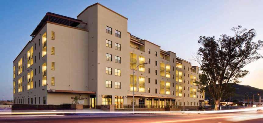
The tallest post-tensioned masonry building in the United States was completed in 2013 in Sentinel Plaza, an Independent Senior Housing Development, in Tucson, Arizona. The new building is six stories high with 139,000 square feet and 143 units (Figures 1 and 2). Within the Sentinel Plaza Development was an existing building called Armory Park. Armory Park, a HUD 202 building, had been determined to be outdated and needed to be replaced. SHG (Senior Housing Group), using Arizona Low Income Tax credits, took on the task of building the replacement building, which is also called the Armory Park building. The Sentinel Plaza Development requires sustainable architecture design for the buildings in the development. Armory Park was designed to meet LEED (Leadership in Energy and Environmental Design) Gold standards. Roof mounted solar modules offset 75% of the common area’s electrical loads. Landscaping uses drip irrigation, low water use native plants and passive water harvesting. High efficiency mechanical units, low water use plumbing features and high performance windows were used.
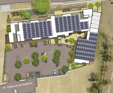
Figure 1. Elevation.
As a part of achieving the LEED Gold, the exterior walls were required to contribute to the energy savings by having an average R value of 16. Four exterior wall systems were evaluated/considered:
Masonry Walls Pros
• Masonry is a common exterior wall system in Tucson, AZ. • The exterior masonry walls can be the Post-Tensioned Masonry
Wall System and achieve an R = 19 for 8-inch thick CMU (concrete masonry unit) walls. • Grout and rebar can be used in masonry for detailing as required by structural calculations. • Masonry is a very durable exterior wall surface.
Cons
• Masonry is not viable as the exterior wall unless a significant R value can be achieved with the masonry wall or with furred out walls with insulation.
Concrete Walls Pros
• Concrete is a common exterior wall system in Tucson, AZ. • Concrete is a very durable exterior wall surface.
Cons
• Concrete walls cannot achieve an R of 19 unless the walls are sandwich panels with Styrofoam/ high density polystyrene in the middle of the concrete wall, or if walls are furred out and insulation is used in the furred out walls.
Steel Studs Pros
• Steel studs are a common method to build exterior walls in
Tucson, AZ. • Insulation can be placed between the steel studs to achieve the required wall R value.
Cons
• The steel studs allow for thermal transfer of heat/cold from the exterior to the interior through the steel webs of the steel studs. • The exterior material (stucco over gypsum board) on the steel stud walls is not as durable as masonry or concrete exterior walls.
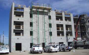
Figure 3.Under construction.
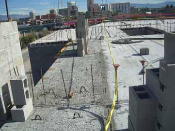
Figure 4. Plank floor with CMU bearing walls.

Figure 5. Building under construction.
Insulated Concrete Forms (ICF) Walls Pros
• ICF walls can provide the wall R value required.
Cons
• ICF walls are not as common as masonry, concrete, or steel stud exterior walls in Tucson, AZ. • The exterior material (stucco over the insulating foam form) is not as durable as masonry or concrete walls. The original LIHTC (Low Income Housing Tax Credit) application included ICF as the load bearing & insulated exterior wall system. The general contractor (W.E. O’Neil) suggested post-tensioned masonry as an alternate system for several reasons: durability, ease of construction, and similar insulating characteristics. Additionally, the CMU
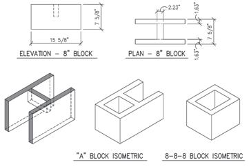
Figure 6. Detail of standard CMU units.
met LEED requirements for local sourcing. After an evaluation of the relative cost, schedule impacts, and LEED requirements, a posttensioned masonry wall system was chosen to be used as the exterior wall (Figures 3, 4 and 5). Superlite Block (an Oldcastle Division in Phoenix, AZ) developed the “Post-Tensioned Masonry Wall System” (Integra) in 1984. The post-tensioned system was developed in order to provide a structural masonry wall with significant R value. Superlite was issued an ICBO report in 1991, which is now ICC Legacy Report ER-4845. (This ICC approval preceded the development of the Prestressed Masonry chapter in the Building Code Requirements for Masonry Structures (ACI 530/TMS 402/ASCE5) and is still being used. The ACI 530 is available for prestressed masonry design and is used by most designers.) The post-tensioned system can be designed using either Allowable Stress Design (ASD) or Ultimate Strength Design (USD) as outlined in the ICC Legacy Report. ASD was chosen for this project, as ASD has been used in the majority of Integra projects done to date. The design procedure used follows the simple design principles: P/A and M/S. The allowable stresses in the Legacy Report are based on full scale load tests done in 1991 at the NCMA (National Concrete Masonry Association) Lab in Herndon, VA. The allowable stresses are as follows: Axial Compression – 360 psi Axial Tension – Not Allowed Bending Compression – 540 psi Bending Tension – 22 psiI Shear – 59 psi The system uses 7/16-inch diameter smooth steel rods as the posttensioned rods (PT rods) with Fy min = 60 ksi. The post-tensioned rods are tensioned to 7,400 pounds and the usable tension in each rod is 5,000 pounds taking into account the losses. See Figure 6 for the CMU units used. The post-tensioned system was designed initially to be used as an exterior residential wall. However, it has also been used in many commercial projects like the Armory Park project. The main differences, in residential versus commercial design, are the magnitude of the loads, the height of the walls and the size of wall openings. There have been some residential projects where all of the masonry walls have been post-tensioned, meaning no grouted cells were required. Those structures can use the total R = 19 for an 8-inch thick wall. Most residential and commercial post-tensioned projects require some locations in the wall with solid grouting or solid grouting with rebar, therefore an average R value can be computed. For example, wherever there is a need for a bolted connection of a ledger to a wall, the bolts are placed in a solid grouted bond beam with two
N
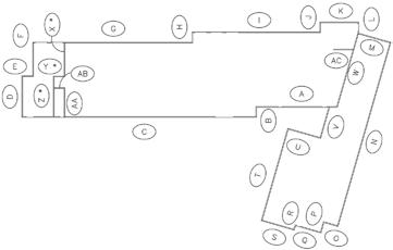
Figure 7. Key plan of wall elevations.
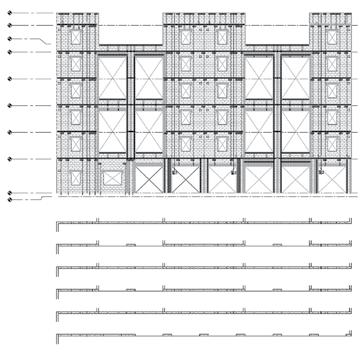
Figure 8. Partial north elevation “I”.
pieces of rebar. Wherever there is an opening large enough that the post-tensioned system won’t work, a reinforced solid grouted jamb is designed.
Structural Factors
• The seismic response modification coefficient R for ordinary reinforced masonry walls is 3.5 versus 1.5 for the R of ordinary prestressed masonry walls (Reference Table 12.2-1 ASCE 7-05).
Discussion – The seismic lateral loads were larger than the wind lateral loads, so using an R of 1.5 versus an R of 3.5 increased the lateral loads on the building. The increase in lateral loads turned out not to be a significant design concern because the amount of masonry walls available was adequate for the R = 1.5 and the interior party walls were reinforced masonry, not post-tensioned. • There were concerns that the masonry contractor would have difficulty determining where the post-tensioned CMU occurred versus the conventionally reinforced CMU.
Discussion – The post-tensioning structural engineer decided to provide elevations of all the exterior walls. The elevations showed
every concrete masonry unit and, through the use of different shading and hatching, the post-tensioned CMU could be distinguished from the conventionally reinforced CMU. Every post-tension rod was shown, every piece of re-bar was shown and grout locations were shown (Figures 7, 8 and 9). • Post-tensioning didn’t work at all of the exterior walls.
Discussion – The post-tensioning system was used for the entire six stories at the non-bearing walls. At the bearing walls, the compression due to the vertical loads and the post-tension rods compressing the walls was significant. Therefore, only the top two floors are post-tensioned at these locations. • Detail coordination between building engineer (SEOR) & the
Post-tensioning Designer.
Discussion – Because post-tensioning is often treated as a deferred submittal in the design process, the Structural
Engineer of Record has typically already completed the structural detailing prior to the post-tensioning being designed.
The structural details may show conventional masonry or they may dash in the post-tensioning masonry walls to be designed by others. In the case of Armory Park, the completed details by the SEOR showed the post-tensioning masonry dashed in, so the design team was able to base the connection details off of the structural details and include the information required for the post-tensioning construction. This coordination allowed the details to appear consistent between the structural drawings and post-tensioning drawings, and each consultant was able to review the details and verify acceptability prior to being finalized (Figures 10, 11, 12, and 13). Quest Energy Group provided the energy modeling services for the building. TestMarcx Commissioning Solutions provided commissioning for LEED for Homes Midrise credits EA Pre-requisite 1.2 (Energy & Atmosphere Optimize Energy Performance: Testing and Verification) and EQ 12.1 and 12.2 (Indoor Environmental Quality:
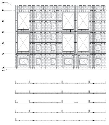
Figure 9. West elevation “T”.
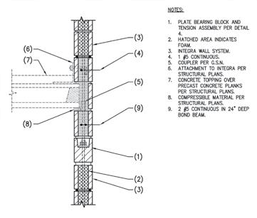
Figure 10. Detail of precast concrete at post-tensioned wall: bearing.
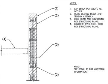
Figure 12. Detail of concrete over steel deck at post-tensioned wall.
Prerequisite And Enhanced Compartmentalization of Units). Pima County Development Services Green Building Program served as the LEED for Homes Provider and Green rater, and also provided Durability Management Verification (credit ID 2.3). The post-tensioned masonry system contributed to the following LEED midrise points: • ID 2.1, 2.2 and 2.3 (Quality Management for Durability) • ID 3.1 (Innovation and Design for exemplary performance in
SS 5 Pest Control) • SS 5 (Nontoxic Pest Control) • EA 1.1 and 1.3 (Minimum and Optimize Energy performance) • MR 2.2 (local production, exterior wall) Throughout construction, all lines of communication ran through the architect, so that all consultants would remain coordinated. Because of the thorough coordination effort during the design process, field coordination issues were kept to a minimum. With this practice in place, the award-winning Armory Park project was successfully completed ahead of schedule.▪
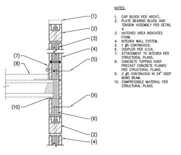
Figure 11. Detail of precast concrete at post-tensioned wall with parapet: bearing.
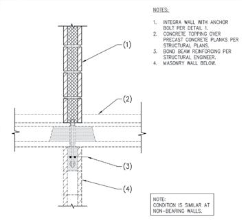
Figure 13. Detail of post-tensioned wall above conventional CMU wall.
Project Team
Owner: Senior Housing Group, Tucson, AZ Structural Engineer of Record: Schneider & Associates Architect: Lizard Rock Designs, Tucson, AZ General Contractor: W.E. O’Neil, Phoenix, AZ Masonry Contractor: Hobbs Masonry, Phoenix, AZ Masonry Supplier: Superlite Block , Phoenix, AZ Post-tensioning Design Structural Engineer: Caruso Turley
Scott Inc.
Kelly Robertson, P.E., is a structural engineer at Caruso Turley Scott, Inc. in Tempe, AZ. She can be reached at krobertson@ctsaz.com. Paul Scott, P.E., S.E., is a Partner at Caruso Turley Scott, Inc. He can be reached at pscott@ctsaz.com.


