22 minute read
InSights


By Duncan Paterson, P.E., Ph.D.
When we think of bridge health evaluation, the traditional means and methods have been inspection by engineers in the field and ratings based on loading assumptions. Bridge inspectors are the original non-destructive evaluators, using observation and diligent records to establish how a bridge is performing during its life cycle. The term NonDestructive Evaluation (NDE) has a greater implication, though; we are doing more than a visual evaluation. NDE is becoming the term to differentiate between what we think of as customary inspection techniques, and using advanced electronics and data evaluation. A subset of NDE is Structural Health monitoring (SHM), a term that indicates response monitoring, damage detection system(s), or other observation systems for structural response over time. SHM has steadily increased in the bridge community’s vernacular over the past few decades. Once, the thought of placing system response instruments on or near bridges was solely the domain of academia and research. SHM, however, has the capability to provide a direct link between loads and bridge behavior; it can surpass traditional assumptions for ratings and provide actual structural response to loads. SHM has been evolving since its inception as a means to establish the effects of load on bridges and structures. The main workhorses of SHM remain strain gages, tilt-meters, accelerometers, and displacement gages. For those not familiar with these devices: strain gages evaluate a nominal displacement of a surface over a known gage length; tilt-meters measure the change in rotation; accelerometers measure the rate of change in position; and displacement gages measure movement with respect to a fixed reference. Each of these instruments is limited to the specific location where it is placed. With these instruments, we are able to monitor how bridges strain and move under load in real time. Taking it one step further, engineers can do things such as evaluate local stresses at fatigue details, monitor earthquake accelerations, calibrate finite element models, or monitor real-time response as a super-load crosses a bridge. A realization arose in the bridge evaluation community that there is a great opportunity
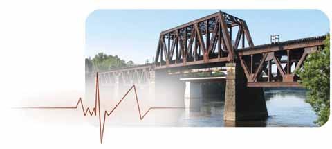
Structural monitoring can show real-time response to live loads.
to combine traditional inspection techniques and structural response monitoring to obtain a more complete picture of the health of a bridge. In one respect, inspection is still vital to grasp an overall evaluation of a bridge. A visual inspection by a trained engineer provides a wealth of information. However, a visual inspection can’t see the stress in a structural member under live load. It can’t see the out-of-plane transverse deflection. Moreover, an inspector can’t be on site for 24 hours a day, every day. On the other hand, SHM monitoring can indicate the stress in a member, and it can determine structural movement. But, as of today, it can’t provide an overall view of a bridge that a visual inspection can. So, in pairing the two, SHM becomes a rather powerful option for assessing the health of a bridge. It has become another tool in the engineer’s tool box. One of the best uses has been to verify structural live load response where the behavior is questionable or unknown (e.g. live load distribution). There are other advantages to SHM beyond evaluating an instantaneous response to load. Long term monitoring can aid in event response. For example, what happens to a structure at the precise moment it incurs an extreme load? Engineers and owners might also be interested in long term monitoring to capturing a maximum response over a period of time, or to monitor the effects of weighin-motion traffic, or to capture a complete load history for a fatigue evaluation. If we have instruments in place to monitor long term response, we have the ability to capture an abnormal event such as a vehicle strike or an extreme overload. In a practical real-world example, a simple accelerometer was placed on a bridge because the owner thought it was getting struck by trucks bi-monthly, or so. They set an alert to be triggered every time there was a horizontal acceleration that exceeded a certain threshold, and snapped a picture of the event. As it turns out, once the device was installed, the first e-mail alert went off the same night they activated the system. The alert message started firing once or twice a day, and provided evidence of each hit. Information like this can be vital in prioritizing decisions in a bridge management program. But SHM isn’t always that simple. For example, SHM has the ability to create massive volumes of data without the ability to process what is being recorded. With a new flood of data, one of the most important advances for SHM will be the development of data management systems. Other industries have adapted self-learning computer programs, and the same should be done for long term monitoring for SHM. The type and level of instrumentation continue to evolve as well. Fantastic techniques, like image correlation and adaptation of ground-penetrating radar, are opening up the possibilities of taking the aspects of a visual inspection and incorporating them digitally. There are also possibilities to integrate SHM into our daily management of bridges. According to Zee Duron, Engineering Department Chair of Harvey Mudd College “Engineers have got to get smarter about what the sensors are telling us, and we’ve got to get more politically astute in terms of how we take that information and turn that into economic and public policy that actually improves the infrastructure of the United States.” Conversely, John Fisher, Professor Emeritus at Lehigh University stresses instrumentation should be judiciously applied, “It has to be rationalized because, one, there’s a cost associated with it, and two, why make measurements if they’re not needed?”▪
Duncan Paterson, P.E., Ph.D., is a Professional Associate and Sr. Bridge Engineer with HDR Inc. in Cincinnati, OH.
As a life-long San Francisco Bay Area resident, I was motivated to write this letter when I read the two articles published in the February 2014 issue regarding the San FranciscoOakland Bay Bridge. I found the articles topical and provocative. However, if we are to improve rush hour traffic through the San Francisco-Oakland-Berkeley corridor by considering the addition of a second identically configured parallel bridge adjacent to the existing one, I would have liked to have seen some of the more obvious questions/issues addressed: 1) Can the existing freeways at either end of the proposed second and existing bridges handle the greater number of vehicles on the two bridges so that the overall traffic situation would be improved? 2) What would be the cost of the new surface roadways, connector ramps and access points, and perhaps new freeways required to join to the new bridge? Where would these roadways be located and what would be the environmental impact (traffic, business, noise, views, etc.) on the cities of San Francisco, Oakland and Berkeley? 3) Assuming that the original 1930s bridge design was ideal, what would be the engineering and cost rationale for building a new bridge with re-used, archaic 1930s members, rather than just using new materials with an improved double deck configuration? Is it necessary to replicate the clear span of the Eastern span cantilever section? 4) Would it be practical and cost-effective to dismantle the existing bridge in such a manner as not to damage the individual elements, so that they could be stored and reconstructed later?
THE SOCIET O Y F NAVAL ARCHITECTS & MAR I N E ENGINEERS •
PPORTUNITY collaborateexperience develop attend learnsharemeetjoin
We can help you get a head start, get ahead, get recognized, and give back. No matter what stage of your career, SNAME has opportunities for you.
5) Since the original Eastern span is widely considered unattractive and a long-standing insult to the residents of the East Bay, would it be possible to get public support for its reconstruction? I agree that the new Eastern span has not made the vehicular traffic situation any better; it actually seems worse now, if that is possible, and it is likely to get even worse in the future. But since the new Eastern span has just opened after 25 years of design and construction and at a huge cost to the taxpayers, not to mention the question of whether it was an appropriate or efficient engineering design, I must admit that adding another bridge in essentially the same place did not cross my mind. I have not really recovered from the last project. Besides, the concept of adding another cross-bay bridge south of San Francisco to the East Bay, also known as the “Southern Crossing,” has been studied in various alignments and locations since the 1940s, but consistently rejected. As an alternative to more bridges and roadways, increasing the capacity and service area of the BART rail system deserves serious consideration as a means of reducing the demand on the existing Bay Bridge. Maybe a Southern Crossing with shared vehicular and BART rail traffic could be part of a comprehensive traffic improvement plan. Some people like to ride ferries, but I think that the time for that technology, as a serious contributor to traffic capacity, is in the past, although it might play a small part in the future. Before we consider a second Bay Bridge, we really need an in-depth study to flush out the best alternatives and the true costs. John Dal Pino, S.E.
jdalpino@degenkolb.com
P.S. Saving the old Eastern span is really a moot point, since demolition is already underway.

Response to John Dal Pino’s “Letter to the Editor”
These are all good points. We share the concerns raised by Mr. Dal Pino, and assume that various transportation agencies share them, too. The combined factors of high costs and lengthy construction time devoted to replacing the east span have likely exhausted any public enthusiasm for an additional bridge. Even so, substantial increases in public transportation budgets will not provide adequate relief where it is most needed. A second underwater tube for BART, for instance, is unlikely to address the true nature of the congestion. The only viable solution is a second bridge. We believe the challenges associated with a second crossing can be surmounted. While space does not allow us to expand on our ideas for why a parallel bridge has practical and economic advantages, we also readily acknowledge the potential for other viable bridge options. Ultimately, we believe that a multi-stage design competition would get the best ideas on the table. Regardless of aesthetic preferences related to structural systems (steel truss vs. concrete viaduct), the fundamental question remains: “How long do we delay plans for an additional crossing, and at what ultimate cost?” We feel engineering professionals are better suited to tackling this question pro-actively, rather than waiting for it to make the agenda of elected officials. Ronald F. Middlebrook, S.E. and Roumen V. Mladjov, S.E.
John A. Mercer Jr. Retires from STRUCTURE ® Editorial Board
John A. Mercer Jr., P.E., is stepping down as a member of the STRUCTURE magazine Editorial Board. John joined the Editorial Board in December 2003 as a CASE representative. He is President of Mercer Engineering, PC, a structural engineering consulting firm located in Minot, North Dakota.
Jon Schmidt, P.E., SECB, Chair of the STRUCTURE magazine Editorial Board, had this to say on John’s departure: “John Mercer is one of the longest-serving members of the Editorial Board. It has been an honor and a pleasure to work with him throughout my time as chair, and we will all miss his valuable perspective. I wish him the best as he continues to serve the profession in other ways.”
Regarding his tenure on the Board, John commented: “Serving the structural engineering community by participating and representing the Council of American Structural Engineers (CASE) on the Editorial Board of STRUCTURE magazine has been one of the highlights of my career. I’ve been privileged to meet and work with some of the giants in our profession. People like Walter Hanson who authored one of my university texts on soils engineering is just one example. The team approach of CASE, NCSEA, and SEI in supporting STRUCTURE magazine undergirds my mantra, TEAMS WIN! individuals wither… I want to thank you the reader, the article authors, and all of the members of the Editorial Board that I have been blessed to have worked with in making STRUCTURE magazine the best and most exciting periodical for structural engineers on the planet!”
John A. Dal Pino, S.E., will replace Mr. Mercer as one of three CASE representatives to the Editorial Board. Mr. Dal Pino is a Senior Principal at Degenkolb Engineers in San Francisco, CA. He is a licensed Structural Engineer in California with over 30 years of experience. John’s broad range of project work includes the design of new buildings, structural evaluation and strengthening of existing buildings in areas of high seismic hazard, renovation of historic buildings, deep excavation bracing and other construction-related activities, John A. Mercer Jr., P.E. John A. Dal Pino, S.E.
structural plan review and seismic peer review. John is a San Francisco native and has lived in the Bay Area his entire life.
Jon Schmidt said this about Mr. Dal Pino’s appointment: “I am happy to welcome John Dal Pino as the newest CASE representative on the Editorial Board. He has already hit the ground running, by submitting a letter to the editor that appears in this issue.”
Please join the STRUCTURE magazine Editorial Board in welcoming John Dal Pino.
book reviews and news
Bookcase
Reinforced Masonry Engineering Handbook
Clay and Concrete Masonry, 7 th Edition (2012)
By David T. Biggs, P.E., S.E.
The handbook is jointly published by the masonry design from Jim Amrhein and his handMasonry Institute of America (MIA) book. The original editions were based upon the and the International Code Council Uniform Building Code but are now based upon (ICC). Now in its seventh edition, the the TMS 402 and the IBC; so, the handbook is handbook continues to be a must-have reference applicable to all structural engineers in the United for both structural engineers designing masonry States. It is clearly written with numerous tables and inspectors. The original author was James E. and worked out examples. Amrhein, P.E., S.E. who continued developing the All the chapters contain useful information, handbook until his passing in 2011. For the last two especially Chapter 3, Loads which includes lateral editions, co-authors have assisted Jim. This edition loads, wind and seismic. It also explains comwas capably co-authored by John M. Hockwalt, ponents and cladding loads for wind. Chapter P.E., S.E. of KPFF Consulting Engineers, Seattle. 4 includes lateral distribution and diaphragms.
The MIA states that “The Reinforced Masonry Another particularly useful feature is the highEngineering Handbook (RMEH), 7th Edition, is lighted sections within the text that address specific based on the requirements of the 2012 IBC, 2011 criteria of the TMS 402 and the IBC. Finally, there Building Code Requirements and Specification for are also two case studies for a one-story industrial Masonry Structures (TMS402) and ASCE 7-10. The building (Chapter 11) and a seven-story masonry RMEH contains detailed explanations and appli- loadbearing wall apartment building (Chapter 12) cations of Allowable Stress Design and Strength that are rarely published in such detail. Design procedures, more than 70 step-by-step The handbook has a companion CD that includes: examples, distribution and analysis for lateral forces, 1) RMEH 7th edition details of reinforcing steel and much more”. 2) Code Master, Allowable Stress Design for
Although the RMEH is not a textbook, many Masonry using the 2011 TMS 402 and engineers (including this reviewer) learned 2012 IBC
3) Code Master, Strength Design for Masonry using the 2011 TMS 402 and 2012 IBC Structural engineers will find the Code Master documents provide a practical step by step design methodology. Masonry inspectors will also appreciate the handbook because the CD includes some handy references: 1) Reinforced Concrete Masonry Construction
Inspector’s Handbook, 7th Edition 2) Inspector’s Handbook for Reinforced Grouted
Brick Masonry, 15th Edition 3) Reinforcing Steel in Masonry, Fifth Edition 4) Code Master, Masonry Materials using
IBC 2006 5) Code Master, Special Inspection of Masonry using IBC 2009 Practitioners and someone taking the PE or SE exams will benefit from using the RMEH. It is available from the MIA, the ICC and The Masonry Society.▪ David T. Biggs, P.E., S.E., is with Biggs Consulting Engineering in Troy, NY. He is a Fellow of SEI, Distinguished Member ASCE, Fellow ACI, and Honorary Member of TMS. David may be reached at biggsconsulting@att.net.
STEEL/COLD-FORMED STEEL PRODUCTS GUIDE
a defi nitive listing of steel/cold-formed steel product manufacturers/distributors and their product lines
Suppliers
CAST CONNEX
Phone: 416-806-3521 Email: info@castconnex.com Web: www.castconnex.com Product: CAST CONNEX Universal Pin Connectors and Architectural Tapers Description: Sleek, clevis-type ttings designed to connect seamlessly to round hollow structural section elements for use in architecturally exposed structural applications. e connectors have been carefully sculpted to provide smooth transitional geometry that is otherwise unachievable using standard fabrication practices.
Halfen USA
Phone: 800-423-9140 Email: pschmidt@halfenusa.com Web: www.halfenusa.com Product: Anchor Channel Description: Halfen anchor channel and t-bolt systems are engineered to provide adjustable connections for concrete construction. e channel comes in cold rolled or hot rolled pro les.
Hardy Frames, Inc.
Phone: 800-754-3030 Email: dlopp@mii.com Web: www.hardyframe.com Product: Hardy Frame® Panels, Brace Frames and Special Moment Frames Description: HFX-Series Panels and Brace Frames are fabricated with galvanized Cold Formed Steel to standard wood stud heights; HFX/S-Series to standard steel stud heights. Custom heights are also available. Our Special Moment Frame is a structural steel product that uses SidePlate® moment connections.

Wood Advisory Services, Inc. “The Wood Experts”
Consultants in the Engineering Use of Wood & Wood-Base Composite Materials in Buildings & Structures
• Product Evaluation & Failure Analysis • In-situ Evaluation of Wood Structures • Wood Deterioration Assessment • Mechanical & Physical Testing • Non-Destructive Evaluation • Expert Witness Services www.woodadvisory.com
845-677-3091
ITW Building Components Group
Phone: 888-565-9181 Email: info@trussteel.com Web: www.itwbcg.com Product: Cold-Formed Steel Trusses Description: TrusSteel® is the non-residential construction industry’s premier cold-formed steel truss system. Innovative Double-Shear™ fastening technology and patented symmetrical pro les e ciently transfer structural loads. Greater stability for ease of handling and installation, reducing the need to install external restraints. Integrated software provides full design, modeling and project management functionality.
Johnson Bros Metal Forming Co
Phone: 708-449-7050 Email: dawn@jobroco.com Web: www.JohnsonRollForming.com Product: Metal Roll Formed Component Parts Description: Custom roll forming in all metals: U-channels, C-channels, hat channels, box & strut channels, angles, zees, mouldings, pro les, tracks, slides, purlins, louvers, slats, strips, panels, framing, rings, rims, ring clamps, tubing in: open seam, lock seam, split seam, in special shapes. Inline fabrications: holes, slots, end fabricating, cut-to-length.
Metallic Building Company
Phone: 866-800-6353 Email: hgarcia@metallic.com Web: www.metallic.com Product: Long Bay® System Description: Enables fast and a ordable construction of buildings that require large open oor space. e system allows for bays up to 65 feet, and roof loading up to 70 psf. e clear span system may reduce total project time up to 30%.
Simpson Strong-Tie
Phone: 925-560-9000 Email: web@strongtie.com Web: www.strongtie.com Product: Simpson Strong-Tie Utility Clip Connectors Description: Simpson Strong-Tie continues to innovate new products for cold-formed steel construction. SFC steel framing connectors, SJC steel joist connectors and SSC steel stud connectors feature pre-punched holes for anchoring to steel or concrete, and intuitive fastener hole patterns that satisfy the needs of Designers and simplify installation for contractors.
Product: Strong-Drive® XL Large-Head Metal Screws Description: Engineered as a 1-for-1 screw replacement option for pins in steel decking. is means you can keep the same spacing and easily substitute screws for pins and most welds. ese screws are available in bulk and collated for the Quik Drive® system. USP Structural Connectors
Phone: 800-328-5934 Email: info@uspconnectors.com Web: www.uspconnectors.com Product: Cold Formed Steel Holdowns Description: USP Structural Connectors o ers the LTS20B and HTT14S holdowns, designed for both new construction and retro t applications for concrete to steel connections. For more information visit our website.
Vulcraft/Verco Group
Phone: 402-844-2570 Email: mike.klug@nucor.com Web: www.vulcraft.com Product: Steel Joists and Joist Girders Description: Open web-steel joists and joist girders are an engineered, truss-like construction component used to support loads over short and long spans. Steel joists and joist girders provide an economical system for supporting oors and roofs. Vulcraft joists and joist girders are designed/manufactured in accordance to the Steel Joist Institute.
Product: Steel Decking Description: Used in many applications, but is particularly well suited to roo ng and ooring. Vulcraft manufactures many di erent types of deck, including roof deck, oor deck, composite oor deck and cellular deck. A full line of deck accessories, such as end closure and pour stop, is also available.
Welded Tube of Canada
Phone: 905-669-1111 Email: weldedtube@gmx.com Web: www.weldedtube.com Product: A53 Standard Pipe Description: Used in transmission applications for oil, gas and water as well as structural applications found in buildings, bridges and other structures. Available as PE (plain end) beveled, or T&C (threaded and coupled). Surface can be bare, coated or galvanized.
online
All past issues
News, Events, Book Reviews, Letters to the Editor and more!
www.STRUCTUREmag.org
Software
Bentley Systems
Phone: 610-458-5000 Email: katherine. esh@bentley.com Web: www.bentley.com Product: ProStructures Description: ProSteel provides detailing for structural steel and metal work, and ProConcrete detailing and scheduling of reinforced insitu/precast and posttensioned concrete structures. ProStructures enables engineers to reduce documentation production time, and assists them in eliminating errors and design aws and to design and document composite structures.
Product: RAM Structural System Description: A specialized engineering software tool for the complete analysis, design, and drafting of both steel and concrete buildings. It optimizes work ows through the creation of a single model by providing specialized design functions for buildings and by providing thorough documentation.
Product: STAAD.Pro with Advanced Analysis Description: e structural engineering professional’s choice for steel, concrete, timber, aluminum, and cold-formed steel design of virtually any structure including culverts, petrochemical plants, tunnels, bridges, piles, and much more through its exible modeling environment, advanced features, and uent data collaboration.
Design Data
Phone: 402-441-4000 Email: marnett@sds2.com Web: www.sds2connect.com Product: SDS/2 Connect Description: Enables structural engineers using Revit Structure for BIM to intelligently design steel connections and produce detailed documentation on those connections. SDS/2 Connect is the only product that enables structural engineers to design and communicate connections based on their Revit Structure design model as part of the fabrication process.
Devco Software, Inc.
Phone: 541-426-5713 Email: rob@devcosoftware.com Web: www.devcosoftware.com Product: LGBEAMER V8 Description: Analyze and design cold-formed cee, channel and zee sections. Uniform, concentrated, partial span and axial loads. Single and multimember designs. 2007 NASPEC, including the 2010 Supplement (2013 IBC) compliant. Pro-Tools include shearwalls, framed openings, X-braces, joists and rafters. IES, Inc.
Phone: 800-707-0816 Email: sales@iesweb.com Web: www.iesweb.com Product: VisualAnalysis Description: So you have a light-gauge truss? No need to make a fuss! Crunch it fast with I.E.S., and alleviate your stress!
Nemetschek Scia
Phone: 877-808-7242 Email: info@scia-online.com Web: www.nemetschek-scia.com Product: Scia Engineer Description: Scia Engineer links structural modeling, analysis, design, drawings, and reports in ONE program. Design to multiple codes. Tackle larger projects with advanced non-linear and dynamic analysis. Plug into BIM with IFC support, and bi-directional links to Revit, Tekla, and others.
POSTEN Engineering Systems
Phone: 510-275-4750 Email: sales@postensoft.com Web: www.postensoft.com Product: TaperSTEEL Description: Tapered Steel Girders & Beams reduce the amount of steel used, increase design options, and signi cantly reduce Construction Cost, and, using TaperSTEEL, reduce design costs, too. Easily design tapered steel members with sloping top &/or bottom chords, tapered anges in simple span, cantilevered or portal frame beams or girders.
Powers Fasteners
Phone: 985-807-6666 Email: jack.zenor@sbdinc.com Web: www.powers.com Product: Powers Design Assist 360 Online Description: Online Software to design to ACI 318 Appendix D.
RISA Technologies
Phone: 949-951-5815 Email: info@risa.com Web: www.risa.com Product: RISA-3D Description: Get the most out of your steel designs with RISAFloor and RISA-3D. e ability to use multiple materials in one FEA model makes these programs your rst choice for both hot rolled and cold formed steel. With 16 steel databases and 21 steel codes, RISA has all your bases covered.
All Resource Guides and Updates for the 2014 Editorial Calendar are now available on the website, www.STRUCTUREmag.org. Listings are provided as a courtesy. STRUCTURE® magazine is not responsible for errors. S-FRAME Software Inc.
Phone: 203-421-4800 Email: info@s-frame.com Web: www.s-frame.com Product: S-FRAME Analysis Description: A powerful yet easy-to-use 4D structural analysis and design environment. S-FRAME features linear and advanced non-linear analysis, numerous design codes and material models, and fully integrated design and optimization tools for Steel Members, Concrete Sections and Foundations with advanced BIM/CAD links.
Product: S-STEEL Design Description: An S-FRAME integrated steel design solution. Code-check and auto design for both strength and serviceability to multiple design codes. Supports composite beam design, staged construction, and numerous optimization criteria and constraints. Comprehensive design reports include equations, clause references and interactive graphics.
Strand7 Pty Ltd
Phone: 252-504-2282 Email: anne@beaufort-analysis.com Web: www.strand7.com Product: Strand7 Description: An advanced, general purpose, FEA system used worldwide for a wide range of structural analysis applications. Can be used as a standalone system, or with other Windows applications such as CAD software. It comprises preprocessing, solvers (linear and nonlinear static and dynamic capabilities) and postprocessing.
StrucSoft Solutions
Phone: 514-731-0008 Email: info@strucsoftsolutions.com Web: www.strucsoftsolutions.com Product: MWF Description: An extension to Revit® for framing, MWF empowers users to automate the modeling, clash detection & manufacturing of light gauge steel or wood framing including shop drawings, cut lists, BOM, optional CNC output & more. New! MWF Advanced Floor – select your optimal oor joists with integrated engineering.
StructurePoint
Phone: 847-966-4357 Email: info@structurepoint.org Web: www.StructurePoint.org Product: pcaMats-spMats Description: Analysis, design and investigation of concrete foundations, mats, combined footings, pile caps and slabs on grade.
Product: pcaSlab-spSlab Description: Analysis, design and investigation of elevated reinforced concrete beams, joist, one-way, two-way and slab band systems.
i ntro D ucing the HoW/2
Serie S by SDS /2
true connection DeSign, not SimpLy connection veriFicAtion
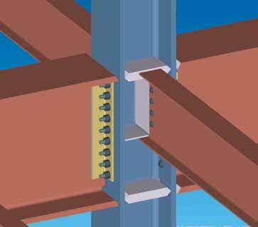
SDS/2 is the only system that provides true connection design — for individual members, as well as all interacting members in a structural joint.

FuLL Joint AnALySiS
Instead of choosing a connection from a library, SDS/2 designs the connection for you, based on parameters that you establish at the beginning of a project.
All connections SDS/2 automatically designs will comply with the connection design code standards the user chooses.
learn more
Want to see how simple it really is to design connections in SDS/2? Scan the QR code to watch SDS/2’s connection design in action.
Design ConneCtions
with SDS/2
compLete connection DeSign reportS
SDS/2 provides long-hand calculations of all designed connections, which simplifies the verification process. Scan the QR code to view an example of SDS/2’s automatically generated calculation design reports.
cLASh prevention
SDS/2 checks for interaction with other connections within a common joint. That means adjusting connections for shared bolts, checking driving clearances for bolts, sharing, adjusting and moving gusset and shear plates when required, and assuring erectablity of all members. All adjusted connections are automatically verified based on selected design criteria.


