15 minute read
Fastening Steel deck
InSIghtS
new trends, new techniques and current industry issues Steel floor or roof deck is only as good as its fastening. Whether it is the performance of the product as a diaphragm to transfer wind or seismic forces, resisting wind uplift, acting as a concrete form, providing bracing to beams or joists, or providing a safe working platform during construction, proper fastening makes the deck do its job.
What Choices Do I Have for Fastening Deck?
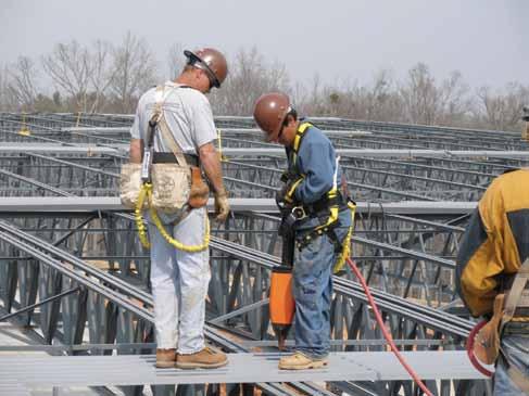
Traditionally, deck has been installed using welds for fastening to supports and button punches or welds for joining side-laps. However, over the past 30 years, mechanical fasteners such as screws, power actuated fasteners, and proprietary sidelap crimping devices have proven to be viable alternatives. When welding, it is essential that the finished weld penetrate into the supporting beam or joist, and that the puddle engage the deck on the weld perimFastening Steel Deck eter. The complete welding process usually requires 3 to 6 seconds, or perhaps longer on multiple deck thicknesses or thicker deck. This process requires a welder who is qualified to make these specific welds. Per By Thomas Sputo, Ph.D., P.E., AWS D1.3 Structural Welding Code – Sheet Steel, S.E., SECB arc spot welds can be made through multiple thicknesses of steel deck, as long as the total base metal (bare steel) thickness of the deck does not exceed 0.15 inches. Screws can be used for both fastening to supporting members and for fastening sidelaps. Typically #10 screws are used for sidelap attachment, and larger #12 or #14 screws are used for support fasteners. The drill points on these Thomas Sputo, Ph.D., P.E., S.E., screws vary in length depending on the total SECB, is the Technical Director thickness of the steel to be connected. Screws of the Steel Deck Institute, and a are installed using torque controlled drills consulting structural engineer with which allow for proper installation without the Gainesville, FL firm of Sputo overdriving and stripping the screw. Several and Lammert Engineering, LLC. manufacturers have developed “stand up” drilling equipment. Power actuated fasteners (or PAF’s) look similar to short nails that are driven into the supporting structure using either pneumatic pressure or powder cartridges. The driving process allows the fastener to penetrate the steel deck layer and fuses the fastener shank to the base steel supports. The force used for driving the PAF is varied depending upon the steel strength and thickness. Proper driving is ensured by following the manufacturer’s instructions, setting the power regulation on the installation tools, making trial fastenings and visual identification of the fastener head and washer conditions. These fasteners cannot be used for sidelap connections. Welds, screws and PAF’s can be combined; for instance, welds used for support connections and screws for sidelap connections, or in combination as part of a zoned steel deck diaphragm.
How Should I Choose a Fastening Method?
Generally, arc spot welded support connections are stronger and less flexible than mechanically connected support connections for both shear and uplift if the welding procedure is done properly. This may lead to needing a less dense fastening pattern for the deck, but there are pros-and-cons to be considered for each method. • Welding is a comparatively slower process and requires a higher level of skill.
Inspection requirements are more time consuming also, when compared to many mechanical fasteners. • Some screws and all power actuated fasteners are proprietary products with strengths and flexibilities unique to that product; therefore they cannot be generically specified. For deck sidelap connections, welded sidelaps are again stronger and generate less flexible diaphragm performance than screwed or button punched sidelaps, but the weld between the two layers of sheet steel at the side-lap can be difficult. While welded sidelap connections of 22 gage deck are permitted, their use is not recommended. Some proprietary crimped sidelaps have strength and stiffness equal to welds.
How Can I Fasten Deck More Economically?
On larger structures, consider zoning your roof deck connection design and select the fastening pattern to match the uplift and diaphragm demand which will vary across the floor or roof. Another way to provide for an economic yet well performing deck installation is to provide the deck erector with options. Installer preferences can vary regionally and should be considered. One way to accomplish this is to provide a fastening design that meets diaphragm and uplift requirements using generic welds and/or screws, and allow the deck installer to provide an engineered proprietary alternate connection method which meets strength and stiffness requirements. In order for the installer to provide an alternate, design requirements including zoned uplift (for roofs) and diaphragm strength demand needs to be provided. The loads need to be indicated as either ASD or LRFD, and noted if they are due to wind or seismic loading. Even if an alternate design is not permitted, this is important information to provide on the drawings.
What Should I Consider When the Deck is Loaded by Wind?
Anytime that deck fasteners are subject to both wind uplift and in-plane shear when loaded as a diaphragm, the combined tension and shear forces on the fasteners must be considered using interaction equations. A key point to remember is that if the shearwalls or other shear collectors are at the edges of the roof, this will combine the highest in-plane shear demand with the highest wind uplift pressures at the edge zones. Th e 2013 SDI Roof Deck Design Manual provides guidance on how to combine these forces.
How Can I Provide for Quality in the Fastening?
Th e SDI has developed the ANSI/SDI QA/ QC-2011 Standard for Quality Control and Quality Assurance for Installation of Steel Deck which provides requirements for steel deck installation quality (including fastening) in a mandatory format that can be used for inspection purposes. Th is Standard is incorporated by reference in Chapter 17 of the 2015 International Building Code, and is
Power actuated fastening. Courtesy of Pneutek, Inc.
available for free download from the SDI website (www.sdi.org). It is highly recommended that designers require compliance with the quality procedures in the standard through incorporation of the Standard in project specifi cations, even when special inspections are not required.▪
ADVERTISEMENT - For Advertiser Information, visit www.STRUCTUREmag.org
The BesT Thermal Thermal a anchor nchor on The markeT... ... Period Period

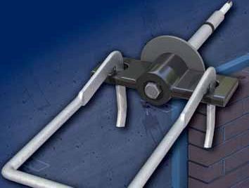
Through rigorous independent testing, 2D & 3D thermal imaging has proven that the 2-Seal™ Thermal Wing nuT is the most efficient thermal anchor on the market today. By combining a stainless steel barrel with a UL-94 encapsulated steel wing; heat transfer through insulation is reduced by up to one-seventh compared to other standard zinc barrels with snap-on plastic clips. is the most efficient By combining a stainless steel barrel with a UL-94 encapsulated steel wing; heat transfer thro compared to other
ugh

HoHmann & Barnard’s
2-Seal ™ Thermal Wing n nu uT T


toll free: 800.645.0616 www.h-b.com

Standard anchor thermal anchor
Thermal
Mass


Solutions

A Net Zero Energy Strategy with Structural Implications (and Opportunities)
By Bob Habian, AIA
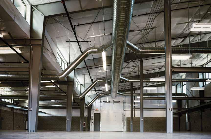
Figure 1. Partial height thermal mass walls connected to passive ducts for night time cooling. Courtesy of Guttmann & Blaevoet Consulting Engineers.
Figure 2. U.S. energy use by sector. Data source: US Energy Information Administration (2012).
The Jess S. Jackson Sustainable Winery building (JSWB) project team, led by Siegel and Strain Architects, set out to design a Net Zero Energy, LEED Platinum building, at the University of California, Davis, where summer temperatures exceed one hundred degrees on a regular basis. Concrete masonry, as seen in Figure 1, not only saved the day, but it opened the door for IDA Structural Engineers of Oakland, CA to take a more active role in energy optimization at the earliest stages of a project. climates like Davis, California, where there are high diurnal swings from hot to cold in a 24-hour period, exposed interior thermal mass, in the form of concrete masonry, can radically decrease the overall energy consumption. As shown in Figure 3, interior comfort is achieved using two primary strategies, time lag and damping. Insulation by itself can only achieve time lag. Th ermal mass, however, contributes to both time lag and damping. Achieving the proper balance of both is the shortest path to achieving internal comfort.
Energy Management is Mandatory Framed Structures Lack Suffi cient Mass
Th e production of energy is the leading contributor to carbon footprint and climate change and, in the U.S., the Building Sector consumes more energy than any other sector (Figure 2). In response, a number of stricter energy code requirements are being enforced across all building types. Th e cost of energy is rising and is a matter of growing concern for building owners. Th e JSWB project team set out to not only reduce their energy consumption, but together decided to reach a level of Net Zero Energy (NZE), in which the total energy consumed is off set by renewable energy production on site. Th e most important factor in achieving NZE is reducing the overall energy consumption to the lowest possible level.
The Basics of Thermal Mass
Th e goal of every building design is to achieve internal comfort regardless of outside temperatures. In Th e building industry in the Western U.S. has shown a long-standing preference for framed, insulated, low-mass buildings that shake and don’t fall down in earthquakes. A common belief in the west is that heavy mass buildings perform poorly in seismic conditions. Most often, the building failures referenced are unreinforced or poorly constructed. In addition, the historic abundance of wood has infl uenced our appetite for low mass, framed solutions. As a result, we traditionally rely on a combination of insulation and air handling systems to achieve interior comfort. To that end, most project participants believe the architect and the mechanical engineer are the only ones needing to be at the table to determine an optimal comfort strategy. As conventionally framed designs move in the direction of increased interior exposed thermal mass, the structural engineer becomes a necessary participant in the discussion.
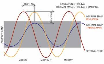
Figure 3. Time lag and thermal damping.
Finding the Right Balance of Thermal Mass and Insulation
After initially attempting to achieve NZE with a traditional metal frame building, in combination with an exterior skin of insulated metal panels, and a high degree of interior batt insulation, (R-59.6 in the walls and R-76 in the ceiling), the JSWB team determined that an insulation-only approach was simply not adequate to achieve NZE. And even though the exposed concrete slab did provide a fair amount of interior thermal mass, it did not offer quite enough to make a difference. The mechanical engineer, Guttmann & Blaevoet, of Sacramento, California, along with their in-house thermal mass expert, engaged a strategy of trying to achieve a classic balance of time lag (due to insulation), and temperature damping (due to thermal mass). After numerous rounds of modeling, the optimal blend of exterior insulation and interior, exposed thermal mass, was achieved simply by adding a partial height, solid grouted masonry wall, that was neither load bearing nor attached to the building envelope. This wall, in combination with the exposed concrete slab, achieved enough of a mass effect to allow the team to completely eliminate any need for a traditional air-handling unit for heating and cooling. The results of the modeling are shown in Figure 4. With exterior summer temperatures approaching 110 degrees, the interior holds to a steady range of 70 to 73 degrees.
So What Does NZE Mean for Structural Engineers?
OPPORTUNITY! Concrete masonry as a thermal mass component for energy optimization is a relatively misunderstood material to many mechanical engineers and architects alike. The proper integration of concrete masonry requires a careful review of the structural implications, particularly with respect to footings and connections to other structural elements in the overall project. And given the load bearing capacity and shear resistance of concrete masonry, there are many more options available today to integrate interior exposed thermal mass into the overall structural design. On this project, the structural engineer played an important role in determining the most cost-effective placement and configuration of the concrete masonry. The mechanical engineer undertook a specific effort to determine the proper amount of surface area and volume of masonry that would have the most impact on the energy model. The
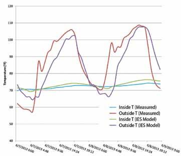
Figure 4. JSWB – temperature comparison. Courtesy of Chien Si Harriman.
– Chien Si Harriman, Guttmann & Blaevoet
structural engineer explored various configurations of the masonry and determined that a partial height wall with modest footing requirements was a more cost-effective placement than other options requiring larger footings. Additionally, it was the structural engineer that had to address how the overall system would function, the result of which was that the structural envelope would remain unattached from the concrete masonry. Together, the architect, mechanical engineer and structural engineer designed an ideal solution for reducing the overall energy requirement. On average, in the U.S., existing buildings account for 97% of the building stock, with only 3% being newly constructed, annually. In the western U.S., the majority of existing buildings are framed, insulated, and low mass, most of which could benefit from the addition of interior exposed thermal mass. So rather than simply competing for work on new construction, structural engineers have a tremendous opportunity to participate in the retrofit of existing buildings. And while most “energy retrofit” projects focus on high efficiency air handling systems, there is clearly a greater opportunity to reduce or even eliminate mechanical systems through the proper balance of insulation and interior exposed thermal mass. continued on next page
Integral-insulated CMU, also called Hi-R H block, as manufactured under license by Basalite Concrete Products LLC, is an innovation in the masonry industry that combines the best of traditional concrete masonry with an outboard insulation and interior exposed thermal mass solution (Figure 5). This system, when used as a load bearing, exterior envelope solution, integrates the best elements for energy optimization in a single-wythe, solid-grouted barrier wall. A trend toward thermal mass solutions will allow structural engineers to become early adopters of NZE strategies and to position themselves for significant project opportunities in new and retrofit construction, now and for years to come.▪
JSBW Project Team
Owner: University of California, Davis Structural Engineer of Record: IDA Structural Engineers, Inc.,
Oakland, CA Builder: Pankow Builders, Oakland, CA Architect: Siegel & Strain Architects, Emeryville, CA MEP Engineer and Energy Modeler: Guttmann & Blaevoet
Consulting Engineers, Sacramento, CA Concrete Block Producer: Basalite Concrete Products LLC,
Dixon, CA
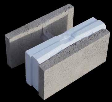
Figure 5. Hi-R H Integral Insulation CMU. Courtesy of Concrete Products Group.
Bob Habian, AIA, is a California licensed architect and leads Masonry Market Development for Basalite Concrete Products LLC in Dixon, California. He may be reached at bob.habian@paccoast.com.
ADVERTISEMENT–For Advertiser Information, visit www.STRUCTUREmag.org

Amy M. R. Trygestad Retires from STRUCTURE’s Editorial Board
Amy M. R. Trygestad, P.E., is stepping down as a member of the STRUCTURE magazine Editorial Board. Amy joined the Editorial Board in February of 2013 as a concrete industry representative. Amy is President and principal engineer for Chase Engineering in Minnesota. Chase Engineering is the local structural engineering partner with Thornton Tomasetti for the new 65,000+ seat Minnesota Multi-Purpose Stadium, currently under construction. Ms. Trygestad is an active member of the American Concrete Institute, serving on several ACI committees and as secretary of both 423–Prestressed Concrete and 421–Reinforced Concrete Slabs. Regarding her tenure on the Board, Amy commented, “I would like to express my sincerest gratitude for the opportunity to serve on the Editorial Board of STRUCTURE magazine. It has been a pleasure and privilege to work with contributing authors, fellow board members, and publishing staff to help produce this great industry publication.” Returning to the Board, Mike Mota, Ph.D., P.E., F.ASCE, F.ACI, is the Vice President of Engineering for the Concrete Reinforcing Steel Institute (CRSI). Mike is responsible for the Engineering Department and oversees the development of all technical publications and standards. Mike is an active member of several ACI and ASCE committees, including ACI 318 and 318 sub B and sub R. He’s Chair of ACI Committee 314 on Simplified Design of Concrete Buildings, and he serves on the Board of Directors of the Concrete Industry Board of New York City/NYC ACI Chapter. Jon Schmidt, P.E., SECB, Chair of the STRUCTURE magazine Editorial Board, had this to say: “I was sorry to see Mike go, and am very happy to have him back. I appreciate Amy’s contributions during the time in between, and wish her all the best.” Please join the STRUCTURE magazine Editorial Board in welcoming back Mike Mota!
ADVERTISEMENT–For Advertiser Information, visit www.STRUCTUREmag.org
Connect Steel to Steel without Welding or Drilling
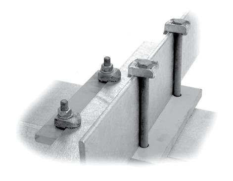
• Full line of high-strength fasteners • Ideal for secondary steel connections and in-plant equipment • Easy to install or adjust on site • Will not weaken existing steel or harm protective coatings • Guaranteed Safe Working Loads • Corrosion resistant
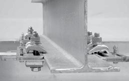
FloorFix and Grating Clip secure raised or open floors and grating. We manufacture ICCES certified BoxBolt® for HSS blind connections. FastFit universal kits for faster and easier steel connections.
NEW!
A KEE SAFETY COMP ANY


