
70 minute read
Advertiser Index


AZZ Galvanizing .................................. 15 Bentley Systems, Inc.............................. 29 Canadian Wood Council....................... 18 Cast ConneX......................................... 25 Computers & Structures, Inc. ............... 44 CSC Inc.................................................. 3 Design Data.......................................... 30 Devco.................................................... 12 Fyfe....................................................... 11 Integrated Engineering Software, Inc..... 20 The IAPMO Group............................... 27 KPFF Consulting Engineers.................. 32 NCSEA................................................. 13 New Millennium Building Systems......... 6 Notre Dame/Civil Eng. & Geo. Serv....... 8 Powers Fasteners, Inc............................... 2 RISA Technologies ................................ 43 S-Frame Software, Inc. ............................ 4 SidePlate Systems, Inc. .......................... 33 Simpson Strong-Tie............................... 21 Struware, Inc......................................... 17
PleAse suPPort these Advertisers
editorial Board
Chair
Jon A. Schmidt, P.E., SECB
Burns & McDonnell, Kansas City, MO chair@structuremag.org
Craig E. Barnes, P.E., SECB
CBI Consulting, Inc., Boston, MA Mark W. Holmberg, P.E.
Heath & Lineback Engineers, Inc., Marietta, GA Dilip Khatri, Ph.D., S.E.
Khatri International Inc., Pasadena, CA Roger A. LaBoube, Ph.D., P.E.
CCFSS, Rolla, MO Brian J. Leshko, P.E.
HDR Engineering, Inc., Pittsburgh, PA John A. Mercer, P.E.
Mercer Engineering, PC, Minot, ND Brian W. Miller
Davis, CA Mike C. Mota, Ph.D., P.E.
CRSI, Williamstown, NJ Evans Mountzouris, P.E.
The DiSalvo Ericson Group, Ridgefield, CT Greg Schindler, P.E., S.E.
KPFF Consulting Engineers, Seattle, WA Stephen P. Schneider, Ph.D., P.E., S.E.
BergerABAM, Vancouver, WA John “Buddy” Showalter, P.E.
American Wood Council, Leesburg, VA
Faculty Position in Structural Engineering
The Department of Civil and Environmental Engineering and Earth Sciences at the University of Notre Dame (http://ceees.nd.edu/) invites applications for a full-time tenure-track or tenured position in structural engineering to complement the existing faculty. Qualified candidates at all levels (assistant, associate, or full professor) will be considered, with hiring rank and tenure status commensurate with academic accomplishments. The successful candidate must hold a doctoral degree in an appropriate field and must demonstrate potential for high quality research and teaching. The existing faculty has significant strength in natural hazard risk mitigation and sustainable civil infrastructure. In accordance with these strength areas, the department is seeking an outstanding faculty member with a research focus on, but not limited to: infrastructure systems, high-performance and sustainable civil structures, reliability and performance of structures under extreme loading, innovative structural systems, computational mechanics, and foundation-structure interaction. Candidates for the position should be qualified to teach civil engineering courses, with a strong commitment to teaching excellence at both the undergraduate and graduate levels. The successful faculty candidate is expected to develop and sustain an externally funded research program and publish in leading scholarly journals. Applications should be submitted online at http://ceees.nd.edu/position-available as a single PDF with cover letter, detailed CV, statements of research and teaching, and names and contact information for three references. Review of applications will start immediately and continue until the position is filled. The University of Notre Dame is committed to diversity in education and employment, and women and members of underrepresented minority groups are strongly encouraged to apply. The University also supports the needs of dual career couples and has a Dual Career Assistance Program in place to assist relocating spouses and significant others with their job search. Inquiries related to this search can be directed to Dr. Yahya Kurama, Chair of the Structural Engineering Search Committee, at struct@nd.edu.
Advertising Account MAnAger
Interactive Sales Associates Chuck Minor Dick Railton
Eastern Sales Western Sales 847-854-1666 951-587-2982 sales@STRUCTUREmag.org
editoriAL stAFF
Executive Editor Jeanne Vogelzang, JD, CAE
execdir@ncsea.com
Editor Christine M. Sloat, P.E.
publisher@STRUCTUREmag.org
Associate Editor Nikki Alger
publisher@STRUCTUREmag.org
Graphic Designer Rob Fullmer
graphics@STRUCTUREmag.org Web Developer William Radig
webmaster@STRUCTUREmag.org
STRUCTURE® (Volume 19, Number 11). ISSN 1536-4283. Publications Agreement No. 40675118. Owned by the National Council of Structural Engineers Associations and published in cooperation with CASE and SEI monthly by C3 Ink. The publication is distributed free of charge to members of NCSEA, CASE and SEI; the non-member subscription rate is $65/yr domestic; $35/yr student; $90/yr Canada; $125/yr foreign. For change of address or duplicate copies, contact your member organization(s). Any opinions expressed in STRUCTURE magazine are those of the author(s) and do not necessarily reflect the views of NCSEA, CASE, SEI, C3 Ink, or the STRUCTURE Editorial Board.
STRUCTURE® is a registered trademark of National Council of Structural Engineers Associations (NCSEA). Articles may not be reproduced in whole or in part without the written permission of the publisher.
www.ncsea.com
C3 Ink, Publishers
A Division of Copper Creek Companies, Inc. 148 Vine St., Reedsburg WI 53959 P-608-524-1397 F-608-524-4432 publisher@STRUCTUREmag.org
Visit STRUCTURE magazine on-line at www.structuremag.org Visit STRUCTURE magazine on-line at www.structuremag.org Visit STRUCTURE magazine online at www.structuremag.org
inFocus new trends, new techniques and current industry issues The Social Nature of Engineering By Jon A. Schmidt, P.E., SECB
In order for engineering to qualify as a genuine example of what the ancient Greeks called praxis, it would have to satisfy at least two prerequisites: • It must be a predominately social form of activity, rather than a strictly technical one. • It must be pursued as an end in itself, rather than merely as a means to some other end. However, the reputation of the profession is such that most people would likely assume that it meets neither of these requirements. The common perception – even among engineers themselves – is that engineering is primarily a matter of technical problem-solving and design by solitary individuals, and that the chief function of an engineer is to devise the most efficient means to achieve an end that is specified by someone else. James Trevelyan, a mechanical engineering professor at The University of Western Australia, challenges the first of these misconceptions in a 2010 paper (“Reconstructing Engineering from Practice,” Engineering Studies, Vol. 2, No. 3, pp. 175-195). He instead characterizes engineering as fundamentally a “human social performance,” observing that it “relies on harnessing the knowledge, expertise and skills carried by many people, much of it implicit and unwritten knowledge. Therefore social interactions lie at the core of engineering practice.” Trevelyan’s research consisted primarily of interviews with and observations of “engineers in all major disciplines, experience levels, and types of business.” He was surprised to discover how frequently they were “relying on others to perform some work or provide information . . . These were mostly one-on-one situations with little or no formal authority . . . [which] led to the conclusion that securing willing and conscientious cooperation is an important part of coordination.” Separately, Trevelyan also surveyed 180 novice engineers and found that they spent about 60% of their time engaging directly with other people, a figure that is remarkably consistent with results from similar studies of seasoned veterans. Despite this, Trevelyan found that engineers persistently labeled tasks like performing analysis and preparing calculations as “doing engineering,” and generally marginalized other aspects of practice. This is important because “people tend to devote more effort to activities congruent with their current identity,” and engineering failures are usually the result of social breakdowns, rather than technical mistakes. Engineers constantly face time, information, and resource constraints, and thus must routinely make rapid and difficult choices in an effort to satisfy many diverse demands. In doing so, they confront not only the uncertainties inherent in nature and materials, but also the (often greater) unpredictability of their fellow human beings. This is precisely why engineering requires the exercise of practical judgment – not just theoretical knowledge and technical rationality, although those are also indispensable (“Knowledge, Rationality, and Judgment,” July 2012). In fact, engineering seems like a good candidate to serve as a paradigm example of a field that encompasses all three categories. The problem, as Joseph Dunne recognized (“The Rationality of Practice,” September 2012), is that modern societies are increasingly attempting to organize and regulate human behavior strictly in accordance with technical rationality – and engineering is by no means exempt from this trend. In response, Dunne asked an important rhetorical question:
In certain respects technical rationality seems to accord with the fabric of the material universe . . . However, does the attempt to impose it on the very different reality of human practices spring from a considered understanding of this reality itself, or from an a priori enthusiasm (even obsession) to have in these areas the same kind of standardisation and control which, partly through technical rationality, we have in our dealings with some aspects of the material universe? Dunne clearly leans toward the second option, and I am inclined to agree with him. The same subconscious desire may also explain why engineers largely relegate the social aspects of their professional lives to “non-engineering” status. Analysis and calculations clearly fall within our “comfort zone,” where we normally feel like we have a firm handle on things. The same is true even for more creative tasks like conceptualization and modeling. Dealing with people is a different story. In Dunne’s words, a person then encounters “volatile constellations of human passions and motivations” and “intervenes in a field of forces or immerses herself in a medium in which she seeks to bring about a propitious result.” Our actions are “inserted in a web of interaction, with its own power and limits conditioned by its capacity to mesh with – without manipulating – the actions of other agents.” Furthermore, “To acknowledge these points is to recognize the frailty and intricacy of human affairs – or, what amounts to much the same thing, the non-sovereignty of the single agent.” Along similar lines, Trevelyan describes the engineering enterprise as “a combined performance” carried out by a wide variety of stakeholders in which “the engineer’s role is both to compose the music and conduct the orchestra.” This is a helpful metaphor, because composers and conductors provide definitive guidance to those who actually play the instruments, but cannot directly dictate precisely how they do so once the baton is raised. Likewise, “an engineer has to ensure that everyone involved has sufficient understanding of the essential features that will create value to ensure that they are faithfully implemented and reproduced by other people.” Trevelyan’s last comment is interesting, because it implies that the engineer is the one who best knows how to “create value” and is then responsible for communicating this to “everyone involved” – again suggesting that engineering has a significant social dimension. What kind of value do engineers contribute in this way? I will begin addressing this question in my next column.▪
Jon A. Schmidt, P.E., SECB (chair@STRUCTUREmag.org), is an associate structural engineer at Burns & McDonnell in Kansas City, Missouri. He chairs the STRUCTURE magazine Editorial Board and the SEI Engineering Philosophy Committee.
Guest Column
dedicated to the dissemination of information from other organizations A recent session at the 2012 American Institute of Steel Construction North American Steel Construction Conference: The Steel Conference in Grapevine, TX explored the 2010 AISC Code of Standard Practice. Moderated by Glen Tabolt of STS Steel, the session featured the following speakers: Charlie Carter of AISC, Jim Stori of STS Steel, Kirk Harman of The Harman Group, Jim Larson of Phoenix Steel Erectors, and David Ratterman of Stites and Harbison, PLLC. The session also provided a look at what’s happening now in the AISC Committee discussions that will lead to the next edition of the AISC Code of Standard Practice. Following is a summary, and an invitation to comment and add to the discussion. The session from the NASCC is also available in free streaming media at www.aisc.org/2012nascconline; look for session N18. Committee, including: the National Council of Structural Engineering Associations (NCSEA), the Council of American Structural Engineers (CASE), the Structural Engineering Institute (SEI) of the American Society of Civil Engineers (ASCE), the American Institute of Architects (AIA), The Association of Union Constructors (formerly the National Erectors Association), the Steel Erectors Association of America (SEAA), and Arcom Master Systems (MASTERSPEC).
The 2010 AISC Code of A Brief History Standard Practice Charlie Carter spoke on the history of the Code, both recent and long-term. • It’s an AISC original, dating back to 1924. The Latest and Greatest This emphasizes how wise the founders By Charles J. Carter, Ph.D., S.E., P.E. of AISC were – they got it right in many respects at the start, proposing that the industry and design community would need standard design requirements (the AISC Specification), uniform contractual recommendations (the AISC Code of Standard Practice) and helpful guidance for design and construction (the AISC Manual). The Code and both of these other documents are still alive and carrying on today. • The Code has lived through many Charles J. Carter, Ph.D., S.E., revisions and five major rewrites. There are P.E. is Vice President and recommendations in the Code that date Chief Structural Engineer at back to the very beginning, but the Code the American Institute of Steel has changed with the times to continue in Construction in Chicago, IL. its role to reflect standard practices. He serves as Secretary of the • It has always been written as a default AISC Committee on the Code agreement for the buying and selling of of Standard Practice. fabricated steel. Alternative provisions, when needed or desirable, can be stated in the contract documents. • The Code was an industry-written document until the late 1990s. The Committee that wrote the 2000 Code of Standard Practice was broadened to include diverse and balanced representation of all stakeholders, including Architects, Engineers, CM/GCs, Fabricators, Detailers, Erectors, and one Attorney. The Code has very much become a collaborative effort since that time. • Many organizations and entities now have designated representation on the
Status of the Code
David Ratterman spoke about the nature and status of the Code. • The AISC Code of Standard Practice serves as a statement of trade custom and usage for the industry and design community. • Although AISC has not yet decided to formally submit the Code to the
American National Standards Institute (ANSI) for labeling as an ANSIaccredited document, AISC does follow the procedures used for the development of ANSI-accredited standards in the creation of the AISC Code of Standard
Practice. This means that consensus procedures are followed: all arguments are heard and all viewpoints are considered, with very stringent and specific voting rules to ensure that dissenting viewpoints are properly addressed and resolved. • The usual manner in which the Code becomes a part of the contract for a project is by incorporation of the Code by reference into the contract documents. This either can be done by the owner or design team, or by the fabricator as a part of the bid process. • When an issue is to be addressed by a court in a dispute, the Code likely will be used to interpret contracts that do not have specific provisions addressing the dispute – even if the Code is not referenced in the contract documents.
2010 Code Highlights
Jim Stori summarized recent revision of the Code, and highlighted some of the changes. • Sections 1.1 and 1.4 now provide a more general definition of “structures” – the definition includes structures that are not just buildings and bridges. • Section 1.2 has been updated to reflect current versions of the reference document listed. • Section 1.9, now provides general revisions on tolerances. Most notable, the commentary highlights that where no
specific mention of tolerance is made in the Code, it does not mean that the
Committee intends the reader to think this is a case where the tolerance is zero.
Rather, it is simply unspecified and the designers and constructors need to alert each other when a tolerance is needed. • Section 2.1 contains a few scope clarifications, such as base and bearing plates, loose as opposed to attached to the steel frame. • Section 4.7 now states that the erector should receive the erection drawings in a timely manner. • Section 6.4.3 has been clarified as to what is expected for incidental camber in trusses. • Section 7.10.2 Commentary expands on the information that should be clear in the documents so that the erector can better understand and perform the erection of a structure. • Section 10.2.5 has better definition of what’s required on an outside corner joint for AESS. • Section 3.1.2 was the most significant change in the 2010 Code.
It highlights SER responsibilities when connection design is delegated (types of loads, transfer forces required). It also highlights the fabricator’s responsibilities (submission of substantiating connection information and confirmation that the shop drawings are incorporating the connection designs). Commentary clarifies intent of the Committee. • Section 4.1 now has Commentary that describes the benefits of a pre-detailing meeting to discuss the project. • Section 4.4 has been updated to track and coordinate with changes in Section 3.1.2. Note that the approval process is still followed, each engineer (the SER and the connection engineer) is responsible for his/her own work, and the SER retains ultimate responsibility for the structure as a whole including connections. • The contract documents supersede the
Code of Standard Practice when they do not have the same provision or requirement (per the Scope statement in Section 1.1). • There is a specific list of what is included in structural steel (Section 2.1) and what’s not (Section 2.2). • There is a checklist of what should be on the structural drawings (Section 3.1). • There are defined processes for connection design work (Section 3.1.2). • The use of other drawings is permitted, but such use must be referenced in the structural drawings (Section 3.2). • The SER has final authority in a technical disagreement regarding connection design (Section 4.4). • Approval of a shop drawing starts a cost event – fabrication starts! (Section 4.4.1). • There is a system of specified tolerances within which a steel frame will be built (Sections 6 and 7).
What the Code Means to an Engineer
Kirk Harman spoke to the significance of the Code from his perspective as an engineer. His list of significant points included the following: continued on next page
What the Code Means to a Fabricator
• Section 4.2, my responsibilities as Jim Stori spoke to the significance of the Code a fabricator from his perspective as a fabricator. Key tabs • Section 5, mill materials and tolerances in Jim’s 1992 copy of the Code included: • Section 6, including fabrication and • Section 3.1, completeness of camber tolerances structural drawings • Section 10, defining what’s to be • Section 4.2.1, selection of connections expected when AESS is specified and responsibility for approval • Section 7.11.5, owner acceptance of • Section 7.2, what site conditions the frame fabricator can expect • Section 7.5.1, AB location tolerances What the Code • • Section 7.11, erection tolerances Section 7.11.5, owner acceptance Means to an Erector of the frame Jim Larson spoke to the significance of the The 2010 version was presented as more Code from his perspective as an erector. relevant to the marketplace today because • The Code provides for the steel it addresses issues the owner, the contrac- industry discipline from the average tor, the design professionals, the fabricator, erectors perception. the detailer, and the erector must all deal • It addresses things that all steel with. Key tabs in Jim’s 2010 copy of the erectors should be aware of for their Code include: performance and obligations. • Section 3.1, much expanded in • It outlines what other construction its definition of what’s required disciplines have the right to expect on structural drawings including from the steel erector. connection design delegation • The Code interfaces with other • Sections 3.5 and 4.6, related to AISC guidelines with regard to revisions and RFIs (didn’t even know steel erection, such as detailing, the term 20 years ago!)LGBeamer_5x4.75.pdf 1 10/9/12 9:44 AM fabrication and certification.
Only $499 LGBEAMER v8 Pro Cold-Formed Steel Design Software
Complete Modeling and Design of Steel Studs, Joists, Channels and Z’s Includes 2007 North American Specification Includes 2007 North American Specification (AISI S100) as Adopted in the 2009 IBC (AISI S100) as Adopted in the 2009 IBC Additional Design Features Additional Design Features
Framed Openings
Integrated Header, Sill and Jamb Design
HSS Sections
Square, Rectangular, Strong & Weak Axis
Floor Joists
Analyzes Six Load Cases including Alternate Span Live Load
Shearwall Design
Wood Sheathing, Gypsum Board and Steel Sheet
X-Brace Design
Straps 1 or 2 Sides, Chord Studs and Strap Connections
Roof Rafters
Multiple Load Cases, Pinch Axial Load
Phone: (541) 426-5713 x 301 301 Order Online at www.lgbeamer.com Downloadable demo, ordering & info on other available software
Current Technical Work on the Next Code
Charlie Carter summarized some of the work in progress for the next version of the Code of Standard Practice: • The Committee is attempting to write a guidance document for how to use existing features of the Code, and good practices to reduce the potential for extras and control variations in project costs. • The Committee is liaising with the
AISC Bender/Roller Committee to improve tolerances for curved members. • A guide on proper selection, specification and performance of camber is being discussed. • The Committee is working to clarify proper use of drawings other than the structural drawings to show work. • The Committee is looking at what a modern system of fabrication and erection tolerances might look like (and if that is any different than what exists now).
Challenges
David Ratterman finished the session with a summary of some challenges the Committee and AISC face: • AISC is evaluating the role of Code
Committee going forward. Traditionally, it has been limited to describing what can be stated as standard practice. There often are cases where practices are not standard, however. • To address such areas, the Committee may begin to develop guide documents of “best practices” that are companions to but not part of the Code. • The Committee is also seeking ways to address items that require faster, authorized updates and guidance – faster than the traditional cycle of publishing the Code every 5 or 6 years. • The Committee expects to tackle the challenge of how to resolve unauthorized amendments to the Code (those made in ways that violate AISC’s copyright).
Related, we will provide guidance on acceptable approaches to stating alternative requirements and procedures in the contract documents.
Questions?
The AISC Committee on the Code of Standard Practice welcomes input on the above information, and any other thoughts or ideas that you might care to share. Please send any correspondence to Charlie Carter at carter@aisc.org. ▪
Building Blocks
updates and information on structural materials
To facilitate the streamlined performance that is essential to large-scale wine production, massive fermentation tanks at a new facility in Livingston, California had to be supported at a height such that their contents could be rapidly discharged into a press at grade level. In addition to the significant seismic demand imparted on the structure by the tanks – which, when full, weigh up to 3,000 tons – other constraints specific to the wine-making process dictated the design, as did the client’s challenging schedule. The Owner engaged Summit Engineering to carry out a complete structural design in a time frame that would require completion of bid packages within six weeks and construction packages within three months. In addition to the rigorous design schedule, the new facility had to be ready to receive its first shipment of grapes within mere months of the award of the construction contract. This dictated the design of a structure that could be constructed quickly and efficiently in the field.Winery Supports its Liquid It was immediately clear that a steel-framed strucAssets on HSS and Cast ture was best suited to the application; however, the Steel Connections type of steel frame was based on a more thorough analysis of the Owner’s By Yi Yang, S.E., Jill Weinberg- requirements. The flexibility of a moment-resisting Huyette, E.I.T. and Carlos de frame would have been problematic with respect Oliveira, M.A.Sc., P.Eng to piping tolerances, and open perimeter bays were not a priority for the client. The choice, then, was between Ordinary Concentrically Braced Frames (OCBFs) and Special Concentrically Braced Frames (SCBFs). Selecting SCBFs decreased the seismic design loading significantly by allowing the use of a response modification coefficient R = 6, rather than R = 2.5 for OCBFs. This reduced foundation sizes and resulted in a significantly lighter and more economical superstructure. With the seismic force-resisting system selected, design could begin in earnest. Studying various construction scenarios revealed that field welding
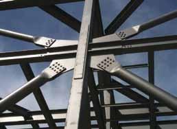
10.750- and 8.625-inch diameter braces equipped with Cast ConneX High-Strength Connectors framing into a “butterfly” gusset plate connection at the beamcolumn intersection. “Butterfly” gusset plate connection. The gusset plate is continuous through the column to accommodate the significant pass-through forces imparted to the braces during an earthquake; beams and braces are fieldbolted to the column.
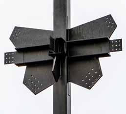
and the associated special inspection would impede the construction schedule. High-strength cast steel connectors emerged as an excellent solution for the SCBF connections. These connectors are configured to accommodate field-bolted installation of shop-fabricated brace-to-connector assemblies, thereby eliminating field welding at the brace-to-gusset connections. As the connectors accommodate double-shear bolted joints, their use results in highly compact gusset plate connections. By contrast, shear lag in conventional field-welded brace connections, where hollow structural section (HSS) members are slotted and reinforced, requires the use of significantly larger gusset plates. The high-strength connectors fit well with the design philosophy for this project, which capitalized on the simplicity of the connection details and ease of construction and maintenance. At first the Owner was hesitant, expressing some concern regarding the specification of a proprietary product. In addition, the testing and documentation that the connector manufacturer, Cast ConneX, had completed for ICC-ES certification of the connections was still under review during preparation of construction documents, creating some concern from the Merced County Building Department. However, both concerns were quickly put to rest, as representatives first worked with the design team to demonstrate to the Owner the significant cost and time savings that their connections provided, and then submitted ample permitting support documentation. Utilizing cast steel connectors also aided in expediting the design process, since the manufacturer provided standardized connection details in its design manuals, as well as customized connection detailing support. Early in the design, it became apparent that a larger size of brace would be required than was accommodated by the connectors available at the time. Cast ConneX developed a new size of high-strength connector – one to fit
10.750-inch outer diameter HSS – and was able to design and qualify the part in time for production for the project. This was in part because of the Owner’s willingness to engage the manufacturer in advance of the bidding process for the structural steel – a testament to the value that the connectors represented. Cast ConneX designs its cast steel connectors to accommodate round HSS brace members; the design team also selected HSS sections over wide flange shapes for the structure’s columns. HSS are the most efficient members for resisting not only axial loading, but also biaxial bending. In this project, several columns had to withstand loads from as many as three directions, so a symmetric section was ideal. HSS also lend themselves to consistent and repeatable detailing from both a design and construction perspective. Coordination with the tank manufacturers and the piping engineers was facilitated by the uniform sections of the frames; tolerances within the structure were critical as piping was to weave between the already compact configuration of the tanks. Finally, the design team recognized that the HSS column and brace sections would be easier to clean and maintain in service, which was important to the Owner since a winery is essentially a food production facility.
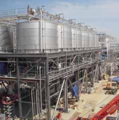
The new Special Concentrically Braced Frame (SCBF) structure at the winery, configured to support massive fermentation tanks at their second story.
Steel contractor Lloyd W. Aubry Company provided fabrication and erection services for the primary structural steel on the project. Cast ConneX provided technical support to ensure that the cast steel connectors were properly implemented, and the design team provided additional support with respect to erection sequencing in one tight area of the structure where braces had to be installed prior to a beam above. The result of this overall cooperative effort was a smooth process of erection;
ADVERTISEMENT - For Advertiser Information, visit www.STRUCTUREmag.org there was not a single RFI or change order generated in relation to the fabrication or installation of the braces fitted with the connectors. Eliminating costly and time-consuming field welding of the SCBF brace connections resulted in an efficient structure that met the schedule and budget constraints of the project.▪
Yi Yang, S.E. is a member of the Structural Engineering Association of California. Yi is currently a Principal and the Structural Division Manager at Summit Engineering in Santa Rosa, California. Yi may be reached at yi@summit-sr.com. Jill Weinberg-Huyette, E.I.T. graduated from California Polytechnic State University in San Luis Obispo, while serving as the New Member Chair and Secretary for the Cal Poly’s Student Chapter of SEAOC. She is a Structural Staff Engineer at Summit Engineering in Santa Rosa, California.Jill may be reached at jill@summit-sr.com. Carlos de Oliveira, M.A.Sc., P.Eng is president and principal structural engineer at Cast ConneX Corporation. The firm supplies both standardized and customized steel connector products. Carlos may be reached at carlos@castconnex.com.
Preserve Your Project Before It’s Even Built.
Galvanizing is Thinking Big Picture.
Hot-dip galvanizing with AZZ Galvanizing Services is the best way to ensure that your project will stand the test of time, saving money in costly maintenance repairs later. And since using eco-friendly zinc is less expensive than other corrosion barriers, the cost savings begin before the construction does — and will extend the life of the structure. Save money now and in the big picture.
azzgalvanizing.com
We Protect More Than Steel.
Structural DeSign
design issues for structural engineers Site conditions often dictate the engineering of long-span trusses for container cranes. Part 1 of this article (August 2012, STRUCTURE) included discussions on stress and fatigue, corrosion, dynamic impact allowance and the effect of dynamic impact on fatigue. Part 2 provides additional insight into torsional resistance, fracture critical connections and buckling analysis of built-up box elements. Other important issues discussed include methods of corrosion protection within ice fluctuation zones, and proposed deflection and camber criteria for long-span crane ways.
Truss Bearing and Torsional Resistance
The rotational restraint imposed on the bearing ends of a truss creates large negative moment, which can crack the deck and impose high tension cyclic loads in the deck over the support detail. The best solution Survival of a Crane Truss is to allow the truss support unimpeded rotation in a Waterfront Project (Figure 6). Deck beams supported by the crane truss must provide a restraint for top Part 2 chord rotation around its longitudinal axis (Figure 7). The deck beam connection to the crane girder By Vitaly Feygin, P.E. has to resolve the torsional moment imposed by the deck beam support reaction into the flexural moment action at the beam support. Fatigue longevity of such a connection is controlled by the magnitude of the built up plastic deformation. Plastic deformations occur only in the presence of shear stress. In a biaxial state of stress, the maximum shear stress, Vitaly Feygin, P.E. τ = (f1–f2) / 2 → 0 (Equation 5) (vfeygin.mic@gmail.com), is a principal structural engineer with Marine and Industrial Consultants, with offices in Jacksonville and Tampa. He is the author of two patents related to sea walls, composite cofferdams, bridge fenders and port structures. as the principal stresses f1 and f2 approach the same value. Biaxial tensile stresses tend to cause brittle failure, rather than plastic shear deformations. The state of biaxial stress can be aggravated by notches or other geometric discontinuities. Therefore, it is important to select weld designs and weld locations properly. The connection detail shown in Figure 7 falls under “Von Mises” criteria, described for plate design by:
The online version of this article contains detailed references. Please visit www.STRUCTUREmag.org. fy 2 = f1 2 + f2 2 – f1 * f2 + 3f 2 v ≤ Fy (Equation 6) where f1 and f2 are principal axial stresses, and fv is a shear stress. Obviously, the maximum shear stress (τ) approaches zero only when both axial principal stresses have the same sign and magnitude. Both principal stresses at the top plate of the connection are compression stresses, while those at the bottom plate have opposite signs. The connection detail described in Figure 7 prevents angular twist of the top chord of the truss. However, the
Figure 6: Truss bearing detail.
ability of the torsional supports to prevent angular twist comes at a price. Any restraint imposed on cyclic movement is prone to fatigue distress. Such connections should be carefully designed, in order to keep the stress range in the connection below the fatigue threshold limit. It is also good practice to keep intersecting welds away from geometric discontinuities, where forces normal to each other frequently reverse signs.
Buckling of Compression Elements and Fatigue
Some truss elements are subjected to large compression forces. Buckling of any of these elements leads to accelerated fatigue. That phenomenon was observed in the continuous span crane girders of steel mills, where tension field action (or truss action) led to accelerated fatigue of welds connecting the web to the flanges. Similarly, buckling of truss compression elements increases forces on elements in the tension stress range. It is extremely important to check all compression elements for local “lobe type” buckling. The present state-of-the-art is outlined in section E7.2 of the AISC 13th Edition. However, formulas in that section are based on a reduced effective width of the plate, which is based on the assumption that the total load is carried by strips adjacent to the supported edges (the box corners) of the buckled plate. Section E7.2 discusses post-buckling behavior of square and rectangular slender plates of uniform thickness. Such behavior is characterized
Figure 7: Crane truss torsional restraint.
by the number of lobes, or half waves, developing in the plate after buckling. As the load is increased, the edge stresses increase, but mid-width stresses decrease. Analytically, that behavior is approximated by selecting the total width of the strips, known as the effective width, such that the product of this width and the maximum stress in the plate is equal to the integrated product of the actual stress over the entire plate width. The plate’s ability to resist shear strain contributes to its postbuckling strength. Unfortunately, the AISC 13th Edition does not fully explain this concept; such behavior creates a useful resistance mechanism, but the designer must understand the limitations of such an approach. In particular, while post-buckling behavior can be used for the analysis of redundant systems, it should not be used for the analysis of nonredundant structures subject to cyclic loading. Original formulas for the strength analysis of circular tubes were based on test results restricted to elastic local buckling cited by Brockenbrouh and Johnston (USS Steel Design Manual ). A circular tube section with a thick wall usually fails in multi-lobe buckling, and is CRANE TRUSS TORSIONAL RESTRAINT FIG. 7 a preferable section for compression elements. The buckled form of the circular tube is unstable and cannot be used in the post-buckling mode. According to experimental test data, the local buckling stress for a circular tube is: fcr = 0.75fy + 0.016 Et / R (Equation 7) where R is the inside radius and t is the wall thickness. Test results confirmed that tubes with a slenderness ratio of fyR/(Et) ≤ 0.064 could be stressed to the yield point without local buckling. In circumstances where a circular tube section cannot be used as a compression element due to truss geometry, a rectangular box section is the next preferable section for a compression member. However, the rectangular box section tends to fail in a four-lobe buckling mode. The section with a larger number of lobes, or half-waves, is more stable and can resist a larger buckling force. One way to deal with that particular problem is to install properly spaced internal diaphragms, and check the plate between diaphragms for buckling from uniform compression loads. The rectangular box section buckles after the plate with the smallest stiffness begins buckling. The stiffness of the two adjacent plates, and the stiffening effect of the internal angle, delay the buckling of the whole box assembly. Plate theory provides a generic expression for rectangular plate local buckling in the elastic range: fcr = fy = kc π2D / (b2t) (Equation 8) where D = Et3 / 12(1- ν2) = plate flexural stiffness; ν = 0.30 = Poisson ratio in the elastic range; ν = 0.50 = Poisson ratio in the plastic range; t = plate thickness; b = plate width; and kc = buckling coefficient based on relative flexural stiffness of both plates. Brockenbrouh and Johnston provide modified local buckling coefficients, kw, based on the interaction of two adjacent long plates of a rectangular tube. Rectangular tube buckling in the plastic range (fcr ≥ 0.5fy) can be determined from: f ′ cr = fy – 0.25fy 2/fcr (Equation 9) The original formulas from the theory of plates cited in the USS Steel Design Manual have better defined boundaries and are more user-friendly. In that sense, the “old forgotten art” should be given due respect. Both Equations 8 and 9 represent nominal buckling strength. Appropriate resistance or safety factors should be applied to both formulas. c = 0.9 (LRFD) Ωc = 1.67 (ASD) Plate design for post-buckling behavior of built-up compression elements of the truss should not be allowed.
continued on page 19
The easiest to use software for calculating wind, seismic, snow and other loadings for IBC, ASCE7, and all state codes based on these codes ($195.00). Tilt-up Concrete Wall Panels ($95.00). Floor Vibration for Steel Beams and Joists ($100.00). Concrete beams with torsion ($45.00).
Figure 4 (from part 1): Crane truss elevation.
Additional Factors Affecting Fatigue Life
Residual Stresses and Lamellar Tear Welding, cutting, preheating, and any processes involving heat or deformation can produce high levels of tensile residual stress. Residual tensile stress decreases fatigue strength. Sometimes, the likelihood of brittle failure in the structure can be minimized by post-weld heat treatment, but the mechanical properties of the welded joints may be adversely affected. A suggested fabrication sequence for a box section with efficient fatigue resistance is shown in Figure 5. One of the most critical issues requiring the designer’s attention is related to welding details. Weldments prone to lamellar tear must be avoided. While it is impossible to avoid such potential behavior completely, the designer is urged to use prequalified, full-penetration welds as shown in the AISC 13th Edition.
Figure 5 (from part 1): Fatigue resistant box section for truss fabrication.
Grain Size Smaller metal grain size allows for longer fatigue life. Extensive heating increases the size of the metal crystals, reducing fatigue strength.
Internal Defects Weld porosity, non-metallic inclusions and internal shrinkage can significantly reduce fatigue strength. Therefore, all welds subjected to cyclic loading should be checked for porosity and internal cracks using advanced quality control methods. Weldments The designer of the truss is urged to develop a welding procedure that minimizes the number of assembly welds. The ideal assembly is shown in Figure 4 and Figure 5. The designer should realize that any additional welds will increase stresses caused by weld shrinkage. Intersecting or even parallel welds increase the likelihood of the so-called “banana effect” in built-up plate assemblies. The best way to control this phenomenon is to minimize the number of welds and avoid intersecting welds. It should be noted that sectional distortions have serious detrimental effect on fatigue life of the structure that cannot be analytically factored into the assembly design. Another highly important issue, frequently neglected by design professionals, is the selection of weld material. The weld materials should be neutral or cathodic against the base metal. A similar approach should be used for selection of bolts in bolted connections. The consequences of mistakes in selecting the right weld and fastener material can be extremely costly, and sometimes catastrophic. Fracture Critical Elements The crane truss is a non-redundant structure. Failure of any truss element has catastrophic consequences. All members of the truss having a stress ratio -1 ≤ R < 1 should be designed as fracture critical elements. Both, the AISC 13th Edition and the AASHTO LRFD manuals prescribe certain Charpy V-notch toughness requirements for weld and base metal materials in such members. However, it is prudent to use even more stringent toughness requirements than those currently prescribed by both codes. The Charpy V-notch impact test evaluates notch toughness, or the resistance of a specimen to fracture in the presence of V-shaped notches. The amount of energy required to fracture the specimen is used for plotting two curves: • Energy vs. Temperature • Percentage of Shear Fracture vs.
Temperature The temperature at which the percentage of shear fracture decreases to 50% is called the fracture transition temperature. The temperature at which the selected value of energy is absorbed (usually 20 ft-lb) is called the ductility transition temperature. The lower the transition temperature, the better the resistance to brittle fracture. Selected steel components must absorb a specified energy (E = 20 ft-lb) at the lowest expected operation temperature. The best material for structures subjected to high cyclic loads in an aggressive marine environment is ASTM A852 steel with Fy = 70 ksi, formerly known as COR-TEN B-QT (high strength, low alloy quenched and tempered steel).
Environment and Corrosion Protection Corrosion fatigue is a problem encountered by many marine structures. The best way to protect a submerged waterfront structure is to
prevent contact with the aggressive medium. Protection is especially important within the boundaries subjected to high abrasion and ice movement. A newly developed, highly alkaline modifi ed cementitious epoxy coating, Cemprotec E942, provides superior resistance to impact and water ingress. However, even the best paint will eventually peel off the steel due to ice abrasion and ice adhesion during high tide/low tide fl uctuation. Th e fact is, treatment of steel with a protective coating is always too little, too late and too expensive. What is the solution? Th e best way to deal with corrosion protection of steel within a zone of high abrasion is to prevent the coating from peeling off . Creation of a low friction zone around the steel within high tide/low tide depth solves that problem. Such treatment prevents direct ice contact with the painted surface and allows ice to slide up and down during the tide fl uctuation. Th e abrasion protection detail shown in Figure 8 effi ciently protects the paint on struts and diagonals from peeling off . UHMW-PE panels bolted to box and tube sections within the aff ected depth will prevent ice from adhering to steel elements. A fi nal line of defense for fully submerged steel can be provided by passive cathodic protection.
Figure 8: Abrasion protection detail within ice formation zone.
Open sections of diagonal joints at the truss top chord are highly susceptible to accelerated low water corrosion (ALWC). Th e best solution is to fi ll the annular space between the side plates of the open sections with expandable closed-cell foam, which prevents moisture retention and growth of sulfate-reducing bacteria.
Truss Camber Design
A crane girder or truss that spans more than 75 feet should be cambered for defl ection
ADVERTISEMENT - For Advertiser Information, visit www.STRUCTUREmag.org due to dead load (weight of the crane girder + attributed weight of the deck) plus half of the live load, including any load on the deck and the maximum load delivered to the girder from the wheels of the crane bogie. No impact factor should be included. Th e maximum vertical defl ection for a crane girder due to dead load and 100% of the live load is limited to L/1000. Girders or trusses with spans greater than 100 feet are designed with defl ections below L/1200. Larger defl ection creates severe traction problems, and leads to untimely rail or bogie wheel replacement.
Summary
Fatigue analysis is not an exact science, but rather an art based on statistical formulas and solid engineering judgment. However, it is an important and valuable tool for estimating the service life of a structure. Fatigue is a plastic damage accumulation. Signs of fatigue are frequently visible. Th erefore, it is highly important to identify all fracture critical connections, and schedule periodic inspections from early in the structure’s lifespan. Understanding the plastic damage accumulation concept will help the engineer design a cost-eff ective and long-serving structure.▪
Structural Software Designed for Your Success
Major Features


Easy to Learn and Use Analyze “Just about Anything!” Design: Steel, Wood, Concrete, Aluminum, and Cold-Formed Sketch, Generate, Import or Copy & Paste Models and Loads Link to Revit Structure Professional, Customizable Reports Building Code Support: IBC, ASCE 7, etc.
Visit www.iesweb.com
Download Your Free 30-Day Trial
IES, Inc. | 519 E Babcock St. Bozeman MT 59715 800-707-0816 | info@iesweb.com


We’re stacked in your corner.
If you’re planning to stack prefabricated shearwalls, make sure they’re Steel Strong-Wall® shearwalls. The Simpson Strong-Tie two-story solution is not only code listed, but can be installed right at the corner to save wall space. And since our engineered shearwalls are available in widths as narrow as 15 inches for stacked applications, you can design multistory homes with larger windows, doors and open spaces without sacrifi cing the high load values required for the project. To ensure your walls stack up, look to Simpson Strong-Tie for the widest selection of shearwalls code listed to the 2009 IBC (see ICC-ES ESR-1679). Visit www.strongtie.com/strongwall or call (800) 999-5099.

By Ahmad Rahimian, Ph.D., P.E., S.E. and Yoram Eilon, P.E.
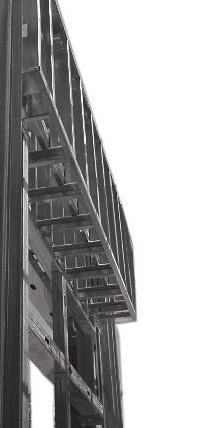
One World Trade Center (1WTC), currently under construction, is the tallest of the four buildings planned as part of the Ground Zero reconstruction master plan for lower Manhattan. It will also be the tallest building in the Western Hemisphere upon completion in 2013. The overall height of the tower from the ground level to the top of the spire reaches 1776 feet (541 meters) as a tribute to the “freedoms” emanating from the Declaration of Independence adopted in 1776. 1WTC, with its main roof at 1368 feet (417 meters) above ground, is designed to have the same height as the original towers. WSP Cantor Seinuk was commissioned by Silverstein Properties, the developer of the tower, as the structural engineer for the new One World Trade Center. In 2006, the Port Authority of New York and New Jersey, the owner of the World Trade Center, took over the development of 1WTC as part of an agreement with Silverstein Properties. The collapse of the Twin Towers on September 11, 2001 created a major debate in engineering communities worldwide with respect to the appropriate lessons to be learned and the need for mitigation strategies. Intensive studies were conducted for years after 9/11, including reports issued by the National Institute of Standards and Technology (NIST) in September, 2005, suggesting guidelines to be implemented in future standards. The design team, faced with numerous and unique challenges, paramount among them being security-related issues, was charged with the design of 1WTC and expected to meet or exceed future codes and standards that had not yet been published. For obvious reasons, many of the specific technical solutions and details will remain confidential. One World Trade Center’s program includes 3.0 million square feet of new construction above ground and 500,000 square feet of construction of new subterranean levels. The tower consists of 71 levels of office space, and eight levels of MEP space. It also includes a 50-foot high lobby, tenant amenity spaces, a two-level observation deck at 1,242 feet (379 meters) above ground, a “sky” restaurant, parking, retail space and access to public transportation networks.

Building Geometry
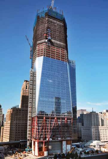
The building footprint above grade level starts with a 205-foot (62.5-meter) square plan. The office levels start 190 feet (58meters) above ground level, stacked over four levels of mechanical space above the main lobby. The four corners of the tower slope gently from the first office level inward until, at the roof, the floor plan again forms a square, but with a reduced dimension of 145 feet (44 meters), rotated 45 degrees from the base quadrangle. The elevation is formed by eight tall isosceles triangles creating an elongated Square Antiprism Frustum. At mid height of the tower, the floor plan forms an equilateral Octagon. The tapering of the building geometry reduces the wind effect on the tower. Generally, tall building designs in New York City are governed
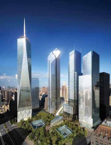
World Trade Center by day. Courtesy of Silverstein Properties.
by wind loads; however, this tower shape has an innate positive effect on the building performance under wind loading. Above the main roof at elevation 1368 feet (417 meters), a 408foot (125-meter) tall spire is designed to be mounted atop a thick reinforced concrete mat directly supported by the tower’s concrete core. Additional supports are provided via a multilayer circular lattice ring above the main roof, that are connected to the spire via a series of cables and supported by the main roof framing. The tower structure extends 70 feet below grade passing through four subterranean levels, where some of its structural components required repositioning to clear the Path train tracks that pass under the building at the lowest basement level.
Lateral Load Resisting System
The tower foundation is founded on Manhattan rock using spread and strip footings with bearing capacities of 60 tons per square foot or better. At selected locations, due to space constraints such as the proximity of the existing and operating train lines, it was necessary to excavate deeper into the rock in order to achieve a higher bearing capacity. Rock anchor tie downs extending 80 feet into the rock were installed to resist the overturning effect from extreme wind events. The below grade structure entails long span deep flat slab construction supported by reinforced concrete and composite columns spanning an average of 40 feet. WSP Cantor Seinuk was also commissioned to
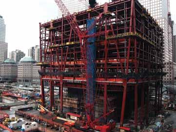
conduct an overall study of the stability of the World Trade Center site foundation wall and subterranean diaphragm slabs, the so called “bathtub” structure. The result of this study is incorporated into the design of the below grade spaces common to multiple stakeholders on the site. It required the introduction of auxiliary shear walls at below grade levels, positioned in strategic locations. The original slurry walls are reinforced by the addition of a liner wall directly supporting the below grade slabs. The below grade floor slabs are also designed to laterally brace the slurry walls as part of the long term “bathtub” stabilization strategy. The New Jersey Path Trains run through the West Bathtub where 1WTC is located. It was essential to keep the Path trains operational during the construction process; therefore, the constructability strategies became a primary consideration in the design of the below grade structure. Temporary structural steel framing was introduced and integrated into the permanent structure, bridging over the train tracks. The tower stability system, although enhanced by the below grade structure, was designed to be self-sufficient. The tower structure is comprised of a “hybrid” system combining a robust concrete core with a perimeter ductile steel moment frame. The reinforced concrete core wall system at the center of the tower acts as the main spine of the tower, providing support for gravitational loads as well as resistance to wind and seismic forces. It houses mechanical rooms and all means of egress. The core structure is compartmentalized with additional internal shear walls in orthogonal directions. The concrete strength ranges from 14,000 pounds per square inch (psi) to 8,000 psi from the base to the top. The walls are connected to each other over the access openings using steel link beams embedded into the concrete walls. A ductile perimeter moment frame system is introduced for redundancy and to further enhance the overall building performance under lateral wind and seismic loads. The perimeter moment frame wraps around all vertical and sloped perimeters, forming a tube system. Along the height of the tower, the tapering multifaceted geometry creates unique structural conditions which necessitated the design and fabrication of special nodal elements using relatively large plating with significant capacity for load transfer. For further enhancement of the lateral load resisting system, the concrete core at the upper mechanical levels is connected to the perimeter columns via a series of multilevel outrigger trusses in both orthogonal directions.
3D analysis model. Courtesy of WSP Cantor Seinuk. The floor system within the concrete core zone is a cast-in-place concrete beam and flat slab system. The floor area outside the core is concrete on composite metal deck supported on steel beams and connected via shear connectors acting as a composite system. At 1WTC, as in recent hybrid projects such as 7WTC (2006) and One Bryant Park (2009), the construction is sequenced by first erecting an all steel framing system throughout the floor, both inside and outside of the core, preceding the concrete core construction. The steel framing within the core is primarily an erection system which is embedded in the concrete core walls. The construction of the structure is staged in four highly orchestrated installation sequences of 1) steel framing, 2) metal deck and concrete outside the core, 3) concrete core shear wall, and 4) concrete floor construction inside the core. To facilitate the raising of the forms for the core walls, a ring beam was introduced at the outer face of the core in order to maintain a temporary gap between the floor system and the core wall allowing the forms to pass through. The total lag for the entire sequence is between 8 to 12 floors. Axial shortening, a consideration that must be accounted for in tall buildings, becomes even more important in hybrid structures due to the differing natures of the materials’ behavior.
Axial Shortening
Axial shortening studies were performed to identify the anticipated deformation of the concrete core wall and perimeter steel framing during and after construction. The elastic shortening of the steel erection columns at the core before encasement had to be carefully considered. The goal was that at the end of construction, the floors would be leveled and positioned at the theoretical elevations. In order to compensate for the shortening, the contractor could adjust the elevations of perimeter steel columns and the concrete core walls by super-elevating them to differing degrees. For the structural steel, this could be achieved by either fabricating the columns longer than the theoretical, shimming in the field during erection or a combination of both.
High Performance Concrete
The tower height and its slenderness imposed stringent demands on the overall strength and stiffness of the structure. In order to meet those demands in an economical way, high strength concrete of up to 14,000 psi was
Construction, March 2010. Courtesy of Joe Woolhead of Silverstein Properties.
utilized. For this project, 14,000 psi concrete was introduced for the first time in New York City. Research and experience have shown that a modulus of elasticity higher than values suggested by the American Concrete Institute (ACI) building code can be achieved by producing a high performance mix design specific to the project and site. Therefore, in addition to the strength, the modulus of elasticity of concrete was specified as a dual requirement. For 14,000 and 12,000 psi, the modulus of elasticity of 7,000,000 psi was specified. This contributes to the stiffness of the tower core wall, without the premium of specifying a higher concrete strength or increasing the thickness of the walls. The high strength concrete used for the thick concrete walls, defined as mass concrete, required a particular concrete mix to meet the most stringent of demands. To reduce and slow the heat of hydration, industrial by-products such as slag and fly ash were used to replace more than 50% of the cement content. This provided the additional benefit of helping the project meet the anticipated LEED Gold Standard.
Codes and Standards
From the onset, one of the main challenges was the selection of appropriate codes and standards for the design of the structure. The latest edition of the New York City Building Code at the time, which was based on the 1968 code with amendments, was used as the primary design code in combination with the Port Authority’s design guidelines. However, appreciating that it was essential to design this building with the most advanced standards available at the time, the International Building Code (IBC) 2003 structural provisions were adopted with respect to wind and seismic loading. The latest editions of the American Institute of Steel Construction (AISC) and ACI codes were adopted, particularly those regarding ductile design of the moment frame connections.
Wind Tunnel Testing
The structure has been designed for wind load requirements of IBC 2003, with due consideration of the New York City local wind climate conditions. In addition, a series of wind tunnel tests were performed to ascertain a more accurate measurement of wind loading and wind response of the tower with respect to hurricane wind load effects and human comfort criteria. High Frequency Force Balance (HFFB) and
Construction, June 2011. Courtesy of Joe Woolhead.
Aeroelastic tests, that are prevalent methods of wind tunnel testing for tall buildings to obtain overall wind loads and responses such as accelerations, were performed at the Rowan Williams Davies and Irwin Inc. (RWDI) wind tunnel facilities in Canada at different stages of the design. The aerodynamic and aeroelastic effects of the spire were also considered. The acceleration results at the highest occupied level meets the criteria of human comfort for office buildings. The structure is also designed for wind storms with a 1000 year return period, per IBC 2003.
Summary
As of mid-2012, construction of the tower has reached above the 100th floor and soared above the height of the Empire State Building. Completion of construction through the main roof is anticipated for first half of 2013. The design and construction of this project is the result of a relentless collaborative effort between numerous design and construction teams over a period of several years, resulting in creating an iconic tower reaffirming the preeminence of New York City.▪
Dr. Rahimian, P.E., S.E., F. ASCE is the Chief Executive of WSP Cantor Seinuk, based in New York and part of WSP Group PLC. In 2011 he was named to the Structural Engineer Magazine Power List and is the recipient of the 2007 AISC Special Achievement Award. Yoram Eilon, P.E. is Vice President at WSP Cantor Seinuk.

Landscape Evolution Observatory at Biosphere 2
Building Three Ships inside of a Bottle
By Allan Ortega-Gutierrez, P.E.
Biosphere 2, just North of Tucson, Arizona, has a new project in progress: Landscape Evolution Observatory (LEO), a science project from the University of Arizona that is changing the way nature is studied, while at the same time raising the bar for structural engineering challenges.
Description
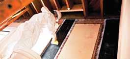
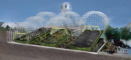
Th e project consists of three identical large steel planting tray structures built inside an existing glazed space frame building, a large greenhouse previously used for intensive agriculture, and supported over an existing concrete fl oor structure. Th ese steel structures have three main parts (Figure 1): 1) Th e tray is a 38-foot wide by 100-foot long (11.6 m x 30.5 m) steel box open on the top, sloping 10% in the longitudinal direction and changing the transverse slope along the tray’s length to form the ridges and valley channels that simulates a hill slope. To form this compound slope, the tray is structured with transverse U-shaped frame beams spaced at 1 meter on center, to match the sensor grid spacing resembling the ribs of a ship’s hull structure. All the transverse beams are attached to two deep longitudinal girders that connect to the substructure. Th e tray is clad on the bottom and all four sides with 3-inch deep steel N-deck, fi ber reinforced cement board and a special waterproofi ng membrane to contain a one-meter thick layer of a special soil made of crushed basalt, irrigation water and a complex array of 2,847 diff erent sensors. 2) Th e substructure is a system of steel columns, beams and steel braces that support the tray through ten load cells centered on the top of each column, 3) Th e personnel transporter is a mobile steel structure similar to a gantry crane that travels over the tray, covering the full width and length of it, and allows scientists to monitor and take samples of the experiment without disturbing the soil. Th ese three steel structures are unique in the world, in size and purpose, as they will simulate the interaction of the elements, especially water, with soil and vegetation on a hill slope. A special irrigation system and its supporting structure runs parallel to both sides of the tray, rising over 10 feet (3 m) above the top of the tray to support sprinkler heads that will simulate the eff ect of rain in various patterns.
Challenges
Each planting structure of LEO mimics a hill slope; several concepts were explored during the early design phases to achieve the desired surface slope. A steel structure with 16-gage N-deck was defi ned as the most cost eff ective based on the design loads and the diff erent slopes that defi ne the “hill”.
Substucture
Tray, shown with soil in place
Figure 1: Rendering of the LEO system showing its parts and the existing building partially opened to show the structures inside. Courtesy of University of Arizona School of Architecture/M3 Engineering and Technology.
Th e existing building introduced challenges with regard to space and the limited weight that could be carried by the current concrete structure, making the steel structure layout and optimization a priority. Th e layout of the structure using a steel tray and a braced substructure, is in response to these characteristics as well as a product of the selection of the load cells. Th e 10 steel columns of the tray frame were aligned directly over 10 concrete columns of the basement structure, thus eliminating bending loads on the concrete fl oor beams. Subsequent to the design phase, one more challenge presented itself: the access to the building. Th ere is only one direct entrance from the outside that measures 10 feet wide by 12 feet high. Th is demanded the design of several connections to be bolted for ease of fi eld construction, as well as set a limit on the size and weight of pieces that were transported to the construction site. Th e selection of load cells presented challenges, as the connection of the load cells needed to support the tray at an angle. Th e high axial loads in combination with the lateral load from the sloped tray reduced the options available in the market. Furthermore, one of the performance requirements set by the scientifi c group for the load cells was the ability to detect a change in weight equivalent to a layer of 1 cm of water (about 2 lbs/ft2) over the tray. All of these conditions required consultation with the load cell manufacturer, Honeywell, who provided a semi-customized set of load cells. Th e load cells are rigidly attached on the lower end to the column cap plates and have a self-centering pinned connection at the top, thus reducing the overall moment transferred to the load cell. Th e use of these load cells required tighter construction tolerances than standard steel construction, making the construction dimensional control more stringent. Working as the world’s largest weighing lysimeters (measuring devices that are used to measure the amount of water released through evapotranspiration) in addition to monitoring other parameters in the soil, these structures are subject to conditions that restricted the use of certain materials and required tighter tolerances during construction. For instance, any material in contact with soil or water inside the tray had to be tested by the scientist group in order to determine its eff ects on the experiment, leading the team to use materials such as fi berglass, polypropylene and special waterproofi ng membranes that could satisfy the complex conditions of loading and performance for such an experiment. Materials such as galvanized and stainless steels were prohibited from contacting soil or irrigation water, as they could aff ect the experiment. Nonetheless, the solutions were developed satisfactorily and construction started on time. Steel shop drawings were developed using Tekla® Structures as part of the design documents. Th is saved money and time during the construction phase, as the detailing complexity and any clashes were solved during the design phase. In addition, the model used to generate
the detailed shop drawings was used to quantify materials and helped the steel fabricator to understand the complex structures in a more efficient way before starting fabrication. The advantage of using BIM technology was reflected also in the reduced amount of RFI’s and field changes, given the complexity of the project. During the final phases of design, an additional concern was raised: can we fit LEO within the complex spatial configuration of the building? Laser scanning technology was used to recreate a model of the existing building and determine more accurately the available space, which helped enormously in finding possible clashes and redesigning areas such as the personnel transporter. Such technology allows the designer to improve the use of space, and reduce or eliminate costly modifications during construction. The personnel transporter idea started with a need to mobilize scientific staff over the experiment without affecting the soil or its content; however, no similar system had been previously used in such conditions. Many ideas were explored during this process and, finally, the use of window washing technology combined with industrial engineering expertise gave way to the current system, which provides a safe way to explore the contents of LEO.
Construction Realities
Despite the challenges, the project has progressed in a very positive and satisfactory way, in great part thanks to the team effort between all parts of the group, from the Owner to Designers, Vendors and Contractors. As a good example of this, during preconstruction, the contractor and steel fabricator proposed the addition of a jacking system to the structure to facilitate exchange of the load cells for temporary spacers once the soil was loaded. The original intent during design was to use
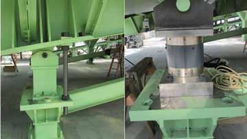
Figure 2: Jacking System (partially) and Temporary Spacer Installed (left) and Load Cell Installed (right). Courtesy of M3 Engineering and Technology.
the temporary spacers until the steel structure was placed in position; however, the contractor recommended using these until all welding was done to avoid affecting the load cells during the construction. The load cell, Jacking System and Spacer are shown in Figure 2. The project is in its final phase, finishing the construction of the third structure and putting the final touches on the second planting tray. More information may be found at the project website http://leo.b2science.org/, including three webcams that broadcast real time video of the LEO project.▪ Allan Ortega-Gutierrez, P.E. is a Structural Engineer at M3 Engineering and Technology and was in charge during the structural design and the construction administration phases of LEO. Mr. Ortega-Gutierrez can be reached at aortega@m3eng.com.
ADVERTISEMENT - For Advertiser Information, visit www.STRUCTUREmag.org
In-Model Review
The Next Step in Construction Administration
By Adam Azofeifa, P.E.
Building Information Modeling (BIM) has become progressively more popular as a drawing production tool in the last decade, to the point that engineers can now use software such as Revit® and Tekla® to not only create a set of drawings, but also develop a comprehensive model that can be combined with models from the architect, MEP, civil engineer, etc. to thoroughly coordinate the construction documents. Even 2D CAD drawings (for those team members not working in BIM) can be imported into BIM software and rendered for the purposes of clash detection and coordination. While the analytical capabilities of BIM software may not yet be where structural engineers would like it, hopes are high that it will be there soon. And we are fast approaching the day when building engineers no longer maintain archives with dusty rolls of (often incomplete or inaccurate) construction drawings, but rather a single comprehensive as-built computer model, where every component of the building is modeled right down to the light switches. With this ability to develop 3D models for comprehensive coordination and documentation, doesn’t it make sense that we also use modeling software as a review tool? The construction industry is currently in a state of transition when it comes to reviewing construction documents. The traditional path, where a sub-contractor submits multiple sets of paper shop drawings to the structural engineer for review, is becoming an exercise of the past. Some sub-contractors are now using BIM software to develop their shop drawings. And with ever more attention being focused on sustainability, the trend has shifted from delivering hard copies of those shop drawings to simply sending electronic versions. More advanced technology and mark-up software (e.g., Bluebeam® Revu®) enable drawings to be reviewed and stamped without plotting a single sheet. But why stop there? If the subcontractor uses a BIM model to develop its shop drawings, and the engineer has comparable modeling software available, we can cut out the shop drawings all together and engineers can simply review the fabricator’s model. This idea may seem unrealistic and maybe even implausible, but the fact is that software already exists that enables fabricators to send their 3D models to engineers for a complete review that takes place right in the model. Now the question is: can we and should we take advantage of that capability? This past year, the AISC Technology Integration Committee performed a survey of approximately 500 structural engineers to gauge their perspective on 3D in-model review. According to the survey, most engineers (roughly 90%) are using some form of paper or electronic (PDF or similar) drawings to review steel submittals, and less than 1% are using a true form of 3D in-model review. The survey also revealed that the majority of engineers felt that they either had the skills or the staff capable of performing an in-model review. At the same time, when asked if they thought an in-model review would save time compared to a paper or electronic drawing review, most engineers thought not. What this implies is that while many engineers feel they are capable of performing a 3D in-model review, given the opportunity, most would not choose that option. This revelation should not be surprising, considering that 24% of engineers surveyed also think that in-model review will never be the prevalent form of submittal review and shop drawings will always be required. Having recently performed a 3D in-model review of the steel structure for a large hospital project, I have an experienced perspective on the topic. I can say with confidence that the idea is not something to be dismissed. Not only did the in-model review significantly reduce review time compared to traditional shop drawing reviews, but the process also streamlined the communication of comments and revisions back to the fabricator and detailer. A 3D model enables the engineer to evaluate the structure (or subsection of the structure) as a whole, rather than a single member at a time. And the “intelligence” of the software enables an engineer to review and stamp several connections and members at once. This is the essence of Building Information Modeling – the elements in the model are not simply 3D renderings. Each element, from wide flange column to anchor bolt washer, has information embedded in it – the same information that one would see on a shop drawing, except now it can be viewed within the context of the structural assembly. Additionally, RFI’s, submittals, contractor notes, and the engineer’s comments can all be attached to the elements in the model. All relevant information is contained in one file that is easily stored, shared, and accessible. There are still several obstacles that stand in the way of 3D in-model review. BIM software has become so advanced that now even concrete reinforcement can be completely modeled, right down to the last stirrup, but the models become far too visually convoluted to be efficiently reviewed. Shop drawings tend to present the information more concisely when it comes to rebar. In addition, depending on the review software being used, an engineer’s review stamp cannot be attached to the model. Some software does enable an electronic signature or stamp to be embedded in the model, but sometimes the only evidence of an SEOR review is a report that is generated to summarize the review comments along with a stamped transmittal back to the contractor. A clear outline in the project contract of the expectations from a model review therefore becomes incredibly important. These issues and others indicate that perhaps, at least for the immediate future until in-model review software has been further developed, the best review methodology is a hybrid form that combines 3D in-model review and electronic shop drawings – the 3D model provides the engineer with all the benefits of BIM, and all the comments and stamps can be transferred to electronic drawings to serve as documentation of the review. As structural engineers, we have a responsibility to our clients to design safe structures and facilitate an efficient construction administration process. As we continually strive to improve our codes and design methodologies through research and advanced analysis and design tools, so should we aim to improve our construction administration practices with tools that increase efficiency and contribute to better quality control. Ultimately, our goal is to provide our clients with the best possible structures and to ensure that those structures are being constructed as designed. Any tool that helps us achieve that goal should be embraced. The construction industry is in a generation of technological transition. BIM has already exponentially improved our ability to communicate our designs. It’s time to take the next step.▪ Adam Azofeifa, P.E. is a Design Engineer at Degenkolb Engineers in Oakland, California. Adam is an active member of SEAONC (Structural Engineers Association of Northern California), and past co-chair of the SEAONC Younger Members Forum. He may be contacted at aazofeifa@degenkolb.com.
Understanding Professional Liability Insurance
Part 2
By Gail Kelley, P.E.
Part one of this article discussed general concepts related to professional liability coverage, including the insurer’s duty to indemnify (October 2012, STRUCTURE®). To indemnify means to compensate or protect from a loss. Under a professional liability policy, the insurer has a duty to indemnify the insured for covered losses, up to the limits of the policy. This second part looks at the insurer’s duty to defend, as well as common exclusions to coverage.
Claim Expenses
Expenses incurred in defending against a claim, referred to as either claim expenses or defense expenses, include the reasonable and necessary fees charged by an attorney. Many policies give the insurer the right to designate the attorney; some policies allow the insured to select the attorney, subject to the insurer’s approval. Claim expenses also include the other fees and expenses that result from the investigation, defense and appeal of a claim, if incurred by the insurer, or by the insured with the prior written consent of the insurer. Most types of liability insurance, including CGL policies, do not apply claim expenses to the policy limits. In contrast, professional liability policies are typically “wasting policies” which means that claim expenses are deducted from the policy limits. Both the insurer’s duty to defend and its duty to indemnify terminate when the applicable policy limit is exhausted, whether or not the claim has been resolved.
Duty to Defend
The insurer must defend any claim covered by the policy, even if the claim results from groundless or fraudulent allegations. The insured must provide the insurer with all information, assistance, and cooperation that the insurer reasonably requests. In addition, the insured cannot do anything that prejudices the insurer’s position or its rights of recovery. In particular, the insured cannot settle a claim or admit liability without the insurer’s consent. The insurer is not liable for any settlement, assumed obligation, or admission to which it has not consented.
Settlement
Likewise, the insurer cannot settle a claim without the insured’s consent. However, if the insured refuses a settlement that is acceptable to both the claimant and the insurer, the policy may limit the insurer’s liability to the amount for which the claim could have been settled, plus the claim expenses incurred until the date of the refusal. Likewise, if the insured requires the insurer to appeal a judgment that the insurer would not otherwise have appealed, the policy may limit the insurer’s liability to the lesser of the damages awarded in the judgment or the appeal. The insured is responsible for any increase in damages (including interest, attorney fees and costs). Insurers will often provide an incentive to encourage the use of mediation to settle claims. As an example, the policy may state that if the insured settles a reported claim though mediation, the insurer will reduce the deductible for that claim. The fact that defense costs are applied toward coverage limits is another incentive to settle a claim rather than allow it to go to litigation or arbitration.
Subrogation
As is typical with insurance policies, professional liability policies will usually state that the insurer is subrogated to the insured’s right of recovery for any payment made under the policy. Subrogation means that the insurer “steps into the shoes” of the insured and acquires any rights the insured has with respect to the payment. For example, if the A/E’s insurer was required to pay an adjacent land owner for damage caused in part by the owner, the insurer could sue the owner for reimbursement. The insured must do whatever is necessary to secure and preserve the insurer’s rights, including signing any documents needed for the insurer to effectively sue in the name of the insured. It has become common for participants on a construction project to waive their right of subrogation against other participants, however. As a result, most E&O policies state that the insurer waives its rights of subrogation against clients of the insured, but only to the extent required by a written contract. A/Es should ask their insurance brokers to review their standard client contracts to ensure that the subrogation requirement in their policy does not conflict with any provision in their contracts.
Exclusion for Fraudulent and Intentional Acts
E&O policies only cover claims for negligence, where negligence is defined as failure to comply with the standard of care applicable to the insured’s professional services. Policies do not cover claims arising out of intentional acts, whether committed by the insured, at the insured’s direction, or with the insured’s prior knowledge. In addition, they do not cover claims arising out of fraudulent, malicious, or criminal acts. Notwithstanding these exclusions, the insurer will generally pay expenses for such claims, as long as they arise out of the provision of professional services, unless there is finding that the insured’s act or omission was fraudulent, malicious, criminal, or intentional. If there is such a finding, the insurer’s liability for claim expenses ceases and the insured must generally reimburse the insurer for any claim expenses it has paid. A finding is deemed to occur upon a criminal conviction for the acts or omissions forming the basis of the claim, or a judgment in a trial court against the insured.
Other Exclusions
Professional liability policies typically exclude coverage for claims that are more properly covered by other types of insurance. Thus they exclude coverage for liability arising out of the insured’s ownership, operation, or use of property or any kind of vehicle. They also exclude coverage for liability arising out of the sale or distribution of any product developed by the insured.
Likewise, policies typically exclude claims arising out of any type of alleged discrimination, as well as liability arising out employment-related practices, including refusal to employ any person or termination of any person’s employment. Claims for workers’ compensation under any workers’ compensation, unemployment compensation, or disability benefits law are also excluded. An E&O policy will cover claims alleging that the insured’s professional services are not in conformity with the applicable standard of care, as this is the definition of negligence. It will not cover any other express warranties with respect to the insured’s services, however. For example, it would not cover a claim based on the insured’s failure to complete work by the agreed-upon date, because that would be a breach of contract, not negligence.
Supplementary Payments
Many E&O policies reimburse the insured for legal fees and expenses if a regulatory or administrative action is brought against the insured based on its performance of professional services. Such actions are usually brought under the Americans with Disabilities Act (ADA), the Federal Fair Housing Act (FFHA), or the Occupational Safety and Health Act (OSHA). Some policies also reimburse reasonable legal fees and expenses if a disciplinary proceeding is brought against the insured. A disciplinary proceeding means a proceeding by a regulatory agency to investigate charges of professional misconduct in the performance of professional services. Although these reimbursements generally do not have a deductible and do not count against the coverage limits of the policy, the maximum amount reimbursed is typically much lower than the coverage limits. In addition, the insurer will not pay any damages, fines, or penalties pursuant to an administrative action or disciplinary proceeding. Most policies will reimburse the insured for loss of earnings and travel expenses if the insured has to take time off from work to attend mediation meetings, arbitration hearings, depositions, or trials relative to a claim. The insured is typically not compensated for any other time spent in assisting in the defense and investigation of a claim.

Seattle Everett Tacoma Lacey Portland Eugene Sacramento San Francisco Walnut Creek Los Angeles Long Beach Pasadena Irvine San Diego Boise Phoenix St. Louis Chicago New York Abu Dhabi, UAE Professional liability policies are usually written such that coverage is in excess of any other valid insurance available to the insured, including any project-specific insurance. This includes policies carried by parties other than the insured. Coverage does not start until the limits of any other policy have been exceeded.
Additional Insureds
Owners often ask to be included as additional insureds on an A/E’s CGL policy, as this provides them with coverage for claims by third parties, such as tenants, that arise from the A/E’s work. However, most professional liability policies exclude coverage for claims by another insured (“insured versus insured claims”). Thus, it does not make sense for an owner to be named as an additional insured on a professional liability policy, since the policy would not cover the owner’s claims for design defects.
Conclusion
An insurance policy is a contract between the insured and the insurer. Most professional liability policies contain an integration clause that limits the contract to the application and the policy. Typical wording for such a clause is: The Insured agrees that this Policy, including the Application and any endorsements, constitutes the entire agreement between the Insured and the Insurer. It is important that an A/E read its policy documents carefully so that it understands its rights and obligations. When deciding whether to purchase professional liability insurance, an A/E should compare the policies offered by several different insurers, to see which policy best fits its needs.▪
Gail S. Kelley, P.E. is a LEED Accredited Professional as well as a licensed attorney in Maryland and the District of Columbia. Ms. Kelley is the author of Construction Law: An Introduction for Engineers, Architect, and Contractors, published in 2012 by John Wiley & Sons.


