
9 minute read
Modern limit analysis tools for reinforced Concrete Slabs


Technology
information and updates on the impact of technology on structural engineering
At a recent workshop, organized by the University of Sheffield in association with LimitState and held at the IStructE Headquarters in London, the authors of this article presented new computational tools for the limit analysis of reinforced concrete (RC) slabs. The workshop was attended by practising engineers from different fields, including those involved with the design of RC slabs and those with an interest in the assessment of existing RC slabs for changing service loads. The computational tools presented align closely with the traditional methods of designing and assessing RC slabs. The traditional method for assessing slabs has been Johansen’s yield line technique which, as an upper-bound method, relies for its accuracy on the ability of the engineer to postulate a realistic collapse mechanism. LimitState:SLAB uses the discontinuity layout optimisation (DLO) method, robustly and efficiently computerising the yield line technique, automatically identifying collapse mechanisms Modern Limit Analysis that have corresponding collapse loads very close Tools for Reinforced to theoretical solutions Concrete Slabs (typically within 1%). In contrast, the traditional method for designing slabs has been Hillerborg’s strip By Angus Ramsay, M.Eng, Ph.D., method, which, as a lower-bound method, C.Eng, FIMechE, provides a set of equilibrium moment fields Edward Maunder, MA, DIC, that may be used to size and position the Ph.D., FIStructE and reinforcement. Ramsay Maunder Associate’s Matthew Gilbert, B.Eng, Ph.D., (RMA) equilibrium finite element software, C.Eng, MICE, M.ASCE, RMA:EFE, robustly and efficiently automates this approach to provide a complete equilibrium moment field (which includes torsional moments) with a corresponding collapse load very close to the theoretical solution. When used together, LimitState:SLAB and RMA:EFE lead to accurate plasticity solutions (typically within 1 or 2% of each other) that completely define the limit solution in terms of collapse mechanism (LimitState:SLAB) and moment fields (RMA:EFE). The efficiency of these solutions can be measured in the time taken to solve, typically no more than a few seconds. Modern limit analysis tools such as RMA:EFE and LimitState:SLAB, when used in combination, provide the practicing engineer with a way of verifying the solutions (and of ensuring simulation governance), i.e. the engineer can sleep soundly at night knowing that the collapse load has been predicted with good accuracy (since when lower and upper bound solutions agree, the true solution has been found). In the absence of a verified solution, the engineer using the yield line method needs to rely on his or her good judgment to determine a realistic collapse mechanism. The engineer might also be tempted to rely on anecdotal evidence that inherent membrane action within the slab will increase capacity beyond that derived by consideration of flexural strength alone, and/or advice offered by professional bodies that, for example, yield line solutions are generally no more than 10% above the true value [1]. Neither of these, of course, would stand up to a great deal of scrutiny without further verification or validation work. In a recent article [2], a solution to a problem published by the first author in 1997, [3], was presented and used to demonstrate how yield line computations have developed over the last 20 years. Although the original published result was not intended as an exact solution, it now turns out, using modern limit analysis tools, that the collapse load was 40% above the theoretical value! While it is clear that experienced engineers might not have accepted the solution provided in the original publication, it is considered to be useful to less experienced engineers working in this field to document an example where the yield line method has produced an extremely unsafe result. The problem is defined as the Landing Slab Problem and automated methods using meshes of triangular elements together with geometric optimisation are used to demonstrate the state-of-art from the 1990s.
The Landing Slab Problem
This problem involves a reinforced concrete landing slab typical of the type found in the stairways of modern buildings. It is a two-way slab in that significant moments are developed in both directions. The slab is simply supported on three adjacent
The online version of this article contains detailed references. Please visit www.STRUCTUREmag.org.
sides, and the reinforcement at the top and bottom of the slab provides equal isotropic moment capacity (m). Th e slab is loaded with a uniform distributed load (q) (the loading arrows are placed at the centre of the corresponding slab portion) as shown in Figure 1, and has a unit load to strength ratio (q/m).
(a) (b)
The Automated Yield Line Technique

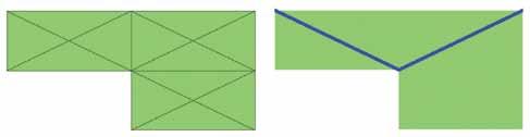
In the 1997 work, the mesh shown in Figure 2 was used. Th is led to the collapse mechanism shown with blue lines, representing element edges where the moment has reached the sagging capacity of the slab and with the symbol λ representing the load factor. An analysis of a more refi ned mesh in 2011 produced the following results shown in Figure 3. Th is result indicates that the 1997 solution was not correct – the yield lines, while emanating from the corners of the slab, do not terminate at slab corners. Th is sort of yield line pattern, which now involves red lines where the hogging capacity of the slab has been reached, appears to provide a qualitatively reasonable representation of the way in which the slab might crack. continued on next page
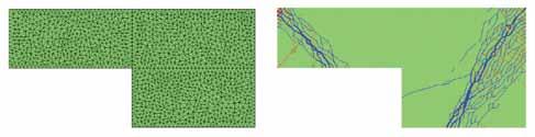
Figure 2. Results from the 1997 Research ( λ = 5.86). a) Mesh; b) Yield line pattern.
Figure 3. Results from the 2011 Research (λ = 5.47). a) Mesh; b) Yield line pattern.
Figure 4. Results for a coarse unstructured mesh from EFE ( λ = 4.38). a) Mesh; b) Yield line pattern.
(a) (b)
(a) (b)
ADVERTISEMENT–For Advertiser Information, visit www.STRUCTUREmag.org
The BesT Thermal Thermal a anchor nchor on The markeT... ... Period. Period.


Through rigorous independent testing, 2D & 3D thermal imaging has proven that the 2-Seal™ Thermal Wing nuT is the most efficient thermal anchor on the market today. By combining a stainless steel barrel with a ul-94 encapsulated steel wing; heat transfer through insulation is reduced by up to one-seventh compared to other standard zinc barrels with snap-on plastic clips and reDuceS inSTallaTion laBor By up To 50%.
HoHmann & Barnard’s
2-Seal ™ Thermal Wing n nu uT T


toll free: 800.645.0616 www.h-b.com
Standard anchor thermal anchor
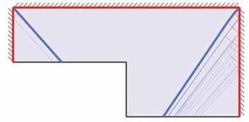
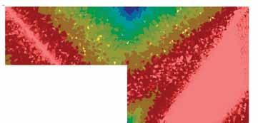
Figure 5. DLO Solution of 2014 using 4000 nodes ( λ = 4.21). Figure 6. RMA:EFE Solution of 2014 using 2484 elements ( λ=4.20).
Geometric optimization of the mechanism indicated by the 2011 research is shown in Figure 4 (page 13).
Modern Limit Analysis Tools – LimitState:SLAB
The results produced by the DLO-based software LimitState:SLAB [4] are in the form of yield line patterns with the same convention as already described for color and thickness of the yield lines (Figure 5). Note however that whereas the yield lines in Figures 2, 3 and 4 were based on moments, those in Figure 5 are based on rotation (hence the red lines on the supported boundary in Figure 5). This yield line pattern is similar to the geometrically optimized pattern of Figure 4 in terms of the dominant yield lines. However it shows additional yield lines that point to a more complicated collapse mechanism for the slab, with more distributed yielding than suggested in Figure 4. The load factor from the DLO method is 4% lower than that of the geometrically optimized solution already presented.
Modern Limit Analysis Tools – RMA:EFE
RMA’s software tool (RMA:EFE) [5] provides a solution to this problem in terms of equilibrium moment fields. A method of demonstrating that these fields do not violate the yield criteria is to consider the utilization ratio. The utilization ratio, which compares the moment field with the moment capacity or yield moment, can be calculated at points in the model as the degree to which the local moment field can be scaled up before it causes yielding. Such a plot is shown for the landing slab in Figure 6, where the contour colors range from zero (blue–unutilized) to unity (red – fully utilized). The regions where the material is fully utilized correspond well with the yield line pattern of Figure 5. With upper-bound (LimitState:SLAB) and lower-bound (RMA:EFE) solutions to this problem available, the theoretically exact collapse load can be predicted within very tight bounds: 4.20 ≤ λ ≤ 4.21 The load factors are within 1% of each other and thus give an extremely accurate prediction of the theoretically exact value. Erring on the side of safety and using the lower-bound load factor in the calculation shows that the published result of 1997 was 40% too high!
Practical Conclusions
This brief article has shown how limit analysis, particularly the yield line technique, has developed over the last 20 years, and has led to modern computational tools for the practicing engineer that are able to bound the theoretical solution to very close tolerances thereby providing strong simulation governance in the design/assessment of reinforced concrete slabs. There is now no need to rely on rules of thumb, such as the ‘10% rule’, or arguments that any over-estimate of capacity through a coarse yield line analysis will implicitly be accounted for by membrane action (which for a given slab may in reality not be present). Also noted in the recent workshop, elastic techniques are increasingly being used in the design of new RC slabs but, as a result, reinforcement over columns becomes significantly greater than indicated to be required when using a limit analysis based approach. The availability of efficient and robust software for predicting the collapse load of reinforced concrete flat slabs now means that one of the original outcomes of the European Concrete Building Project, to encourage engineers to design slabs based on limit analysis techniques [6], can now safely be realized and applied with confidence to both conventional and more complicated and novel slab configurations. RMA and LimitState encourage engineers practicing in this field to get involved by using and driving the future development of these software tools for their own commercial advantage.▪
Angus Ramsay, M.Eng, Ph.D., C.Eng, FIMechE, is the owner of Ramsay Maunder Associates, an engineering consultancy based in the UK. He is a member of the NAFEMS Education & Training Working Group and acts as an Independent Technical Editor to the NAFEMS Benchmark Challenge. He can be contacted at angus_ramsay@ramsay-maunder.co.uk. Edward Maunder, MA, DIC, Ph.D., FIStructE, is a consultant to Ramsay Maunder Associates and an honorary Fellow of the University of Exeter in the UK. He is a member of the Academic Qualifications Panel of the Institution of Structural Engineers. He acts a reviewer for several international journals, such as the International Journal for Numerical Methods in Engineering, Computers and Structures, and Engineering Structures. He can be contacted at e.a.w.maunder@exeter.co.uk. Matthew Gilbert, BEng, Ph.D., C.Eng, MICE, M.ASCE, is Professor and Director of Research in the Department of Civil and Structural Engineering at the University of Sheffield, UK. He is also the Managing Director of LimitState Ltd, a software company set up to make numerical methods developed in the University available to a wide audience. He can be contacted at m.gilbert@sheffield.ac.uk.
A similar article was published in Concrete Magazine (July 2015). Content is reprinted with permission.


