10 minute read
Structural Connections
Anatomy of a Mass Timber Bearing Intersection
By D. Scott Nyseth, S.E., and Jason Smart, P.E.
Proper design of bearing intersections between mass timber members is critical to the overall success of a mass timber project. e details of these intersections have a signifi cant eff ect on cost and schedule. is article focuses on the multi-story column condition, where loads from the column above need to be transferred down through the beam-column intersection, and the beams are supported using a bearing pocket instead of a bearing hanger (Figure 1).
Constructability Column Load Transfer
When initially installed, cambered beam ends may need special cuts to allow them to sit tight in the bearing pocket. Sealing/protecting ends of beams and columns is critical because the ends of these members have the potential to absorb water if wetted during construction, causing swelling and damage to the intersection. Computer Numerical Control (CNC) tolerances are small for most cuts, copes, and drillings (⁄16 to ⁄8 inch); however, they are larger for longer slots that need to be cut for items such as knife plates (⁄8 to ¼ inch or more). CNC machine tooling for preparing beam pockets and tenons are typically round cutting bits; therefore, the resulting surfaces will have rounded surfaces that need to be addressed in the design. In the absence of a diaphragm, beam-column intersections should have some lateral capacity for bracing and racking loads during erection and for leveling and plumbing of the beam-column frame. Column stability is crucial for projects that use a concrete diaphragm instead of a Cross-Laminated Timber (CLT) diaphragm. In this scenario, multiple stories of columns, beams, and fl oors can be erected before the structural diaphragms are in place. is requires special design attention, especially at exterior columns. In addition, the contractor needs to provide additional shoring for these columns to stabilize the structure until the concrete diaphragm is in place.
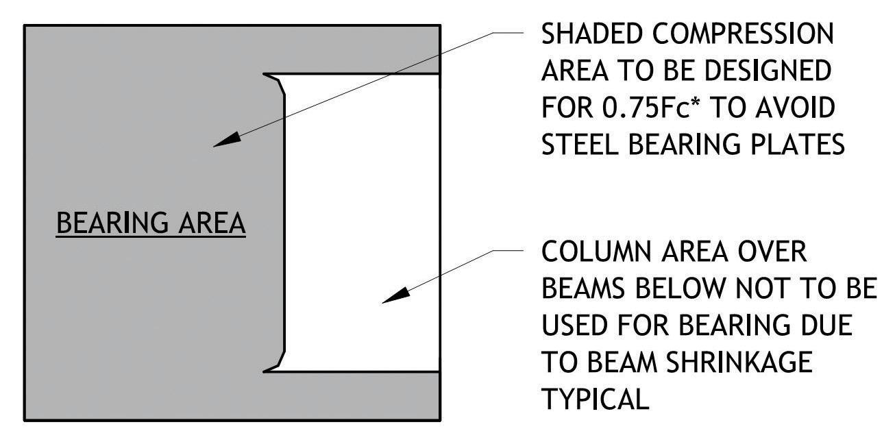
For maximum bearing capacity, wood columns should bear directly on wood columns end-to-end because wood is strongest when bearing parallel to the grain. For example, if a wood column were to bear directly on a wood beam below, the intersection would have about ⅓ the bearing capacity because compression design values perpendicular-to-grain are lower than compression design values parallel-to-grain. For effi cient member sizes, consider a detail where an upper column bears directly on the lower column, and a beam also bears on the lower column (Figure 2). Wood columns designed in accordance with the National Design Specifi cation® (NDS®) for Wood Construction can have a maximum unbraced length-to-depth ratio of 50 (up to 75 during construction). Shorter wood columns are controlled primarily by bearing area. Wood columns used in typical structures must be upsized to control column slenderness and buckling. is means that there is typically more bearing area than required at Figure 1. End column with the ends of a longer wood column, allowing the design beam bearing pocket. to incorporate beam pockets in the column without upsizing the columns. For column-to-column compression load transfer or any other parallel-to-grain bearing, NDS 3.10.1 states that “bearing shall be on a metal plate or strap, or other equivalently durable, rigid, homogeneous material with suffi cient stiff ness to distribute the applied load” to utilize the full compressive capacity of the wood for bearing. For end-to-end bearing where a rigid insert is required, NDS 3.10.3 allows the use of a 20 gauge or thicker metal plate placed between bearing surfaces to avoid a 25% reduction in bearing capacity. Without the bearing plate, a 25% reduction in bearing capacity directly aff ects the amount of wood that can be removed for the beam bearing pocket. Beam Bearing Pocket Intersections
e depth of a beam pocket is often limited by the tooling for a CNC machine. A common limitation is that the beam pocket must be less than or equal to 6 inches deep. is means that the pocket width is the only variable that can be changed by design to make the bearing area large enough for the beam reaction. erefore, narrow beams with relatively large reactions are not a good combination for a beam bearing pocket intersection. Beam bearing pocket intersections do not necessarily have a positive connection to the column during installation. erefore, consideration should be given to provide some type of connection to provide stability during construction. In addition, connections will need to allow the top of beams and fl oor to shrink down around the columns so that the
bearing on the pocket is not restricted and detailing should address relative movement of the beams and columns so that elements, such as façades and mechanical, electrical, and plumbing (MEP) systems, are not damaged.
Movement
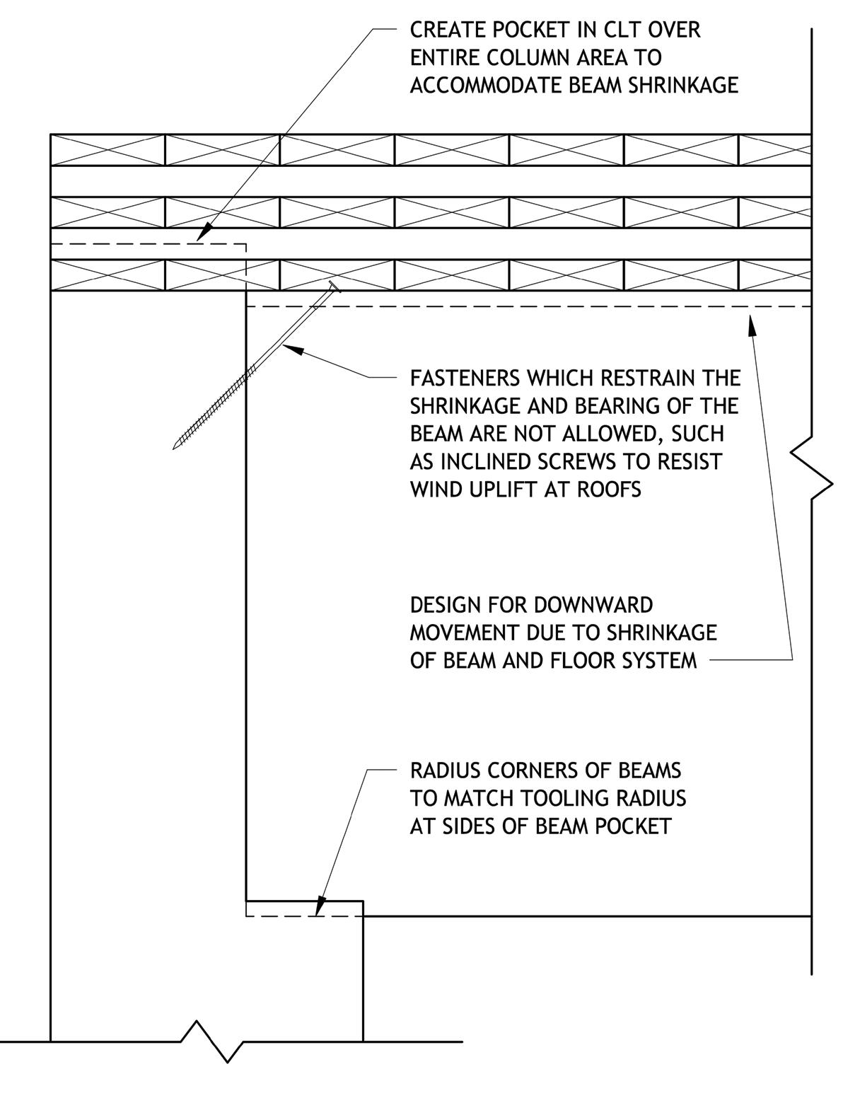
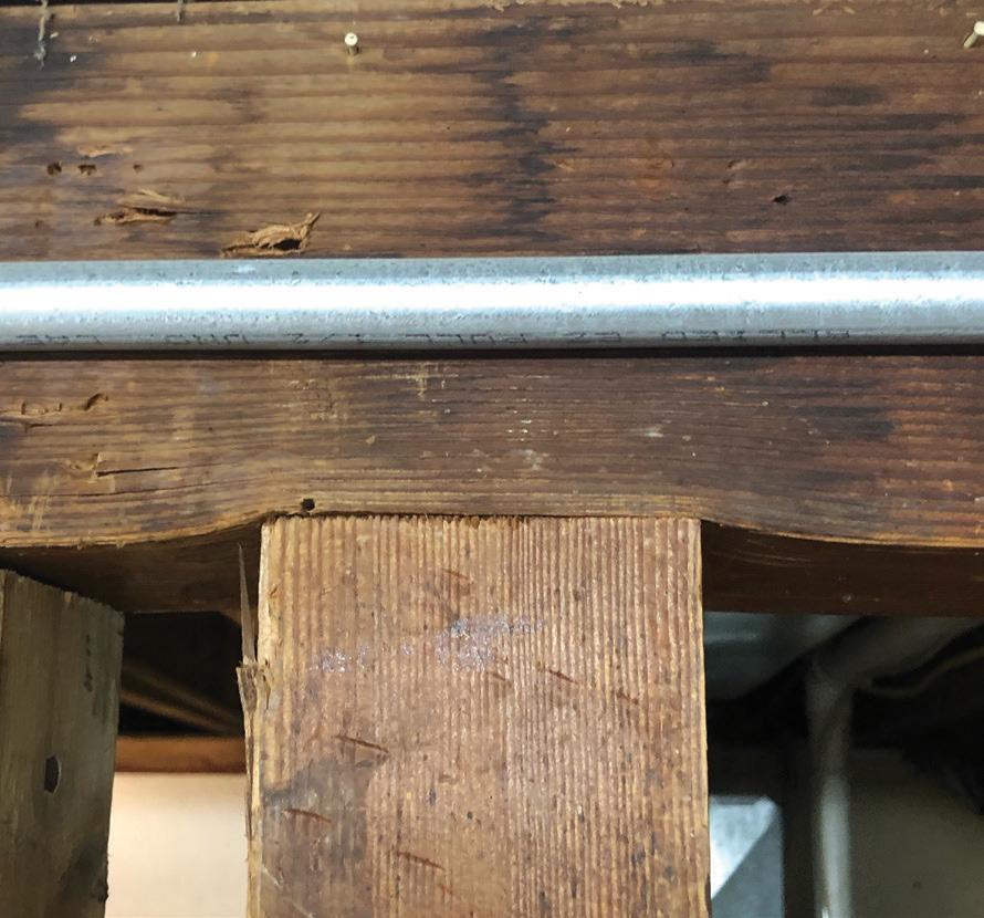
For a wood beam bearing on its bottom surface, the top of the beam will settle downward. The top of beam movement comes from two sources, shrinkage due to the moisture content change of the wood and compression of the wood fiber due to bearing (Figure 3). A rule of thumb is that wood beams may shrink 1% of depth for every 4% of moisture content change. Assuming that wet or “green” timber beams would not be used, specify timber beams with a maximum wood moisture content of 19% (MC19) at the time of manufacture. Glued laminated timber (glulam) beams are manufactured at a maximum moisture content of 12% (MC12). It is not uncommon for interior building conditions to create moisture content in wood as low as 5% in an arid environment. As an extreme example, a 36-inch-deep timber beam with 19% moisture content may shrink 1¼ inches, while a 36-inch-deep glulam beam with 12% moisture content may shrink 5/8 inch, based on 1% shrinkage for every 4% moisture content change. When evaluating the compression-perpendicular-to-grain strength and deformation of beams, designers should be aware that the ASTM test for this value involves a 2-inch square steel plate bearing on the wood top surface and full-bearing of the wood on the bottom surface, which is different than the wood-on-wood bearing condition where a beam is compressed from roughly equal size bearing on opposite faces (see Characterizing Perpendicular-to-grain Compression Behavior in Wood Construction by Craig Thomas Basta, Rakesh Gupta, Robert J. Leichti, and Arijit Sinha). For beams loaded on opposing faces, the potential for buckling perpendicular-to-grain is a design consideration for evaluation of strength in addition to bearing (see NDS Commentary). The combined shrinkage and bearing movement also needs to be addressed. In the bearing intersection described in this article, the mass timber floor and beam are detailed to move downward around the column without compromising any of the connections. At roof conditions where wind uplift is a concern, fully threaded 45-degree screws at the top of beams are not an option, as the beam bearing and shrinkage require the freedom of the beam to shrink and take the full bearing load at the base of the beam (Figure 4). This is especially important for fire resistance. The beam must have full bearing on the column to prevent the formation of any gaps that would allow char intrusion into the beam bearing area.
fire-resistance rating required of the members or assemblies. As provided in Section 2304.10.1 of the 2021 International Building Code (IBC), fire resistance for protected connections in Type IV-A, IV-B, and IV-C mass timber construction must be determined either: 1) through a standard ASTM E119 or UL 263 fire-resistance test in which the protected connection is part of the tested assembly, or 2) through engineering analysis demonstrating that specified temperature rise thresholds are not exceeded within the connection. Under the engineering analysis option, calculations must be performed Figure 3. Deformation at beam bearing. to show that the average temperature rise at the interface between the protection and the connection itself does not exceed 250 degrees Fahrenheit and the maximum temperature rise at any location on that interface does not exceed 325 degrees Fahrenheit. Both temperature thresholds coincide with conditions of acceptance specified in ASTM E119, pertaining to tests of protective membranes in fire-resistance-rated assemblies. It is important to note that these temperature limits represent temperature rises – or increases above ambient temperatures
Fire Design
Where the code requires structural members or assemblies to have a fire-resistance rating, structural connections between the members must be protected for a time not less than the
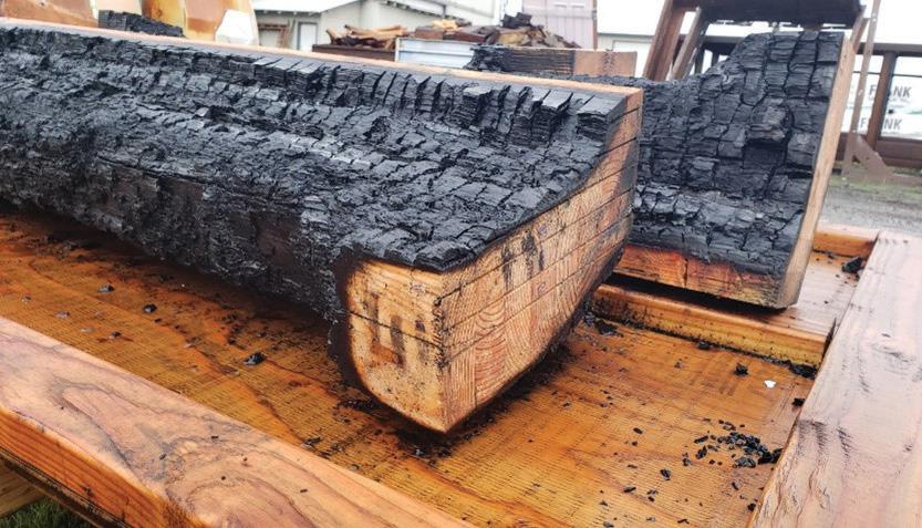
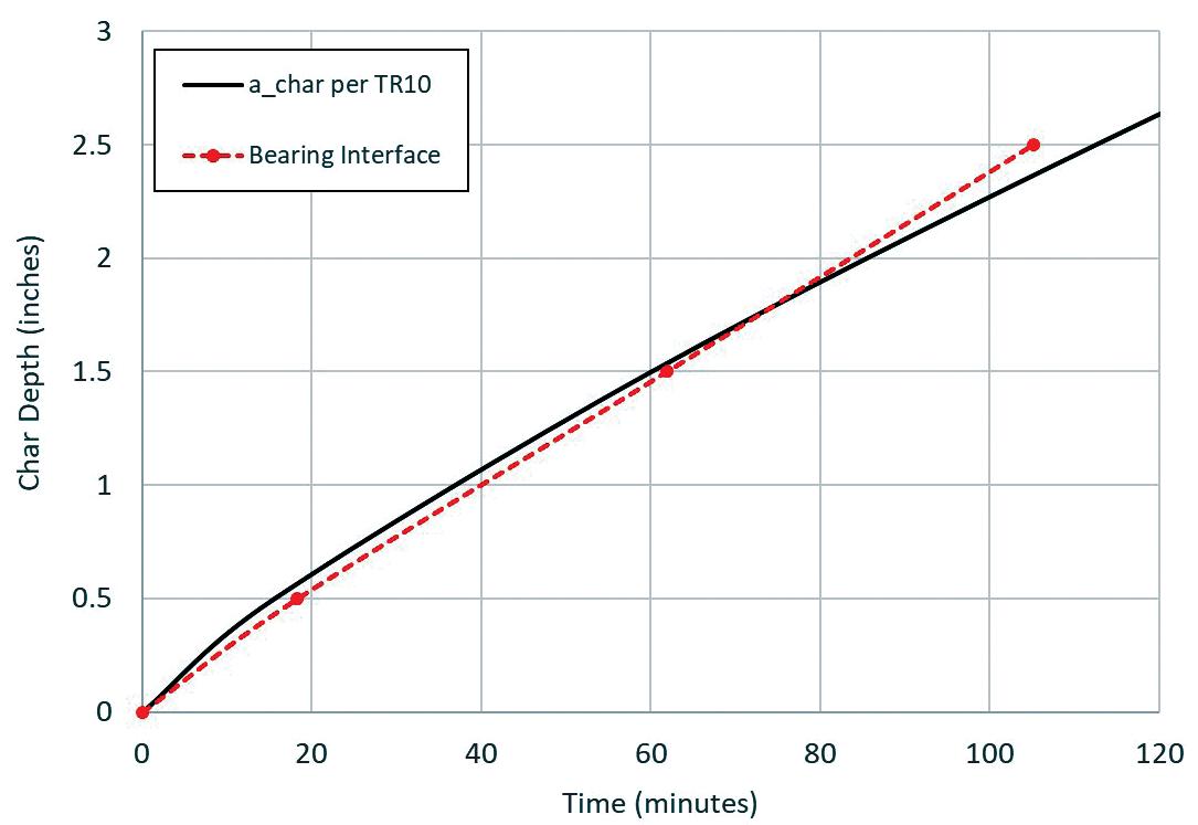
before fire exposure. It should also be noted that these temperature-rise criteria apply not only to the connection hardware but also to the fasteners and portions of wood members included in the structural design of the connection. The penetration of ignition into gaps formed by char contraction at unbonded wood member ends and edges must also be addressed. At any given exposure time, ignition is assumed to extend into these gaps at twice the char rate, resulting in a penetration that is twice the char depth, achar, of the wood (2achar versus achar). Protection must be detailed to ensure that no part of the connection, including all previously described components, is exposed to elevated temperatures due to char contraction. Connection protection may be provided by additional wood cover, Type X gypsum panels, other approved materials, or any combination of these materials. American Wood Council’s Technical Report 10 (TR 10) Calculating the Fire Resistance of Wood Members and Assemblies provides guidance to designers on how to estimate thermal separation times provided by wood and gypsum panels in order to demonstrate compliance with the temperature rise limits specified in the engineering analysis option of IBC Section 2304.10.1. For protection from additional wood cover or Type X gypsum panels to be effective, char contraction of the wood or contraction of the gypsum panel must also be addressed. TR 10 includes examples of how the design of this protection is achieved. Notably, recent testing has shown that this gap formation due to char contraction does not occur at bearing intersections between structural members where the members stay in contact due to loading (Figure 5). As shown in the graph (Figure 6), char depths measured at the bearing interface are generally equivalent to the char depths, achar, calculated in accordance with the NDS. As a result of this testing, the guidance regarding gap formation due to char contraction need not be applied to the design of bearing intersections that are even lightly loaded.
Figure 5. Uncharred bearing interface on the bottom of the beam after a 2-hour fire test. Elimination of char intrusion into the bearing seat is a significant advancement in the design and economy of this type of bearing connection. The reduced bearing area must still be accounted for using a depth of achar instead of 2achar, as shown in Figure 5. The American Wood Council’s newly released 2021 Fire Design Specification (FDS) for Wood Construction provides additional design guidance, including an adjustment factor of 1.67 for fire design of bearing perpendicularto-grain. The FDS is available on AWC’s website at www.awc.org. Conclusion A beam-to-column bearing connection, where minimal connection hardware is used, is an excellent option for designers and contractors. Understanding the shrinkage of the beams and how each floor will move down around the columns as the beams shrink is critical to detailing the connections of the building’s components to the structural frame. Understanding and allowing for rounded corners at CNC pockets and tenons will eliminate expensive additional labor to create square corners. It is important for the design team to have requirements for the submittal of a temporary bracing plan, as the diaphragm and beam-column type significantly affect stability during construction. Finally, proportioning the correct beam and column sizes to provide adequate bearing through the beam-column intersection (pre- and post-fire) and eliminating any obstructions or restraint that might prevent full bearing at the intersection starts at the earliest stage of a project. The connection type will dictate a specific layout of the column grid and will likely not be possible to implement on a project where the structural grid is set without the specific bearing connection in mind.■
D. Scott Nyseth is President of Stonewood Structural Engineers, Inc. in Portland, OR. (scott.nyseth@stonewoodstructural.com) Jason Smart is Director of Fire Engineering at the American Wood Council. (jsmart@awc.org)
