42 minute read
Historic Structures
Eden Train Wreck
Dry Creek Bridge Failure
By Frank Griggs, Jr., Dist. M.ASCE, D.Eng, P.E., P.L.S.
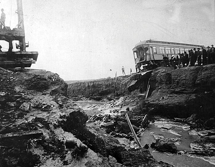
On the Denver & Rio Grande Railroad running from El Paso on the Rio Grande River through Pueblo to Denver, Colorado, the World’s Fair Flyer was traveling southerly towards Pueblo on the early evening of August 8, 1904, during a severe storm. At approximately 8 miles north of Pueblo, the line crossed an arroyo (generally dry creek bed). e arroyo was about 100 feet wide and 14 feet deep with steep banks.
A trestle had been built on wooden bents to cross the arroyo and on August 26, 1904, the Railway Age wrote,
“...a wooden structure, consisting of three spans, each 32 feet in length, and resting upon four bents. Numbering the bents from north to south, one and four consisted of posts standing on blocking and caps above supporting stringers, ties, and rails. Bents two and three consisted of seven piles driven 13 feet into the bottom of the channel and sawed off 6 feet below the surface. On top of these piles rested a sill 12 × 12 and fastened to them with two drift bolts, each ¾-inch in diameter and 36 inches long, driven through the sills into each of the piles. Resting on the sills of each bent and extending to the cap above were seven 12 × 12 posts, each fastened to the sills with two drift bolts ¾-inch in diameter and 22 inches long, driven through the sides of the posts obliquely into the sills. e outer posts on each side of the row of seven rested on the sides at an acute angle to aff ord the structure greater horizontal or side resistance. On top of the posts were placed caps 16 × 16, which were fastened to them by two drift bolts ¾-inch in diameter and 26 inches long, driven through the caps into the top of each post. e stringers were each 8 inches × 10 inches × 32 feet best Oregon timber. Four of these were bolted together and placed under each rail, making eight in all stretching from bent to bent. e ends of the stringers were joined by butt joints. Resting on the stringers were the ties and on these the rails. e outer one of each set of four stringers was fastened to the cap below by means of a ¾-inch bolt, with [a] nut on each end, which bolt passed through the cap, stringer, and tie above.”
A trestle with two bents in the waterway was standard practice for this kind of inexpensive bridge. e bridge had been in place for years with no signs of weakness. From the record, it does not appear that any signifi cant fl ooding had taken place during its lifetime. On August 9, 1904, the Colorado Springs Gazette wrote,
“ e engineer, Charles Hinman, had been given a thunderstorm caution and had slowed the train to 10-15 mph to watch for washaways. After the engine had crossed the creek, a large wave threw the cars over to the right, broke the coupling to the rear 2 Pullman and dining cars, and dragged the engine backwards into the river. e Pullman’s porter, Melville Sales of St. Louis, quickly pulled the emergency air brakes saving the remaining passengers. e front Pullman car was left hanging four feet over the edge of what remained of the bridge.”
It is thought that a county road bridge that had failed upstream was pushed downstream and may have impacted the Dry Creek Bridge, contributing to its collapse. However, it is unclear if the wave of water that hit the train was associated with the upstream bridge impacting the Dry Creek Bridge.
Dry Gulch with Pullman cars on the edge of bank and water subsided. A wall of water reportedly hit the front of the train as it was passing over the trestle and carried the engine, baggage car, smoking car, and chair car (a car with better, more comfortable seats) into the fl oodwaters. e two passenger cars were carried downstream by the fl oodwaters, drowning most of the passengers. e engine was submerged near the bridge; the chair car was found almost a mile from the bridge buried in sand, and the baggage and smoking cars were found more than 4 miles downriver. Of the hundred or more people in the two cars that plunged into the torrent, only three escaped along with the fi reman on the engine. e three did so through the fractured roof of the smoking car and swam to shore. e fi reman was thrown free of the locomotive. David Mayfi eld, the fi reman, later stated, “We did not expect anything at all. We were going along at a good speed all the time and never dreamed that anything was wrong. We thought that if there were any kind of a fl ood near Eden, the operator there would know, and he would fl ag us. We passed there but saw no signals of any kind and never felt any fear… I scarcely know how it happened, as I was dazed in the mud on the bank of the creek. It all happened so quickly – and, my God, it is so terrible. A little while before we reached the bridge that crosses Dry creek, I turned to Charley Hinman, the engineer, and said to him: ‘Charley, is there enough steam to carry us to Pueblo?’ Charley said, ‘No,’ and I began fi ring up. Just as I was putting the second shovelful of coal in, the engine gave a lurch upward. I lost my balance and was thrown from the train on the bank of the creek. I must have struck partly on my head, as I was dazed and did not know what happened for several minutes. When I came to, I saw the Pullman cars standing near me but could not see the engine or the rest of the train. I went up and down the stream When the fi rst crash came, we looking for my partner, Charley, the engineer. I didn’t notice whether water was running in were riding along as smoothly over the trestle as we approached the bridge as one could go…It was just as but, when I was thrown out, the water was much higher than the tracks.” though the train had struck One of the survivors later wrote, “When the fi rst crash came, we were riding along as a stone wall. smoothly as one could go…It was just as though the train had struck a stone wall. e lights went
out, the fixtures and everything fell down, and the passengers were thrown forward, and there were the most awful cries for help and the grinding of timbers. I saw the man next to me was down, and I helped him up, but just then, another crash came, and the train seemed to sink about five feet. I lost sight of everybody and couldn’t think of anything but to save myself. I remember well the sensations that I had at that time. I knew I was in terrible danger, and my first thought was that I must get out of the car. At the second crash, I was about up to my waist in water. All the time, the grinding and crushing of timbers was going on. In another crash, I was thrown about a third of the length of the car right up against the front door. I grabbed the top of the door, and the car went over in the water three times. My first instinct when the water went up over my head was to hold my breath. I think I was under water for a full minute. The car naturally righted, and when it came up, the water was just about my lips. I could breathe all right and saw the transom was just above me. With my right hand, I smashed out the glass, hoping that I could get out in that way. At that moment, another crash came, and I was struck in the forehead by some floating object and dazed, but managed to keep my head above the water and after a terrific struggle reached the shore.” When all the bodies were recovered, about 100 persons had drowned in the arroyo, which a few hours later was dry once again. A Pueblo newspaper reported, “Deep gloom has settled down upon the city today following the railroad horror, which snuffed out a hundred or more lives yesterday. Many business houses are closed out of respect to the dead, and more than forty private homes are darkened and in mourning.” On August 19, the Railway Age quoted J. A. Edson, the Manager of the Denver & Rio Grande, who said, “…the company was in no way responsible for the wreck at Eden, Colo., on the night of August 7. ‘It was one of those unavoidable accidents which are liable to occur on any railroad when a flood of the character that washed out our bridge occurs.’ said Mr. Edson. He further stated, says the dispatch, that the bridge was subjected to regular inspections of the company’s bridge superintendent and was as safe as any other on the Denver & Rio Grande, or, in fact, on any road, and that no bridge could have withstood the torrent that destroyed this one. The under bents of the bridge, he said, were undoubtedly knocked asunder by the washed-out county bridge, thereby leaving no support.” As was typical in these crashes, a coroner’s jury was convened. They met for 11 days and submitted their 11 findings on August 21, 1904. They decided, (1) The water not being over the tracks at the bridge, but several inches below the banks, neither the engineer nor the fireman could possibly see it. The track being in line and level, nothing wrong with the bridge could possibly be seen by them. When the first impact took place, the Pullman passengers were not thrown forward out of their seats, besides positive testimony on the point, shows the train was running slow according to order, and the crew is therefore blameless. (2) If the county bridge was a factor in the destruction of bridge No. 110-B, the railroad company was to blame for not constructing a bridge that would avoid or withstand its impact as it knew the county bridge was there. (3) Had a bridge of one span on abutments with no obstructions in the channel of the stream to obstruct the flow of water or passage of debris, or stone arches of 110 feet, it would have in all human probability withstood the force of both the volume of water and the impact of the county bridge (if the latter took place) and the catastrophe would not have occurred. (4) Bridge No. 110-B was not of the best class of bridges used by railroads throughout the country. (5) Inspection close up to the time of the wreck showed bridge No. 110-B to be in its usual condition. Its weakness consisted, not in its condition, but in the cheap, inferior class to which it belonged. (6) Had the heavy downpour in the vicinity of Eden at 7:13 pm been reported to the train dispatcher at Pueblo, he might have delivered additional caution orders to No. 11 at Buttes before she left at 7:30, and the disaster might have been averted. (7) The conductor of No. 7 reported water over the track two miles south of Eden on arrival at Pueblo at 7:55 pm and a downpour at Eden and had a night or operator been stationed at Wigwam, eleven miles from bridge No 110-B, or at Pinion, five miles from it, train No. 11 could have been warned, and the disaster averted. (8) Had a regular system of track-walkers and flagmen, independent of the section men, been maintained by the company over the track in question, especially in the afternoons, evenings, and nights during the rainy season, No. 11 could have been flagged, and the disaster averted. (9) Had bridge No. 110-B been under charge of the section gang at Eden, one mile away, instead of the one at Pinon, five miles away, No. 11 would have been flagged, and the disaster averted. (10) Bridge No. 110- B should have been so constructed as to withstand all the water the arroyo could accommodate. On the night in question, the arroyo accommodated all the water that came down, but the bridge collapsed. (11) If bridge No. 110-B had been a one-span metal bridge with stone abutments, the probability of damage by the county bridge would have been much lessened. Therefore, the jury finds that the appalling loss of life and property at bridge No. 110-B on August 7, 1904, was due to the negligence of the Denver & Rio Grande Railroad Company as set forth in the foregoing statement of findings and conclusions. Newspaper headlines following the findings included,
RAILROAD IS RESPONSIBLE FOR THE EDEN DISASTER Jury Brings in Set of Vigorous Findings, That the Bridge was not the right class, That there Was No Regular System of Trackwalkers, That D. R. G. was Negligent.
Lawsuits were filed, and the total loss to the Company amounted to almost $250,000 for the lives lost, with some bodies never found. There is no doubt of the seriousness of this disaster. Still, the Coroner’s Jury findings #3 and #11 that a single span bridge would have prevented the failure is not provable, as many single span wood and iron bridges had been washed out during major storms around the country. Finding #4 is also questionable, as the bridge appeared appropriate for the loads placed on it. It could be argued that it was an Act of God, and the magnitude of the flood and the washing out of a bridge upstream could not have been foreseen. As to #5, it was not a cheap, inferior class of bridge but one that was appropriate for the site on which it was built. In summary, the sequence of events leading to the failure could not have been planned. In a failed bridge upstream, riding on a flood of unheard-of proportions hitting the bridge at the moment a train was passing over, it was not, and probably could not, have been designed. It should also be pointed out that Coroner’s Juries did not normally have trained engineers on them but were local laypersons who were, after investigating the failure and talking with survivors and experts, called upon to make an engineering judgment. The other judgments they made were very reasonable given the perfection of hindsight.■
Dr. Frank Griggs, Jr. specializes in the restoration of historic bridges, having restored many 19 th Century cast and wrought iron bridges. He is now an Independent Consulting Engineer. (fgriggsjr@twc.com)
In-Situ Evaluation of Old Pan-Girder Bridges
By Nur Yazdani, Ph.D., P.E., F. ASCE, F.SEI, F.ACI, and Eyosias Beneberu, Ph.D., P.E.
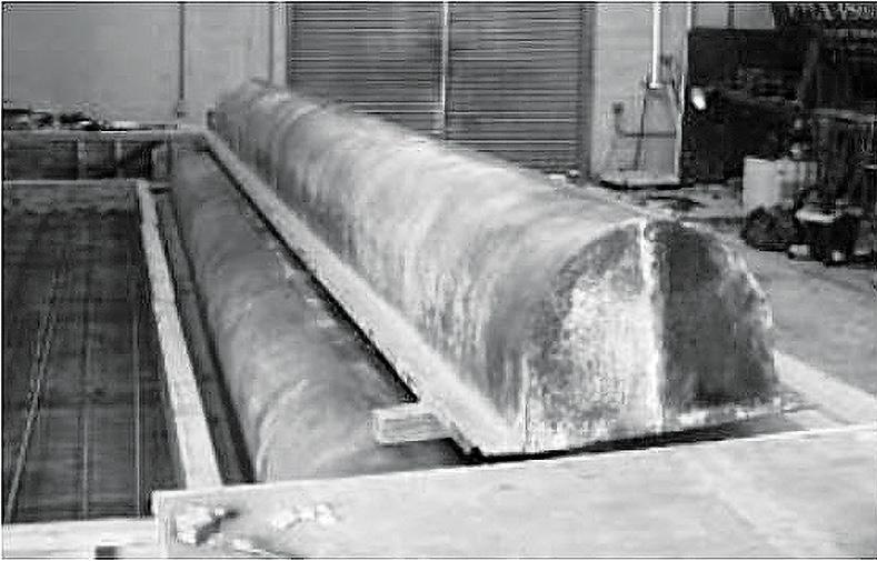
Figure 1. Metal pan form.
The Texas Department of Transportation (TxDOT) employs various concrete bridge superstructure options depending on span length, traffi c, and future crossing requirements. Among these, pan-girders were a popular choice in the 1950s and 1960s as a viable alternative for short-span bridges due to their speed of construction, low labor requirements, and cost-eff ectiveness. e name “pan-girder” came from the pan-shaped formwork that was used in construction. e formwork consisted of an upper semicircular cross-section with straight ends on the bottom of each side (Figure 1). Pan-girder bridges were cast using self-supporting metal forms that spanned between bent caps. Multiple pans could
be placed next to each other to form a concrete web. ey were connected with bolts that passed through holes on the sides of the forms (Breña, 2001). e pan forms supported the dead weight of the reinforcement and wet concrete, thus eliminating the need for shoring and falsework. ere are about 4,000 pan-girder bridges still in service in Texas, mainly designed for AASHTO live load designations of H10, H15, H20, HS15, and HS20 trucks. Even though they were originally designed for lesser loads, many pan-girder standards rated out at acceptable levels for HL-93 loading. e standards designed using the lightest AASHTO design loads (H-10 and some H-15) usually did not have an acceptable load rating at the HL-93 level. e decline in the use of pan girders occurred prior to the introduction of the HL-93 design load. Over time, pan-girder construction became labor-intensive, with much time dedicated to tying reinforcing and placing concrete in the pan forms. As the precast industry expanded in Texas, the cast-in-place bridge superstructure types fell out of favor due to economic reasons. With the advent of the heavier current AASHTO HL-93 design load (AASHTO 2011), the use of pan-girder bridges declined even more. Due to a large number of these types of bridges, pan-girder bridges have been investigated for overall safety assessment and rehabilitation using external composite laminates. Because the bridge pans were not perfectly straight, fresh concrete could fl ow through gaps between adjacent forms during casting, leaving an irregular surface on the bridge webs. While this irregularity had no impact on the bridge performance, it can infl uence the placement of composites used to strengthen the bridges. is Figure 2. EB US 80 Bridge over the frontage road top view (map data: ©2018 Google). means composites could not be placed in the middle of the web without fi rst doing some signifi cant surface preparation, increasing labor cost and construction time (Breña, 2001). For the study discussed here, an in-situ evaluation was conducted of the East Bound (EB) US 80 pan-girder bridge (Figure 2) over a frontage road in Forney, Texas, through visual inspection and condition assessment. TxDOT recommended the inspections to catalog the current Figure 3. Detail along the transverse section. bridge condition in order to
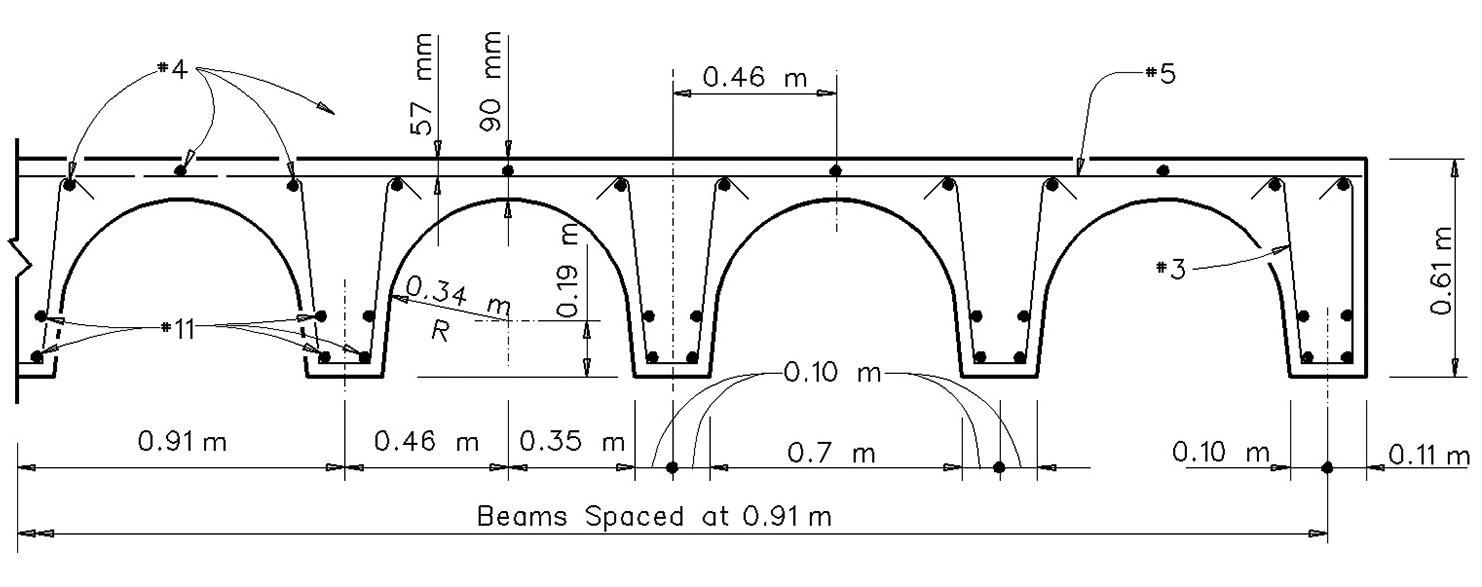
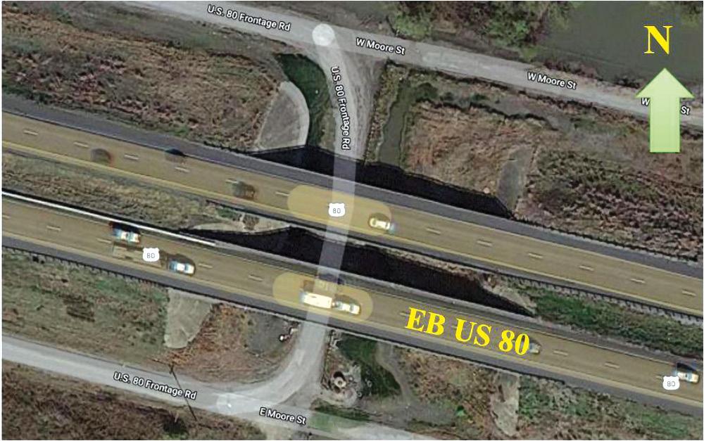
undertake future load rating and any strengthening that could be necessary. It is a 10 span and 252-foot-long bridge constructed in 1955. At each bent, there exist three separate bent caps. e fi rst, second, and third bent caps support one, 10, and 3 beams, respectively. e bridge was widened in 1978 when one beam (Beam 1) was added to the north and three beams (Beams 12, 13, and 14) were added to the south of the existing bridge. Figure 3 shows the typical detail along the transverse section of the bridge. A detailed visual inspection plan was prepared, and the structural elements were evaluated for visible signs of distress, damage, and deterioration. Various types and levels of damage that could jeopardize the overall health and serviceability of the bridge’s structural elements were located and cataloged. Deteriorations included, but were not limited to, hairline cracks, concrete crushing and spalling, and water damage. Observed damages are summarized in the Table. Beam numbers are progressive from north to south. Identical beams in various spans showed similar levels and types of damage, and these repetitive damaged numbers of beams are shown in parenthesis after the corresponding beam numbers. For example, 3(2) indicates that beam number three in two spans showed an identical type of damage. In addition, it is apparent that most beams sustained some form of water damage at mid-span, as shown in Figure 4 (page 44).
Table of EB US 80 Bridge condition summary. Damage Beam Numbers
Exposed aggregate 6
Chipped concrete 3 (2), 11 (4), 6, 7, 10
Concrete crushing at support 2, 7, 11 (2)
Delamination 11
Hairline cracks 1, 2 (2), 3, 4 (2), 5 (2), 6 (2) 7 (3), 9 (3) 8, 10 (2), 11 (2), 13 (2)
Honeycombing 10
Longitudinal crack along crest 6, 7, 8, 9 (2), 10, 11, 13, 14
Exposed rebar 6, 7, 11 (2)
Concrete scaling 2, 3, 7 (4), 8, 9, 10 (3), 11 (4)
Concrete spalling 2, 7, 11 (2)
Water damage 1 (8), 2 (9), 3 (10), 4 (10), 5 (10), 6 (10), 7 (10), 8 (10), 9 (10) e presence of form lowering holes at the crest of the pan girders at quarter-span and mid-span of the girders could be the reason for water damage, as the water seeped through the holes. Effl orescence was visible in the form of white and gray residue, which occurs when the calcium salts from concrete react with water and air to form insoluble calcium carbonate. is phenomenon is harmful to concrete as salt can increase concrete permeability and induce corrosion of steel rebars. Corrosion propagated from the drainage areas in most of the girders, and a few beams had exposed rebars. Rebars were exposed and corroded in some of the beams around the form lowering holes. Such corrosion could occur due to the water
ADVERTISEMENT–For Advertiser Information, visit STRUCTUREmag.org
DuraFuse Frames systems are highly ductile systems are highly ductile steel moment frames with one-of-a-kind resilience, exceptional performance, and improved economy. Numerous connection configurations provide the ideal solution for all building types both new and retrofit. Our design team is dedicated to being a seamless extension of your team to provide a resilient steel moment-frame solution. DuraFuse Frames benefits include:

The ONLY resilient, repairable connectionsONLY resilient, repairable connections Optimized design results in reduction of overall frame weight Significant reduction (up to 70%) in seismic lateral beam bracing requirements Fewer parts, simpler fit-up and lower weight compared to other proprietary moment connections
overall frame weight other proprietary moment connections
www.durafuseframes.com




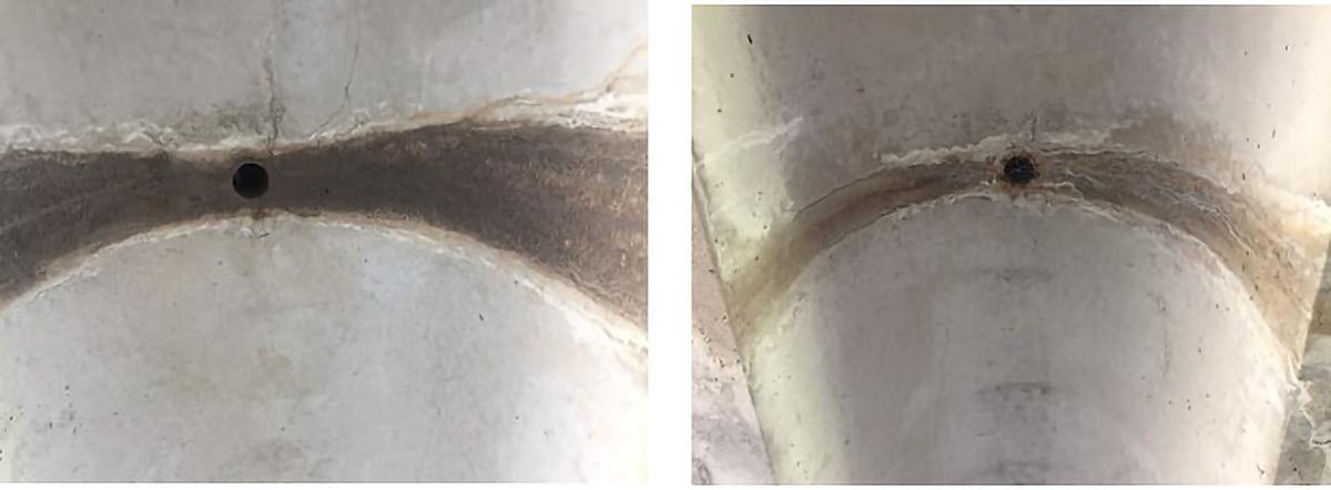
Figure 4. Water damage at mid-span.
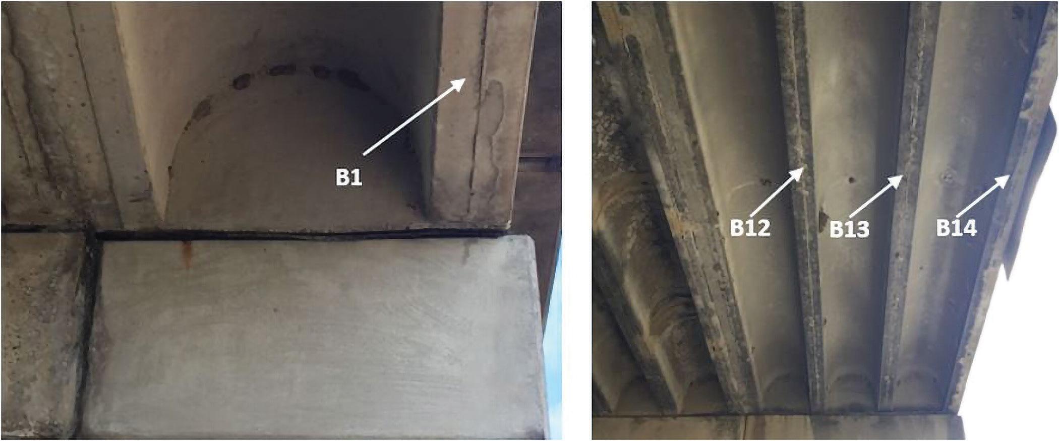
Figure 5. Condition in newer beams.
seepage from the holes, which caused concrete scaling and spalling. However, no corrosion was observed in the primary longitudinal reinforcement, located at the bottom of the stem. If present, corrosion in the rebar could potentially affect the load-carrying capacity of the beams. It may be noted that beams 1, 12, 13, and 14 displayed little or no water damage. These beams were added in 1978 during the bridge expansion, while the other beams were in service for about 23 additional years. The four newer beams were in much better shape and did not show any extensive visible deterioration and/or water damage (Figure 5). The new bent caps used for the widening were connected to the existing bent caps with dowel bars for continuity. Beam 11 was the most severely damaged in all spans, with practically all the deterioration mentioned in the Table. Water damage was visible in this beam at every quarter-span location in all spans. Samples of deterioration are shown in Figure 6. This could be caused by the fact that Beam 11 was on the exterior side before the bridge widening; after widening, it became an interior beam that increased the load it carried and aided in the damage process. The following recommendations, which can be applied to this and other pan-girder bridges, were made based on findings of the field inspection: 1) A PVC pipe can be glued on the form lowering holes extending beyond the concrete surface of the arch. This will prevent water seepage through the holes and minimize water damage, spalling, and scaling of concrete. 2) Pan-girder bridges were usually designed for a load lighter than the current AASHTO HL-93 live load requirement. Therefore, it is recommended that appropriate load testing, load rating, and analyses be undertaken for such bridges, especially older ones with significant deterioration, to verify the loadcarrying capacity and adequate structural safety. 3) Appropriate retrofitting and repair techniques may be used to upgrade deficient pan-girder bridges with extensive deterioration. For example, experience has shown that externally bonded Carbon Fiber Reinforced Polymer (CFRP) laminate is a viable method for strengthening concrete bridges in general (Mohanamurthy and Yazdani, 2015; Pallempati et al., 2016) and also for under-capacity pan-girder bridges.
Thus, such rehabilitation methods may be suitable to upgrade deficient pan-girder bridges. In conclusion, the study conducted herein showcased common deteriorations and distresses in a typical pan-girder bridge. The results indicate it is essential to conduct a detailed visual inspection on similar bridges to understand their current condition and undertake strengthening if they are deemed to be unsafe.■
Full references are included in the online PDF version of the article at STRUCTUREmag.org.
Nur Yazdani is a Professor in the Department of Civil Engineering at the University of Texas at Arlington. (yazdani@uta.edu) Eyosias Beneberu is a Structural Engineer with Bridgefarmer & Associates in Dallas, Texas. (eyosias.beneberu@mavs.uta.edu)
a) b) c)

suitable to preserve. It had been repaired in the 1900s with brick rings, and a keystone was inscribed with that date. Five alternative project approaches were presented, ranging from a minimal renovation to a complete replacement with a pre-cast concrete arch. Ultimately, the bridge owners opted for a major renovation with reinforced concrete to strengthen the historic arch. e phase that followed included both preliminary and fi nal design of the recommended alternative and preparation of right-of-way plans.
Preserving the Stone Arch
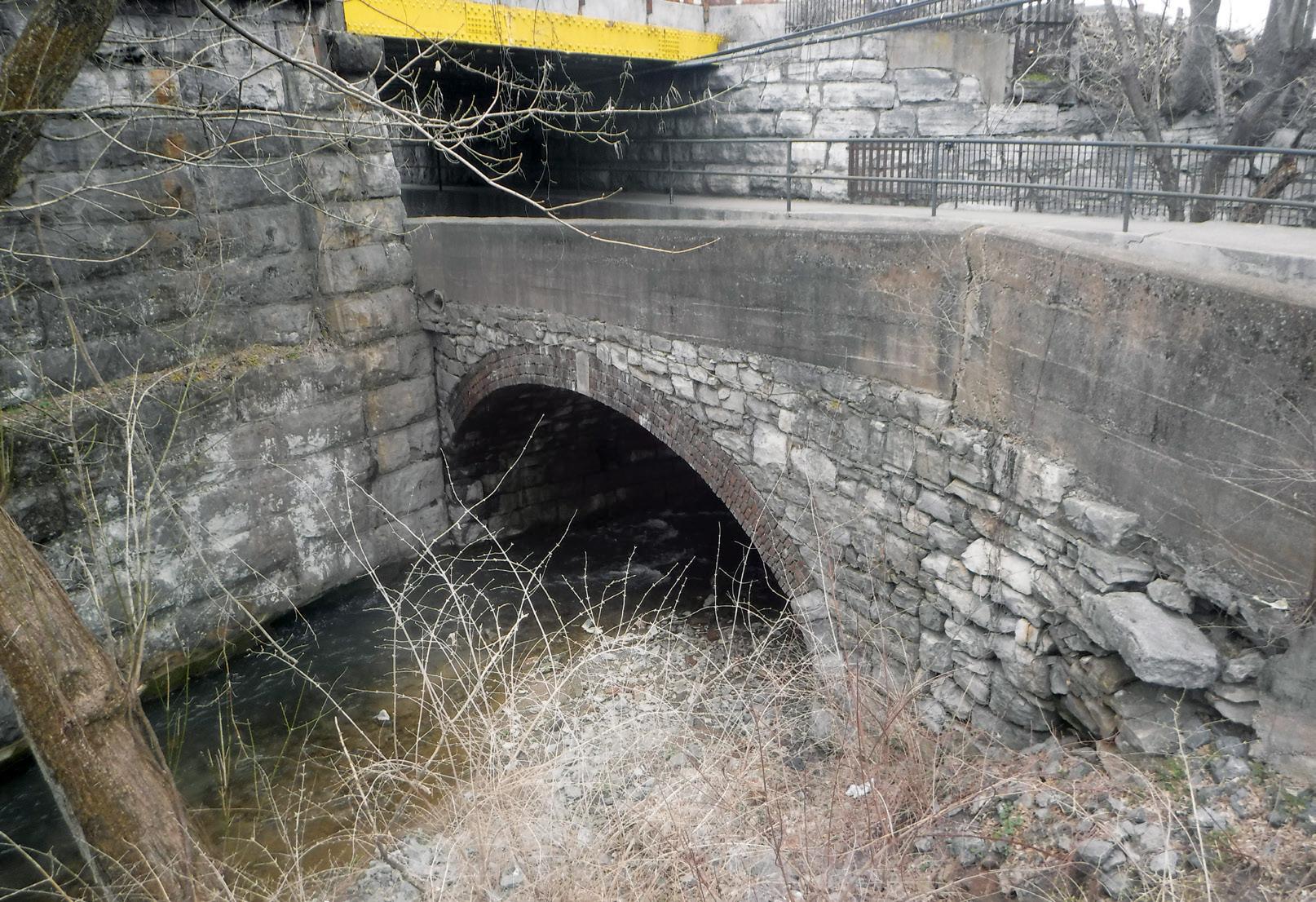
The cracked and deteriorating historic bridge before restoration.
The East Burke Street Bridge is an important vehicular and pedestrian connection between downtown Martinsburg, West Virginia, and neighboring residential areas. Equally important as the bridge’s function is its rich history dating back to the Civil War. Believed to be originally constructed in 1861, the bridge survived a Confederate attack that destroyed an adjacent bridge and other buildings.
Structural defi ciencies, including unstable wingwalls, loss of mortar, sidewalk settlement, and missing, cracking, or loose stones were identifi ed in 2010. As a result, the City of Martinsburg and the West Virginia Department of Transportation (WVDOT) sought a solution that would increase load capacity while retaining the historic aspects of the structure. is required a phased and tailored approach that allowed the team to work around the delicate condition of the historic parts of the bridge. e City and WVDOT worked with design engineers Burgess & Niple using a multi-phased approach. e fi rst phase included survey, mapping, geotechnical borings, condition inspection, hydraulic analysis, and preparation of a bridge renovation study. e initial study included document research to identify the bridge’s historic signifi cance and indicated that the structure was most likely built in the 1860s. is information was used to compare alternatives for renovating and replacing the structure. e inspection determined that the arch barrel of the bridge was the only portion of the structure that was
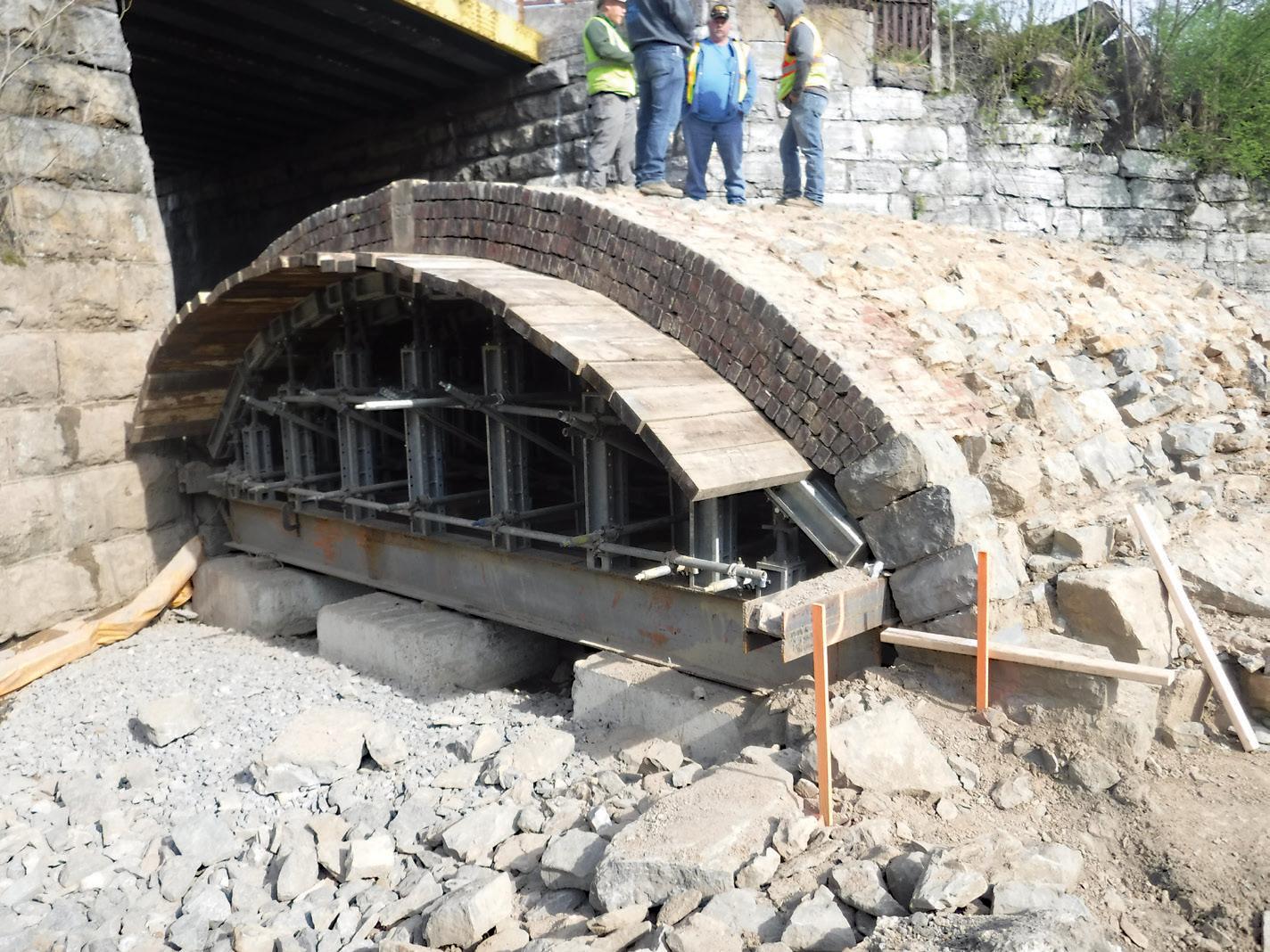
e project team’s goal was to maintain the existing stone arch while providing an alternate structural system to carry traffi c loads. A rigid frame was constructed in direct contact above the stone arch to accomplish this. e rigid H S frame system consists of a concrete rib that follows the existing arch line and a concrete slab that functions as the roadway surface for A R the bridge. e new frame was constructed by installing falsework under the existing arch barrel, removing the wearing surface and earth fi ll, and then constructing the new frame on M A top of the existing arch. e contractor’s falsework was a series of steel W16 beams, couplers, and posts with diagonal bracing, which supported 3-inchBY MATT LEWELLYN, P.E. thick timber planking placed just below the stonework. After mats of epoxy coated rebar were tied into place, the arch rib was formed and poured directly on top of the existing stone barrel. e concrete rib was bonded to the stone using an epoxy bonding agent, applied before the pour. Next, gravel fi ll was installed to fi ll the voids within the concrete frame, and the concrete slab was constructed on top A new reinforced concrete arch was designed and placed over the top of the existing arch to provide full live load capacity.
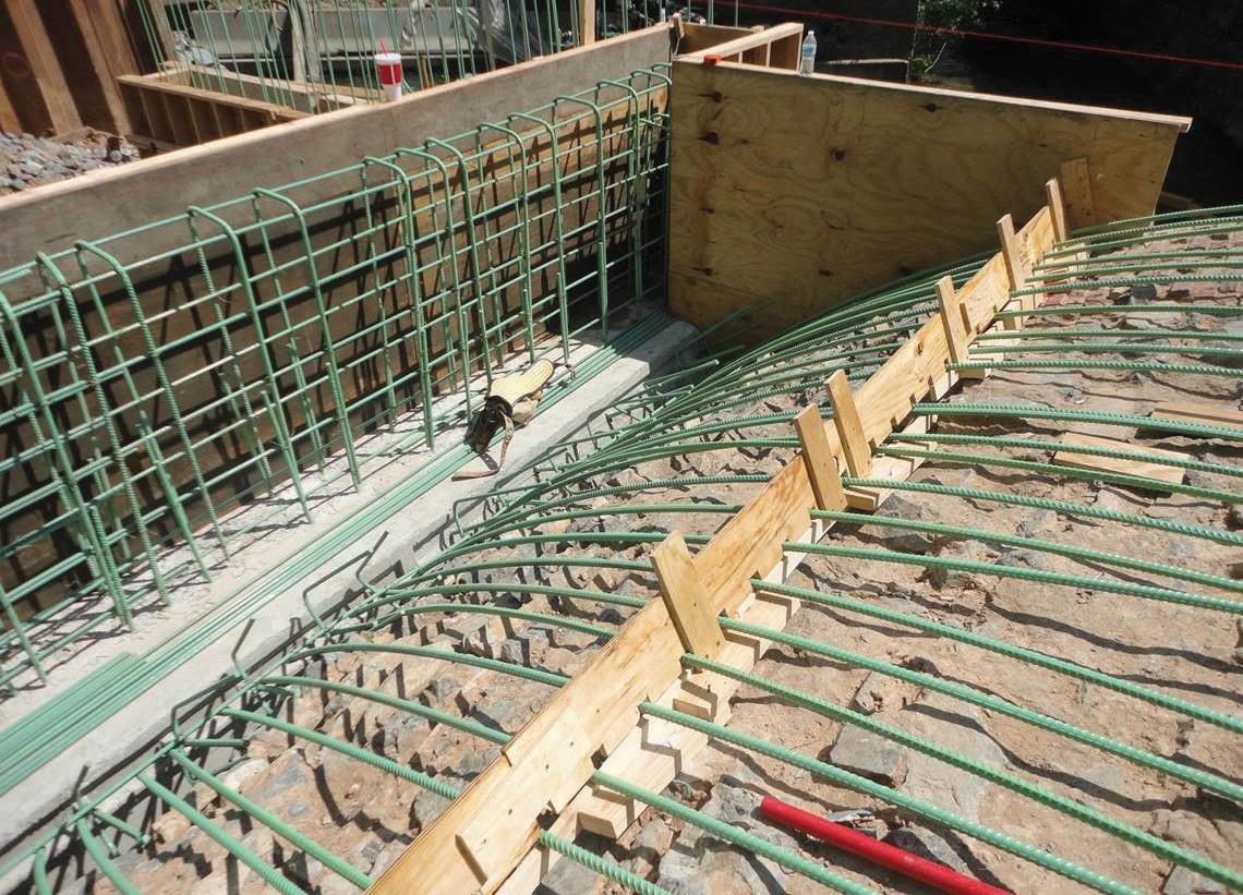
of the fill, with the midspan portion constructed integrally with the arch rib. Like a new bridge, this hidden structural system provided durability and increased load capacity.
The MIDAS Touch
The rigid frame support system was analyzed using a MIDAS finite element model that considered construction staging and the effects of soil-structure interaction on the behavior of the frame. The keyed construction joints at the base of the concrete rib were considered classical hinges for the analysis model and were treated as pin supports. The rib and slab elements intersected at a reinforced “knuckle” region and were modeled as moment-continuous. The ends of the slab elements are supported by bearing walls at the abutments and were modeled as pin supports. The compressive capacity of the existing stone arch was neglected in the analysis, and the existing stonework was included only as dead load. Forces extracted from the model were used to perform design computations for the frame. The frame was designed for the interaction of axial and bending loads, with particular attention given to the reinforcing details in the knuckle regions to control stress concentrations. Support reactions from the model were used to design the micropile foundations. Load combinations producing maximum vertical load, thrust, and overturning effects were identified to determine the controlling design condition.
Use of Micropiles
Sensitive ground conditions, steeply sloped bedrock, and adjacent structures made micropiles a good option for the East Burke Street Bridge. A total of 41 micropiles support the forward abutment and parallel wingwalls. Load testing was performed to confirm that the maximum factored axial load of 154,000 pounds per pile would be adequately developed. The rear abutment is founded on a spread footing placed directly on the bedrock. Several of the 7⅝-inch-diameter micropiles were installed at an angle to accommodate both axial and lateral loads. The outer casing pipe and drill rods advance through overburdened soils to rock and continue to pile tip elevation. Drill rods and casing were added in 5- or 10-foot lengths. Drill cuttings travel up the inside of the casing using air and water and are discharged through a swivel on the drill head. The piles penetrate 10 feet into bedrock to provide the bond zone for the grout, which is placed through a 1-inch high-density polyethylene (HDPE) tremie pipe to the bottom of the hole. A single number 11 reinforcing all-thread bar (Grade 75) was placed in the middle of the micropile. The micropiles provided a strong foundation without using a more traditional driven steel H-pile that could have shaken the ground and caused damage to the stone arch barrel, which would be temporarily supported but still vulnerable to heavy vibration.
Technology Helps Preserve History
A high-definition survey scan provided a detailed point cloud of existing geometry for stone mapping. The scan was used to
East Burke Street Bridge MIDAS model.
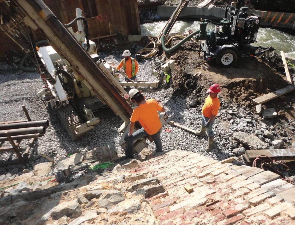
Burgess & Niple designed the bridge with micropiles instead of hammer-driven piles to reduce vibrations adjacent to the existing stone masonry.
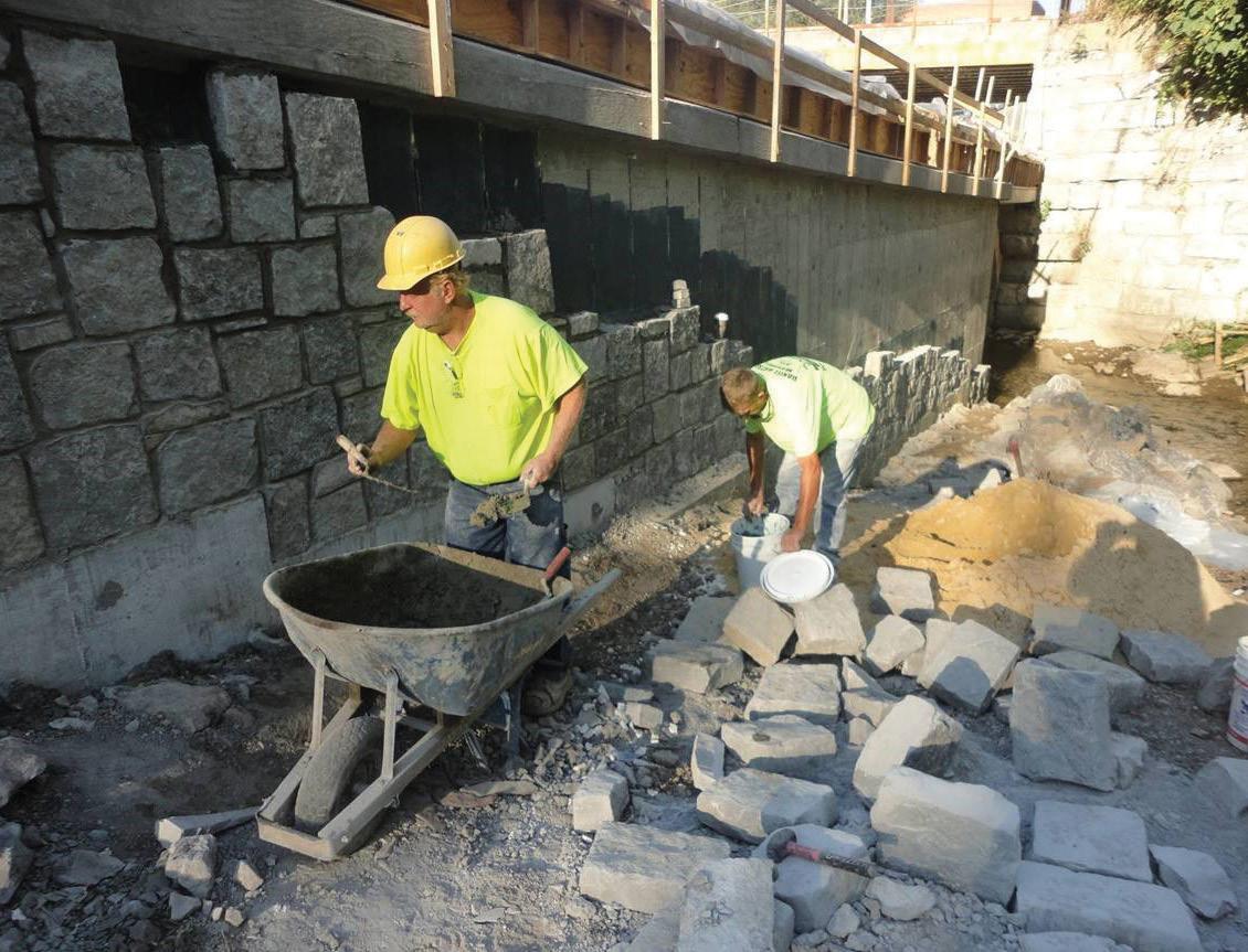
The East Burke Street Bridge arch as it is unearthed.
assess the condition of the material and arch structure and helped preserve as much of the viable stonework as possible. As a result, the arch barrel was cleaned and repaired with a lime mortar mix, cracked stones were repaired, and missing or damaged stones and bricks were replaced. In addition, the new concrete spandrel walls, wingwalls, and barriers were faced with stone masonry, some of which were reused from the existing walls. Thus, using the scan helped sustain as much of the bridge’s history and character as possible. As the arch was unearthed, additional issues were discovered. Predictions made about the width of the existing foundation stones were not accurate. The stones were much larger and conflicted with the placement of the concrete foundation as designed. Trimming the stones was discussed, but the team decided not to risk disturbing the arch. Instead, Burgess and Niple adjusted the structural model to account for thrust of the larger span, and revised plans were issued to keep the project moving. This required three additional micropiles and additional battering of the piles.
History Preserved. Safety Restored
Through this rehabilitation project, the City of Martinsburg preserved parts of the bridge’s history while increasing safety and load capacity for travelers. This intricate rehabilitation was achieved with several innovative strategies, such as the use of micropiles and high-definition survey software to address design and construction complexities. In addition to the project team’s approach to obstacles, including the proximity of the active railroad and weather-related disruptions, these strategies made this award-winning project a success.■
Matt Lewellyn is a Project Manager in the Burgess & Niple Parkersburg, West Virginia office. He is a national leader in bridge inspection, load rating, preservation, and rehabilitation. (matt.lewellyn@burgessniple.com)
Project Challenges
Project Team
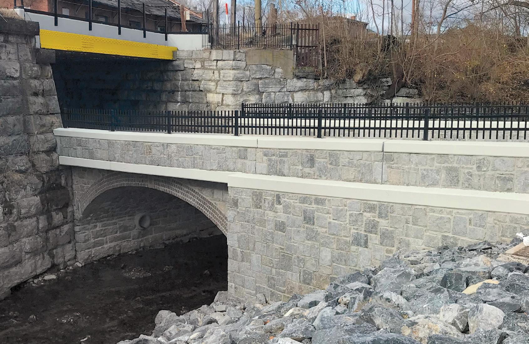
Owner: City of Martinsburg, West Virginia The project team faced several challenges during the construction Project Administration: West Virginia Department phase of the project. One of the most significant was the location of Transportation of the bridge approach under a railroad. To allow the railroad to Design Engineer: Burgess and Niple, Inc. remain operational during the rehabilitation, the contractor had Geotechnical Engineer: Terracon, Inc. to provide pre-construction photographs and video of the over- General Contractor: Orders Construction Co., Inc. passing railroad abutments and walls. During excavations, survey Micropile Contractor: Coastal Drilling East, LLC monitoring was performed to confirm there was no movement of the railroad structure. In addition, inspections were conducted following the excavation of each stone masonry course to ensure there was no distress caused to the railroad. If issues were observed, a corrective action plan was in place with materials and equipment on hand to immediately restore stability to the railroad. In the end, the action plan was not needed, which confirmed the assumption that the railroad bridge was structurally independent of the arch and supported directly on bedrock. Another challenge was the amount of rain that fell during construction, causing the Tuscarora Creek that passes under the bridge to rise, resulting in delays. High water resulting from above-average rainfall totals conflicted with the placement of the temporary support structure. To resolve this, the construction team rerouted a portion of the flow around the structure’s footprint by excavating an alternate relief channel in the east approach. The East Burke Street Bridge following the renovation.
Part 2: Adaptive Reuse and Structural Investigations
By D. Matthew Stuart, P.E., S.E., P.Eng, F.ASCE, F.SEI, A.NAFE, SECB
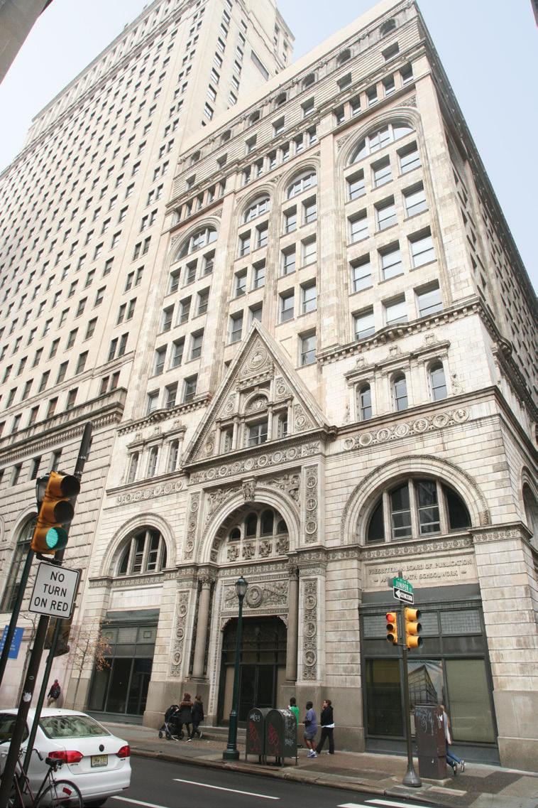
This four-part series discusses the adaptive reuse of the Witherspoon Building in Philadelphia, PA (Part 1, STRUCTURE , September 2021). Part 2 includes a discussion of the ongoing adaptations during construction and the structural investigations conducted to better understand the existing structure. Numbered photos are provided in the print version of the articles; lettered photos are provided only within the online versions of the articles.
Adaptive Reuse
This adaptive reuse project primarily involved the conversion of an office building to residential units. The Architect of Record for the project was Deidre DeAscanis, AIA, with JKRP Architects, Philadelphia, PA. Initially, the difference between the minimum required live load capacity for the upper floors of Philadelphia office buildings in the early 20th century (60 psf) as documented in the 14th Edition of the Architects’ and Builders’ Handbook by Frank E. Kidder (Figure 6) and the current-day live load required for residential areas (40 psf) were utilized to allow for a 20 psf reserve load-carrying capacity at the upper floor levels. Fifteen psf of the reserve loadcarrying capacity was dedicated to partition dead loads required by the current governing building code. The remaining 5 psf was dedicated for miscellaneous loads such as ceilings, mechanical, electrical, and plumbing dead loads. However, based on the results of an investigation of the 5th and 11th-floor framing, it was determined that the actual capacity of the typical floor beam framing was 100 psf, which provided even more reserve load-carrying capacity than that indicated by the comparison of the building codes. In addition, earlier references similar to the Architects’ and Builders’ Handbook from the late 19th century indicate that the minimum live load for all floors of an office building in Philadelphia was 100 psf. The minimum required live load capacity for the first floor of Classes of buildings Philadelphia office buildings in the late 19th and early 20th centuries (100 psf), as documented in the Architects’ and Builders’ Handbook, was used for the evaluation of the adaptive reuse of the first floor, which included retail space, the main entrance lobby, and residential areas. At the residential areas of the first floor, new loft areas were made accessible from the first-floor residential spaces below. At these same areas, the combined loading of two occupied levels of 80 psf live load and 40 psf dead load (not including the dead load of the new loft floor framing and access stairs), for a total of 120 psf, exceeded the assumed existing 100 psf capacity of the first floor. This same assumed 100 psf load-carrying capacity established by the code research was also subsequently confirmed via the existing 1st-floor framing investigation.
Minimum live loads per square foot of floor New York 1927
Philadelphia 1929 Boston 1926 Chicago 1928 Denver 1927 San Francisco 1928 Dept. of Commerce
Dwellings.............. 40 40 50 40 60 and 40 40 40
Hotels, Tenements, Lodging-houses, Hospitals 40 40 50 40 90 and 70 40 40
Office-buildings:
First floor...........
Other floors........ 100 60 100 60 125 60 125 40 120 70 125 40
100 50 School class-rooms 75 50 50 75 75 75 50 Buildings or rooms for public assembly:
With fixed seats......
Without fixed seats.
Aisles and corridors. 100 100 100 60 100 100 100 100 100 75 125 125 90 120 120 75 125 125 50 100 100 Garages: Public........ Private....... 120 120 100 100 150 75 100 100 150 150 100 100 100 80 Warehouses............... 120 150 125-250 125-250 200 125-250 100-250 Manufacturing:
Heavy.................
Light................... 120 120 200 120 250 125 250 125 250 120 250 125 100 75 Stores: Wholesale.......
Retail............. 120 120 110 110 250 125 250 125 120 120 125 100
Table XLVI. Minimum Live Loads Required by Building Codes
100 75 Sidewalks.................. 300 120 250 150 150 150 250 Figure 6. Reproduction of the data in the Frank Kidder minimum live load table.
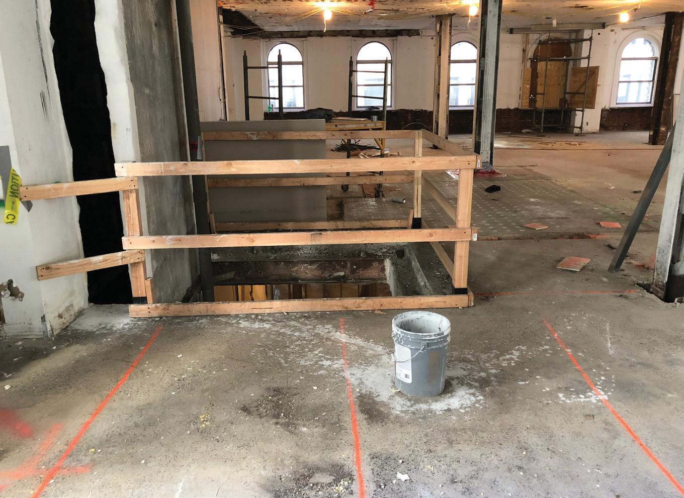
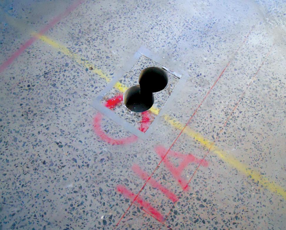
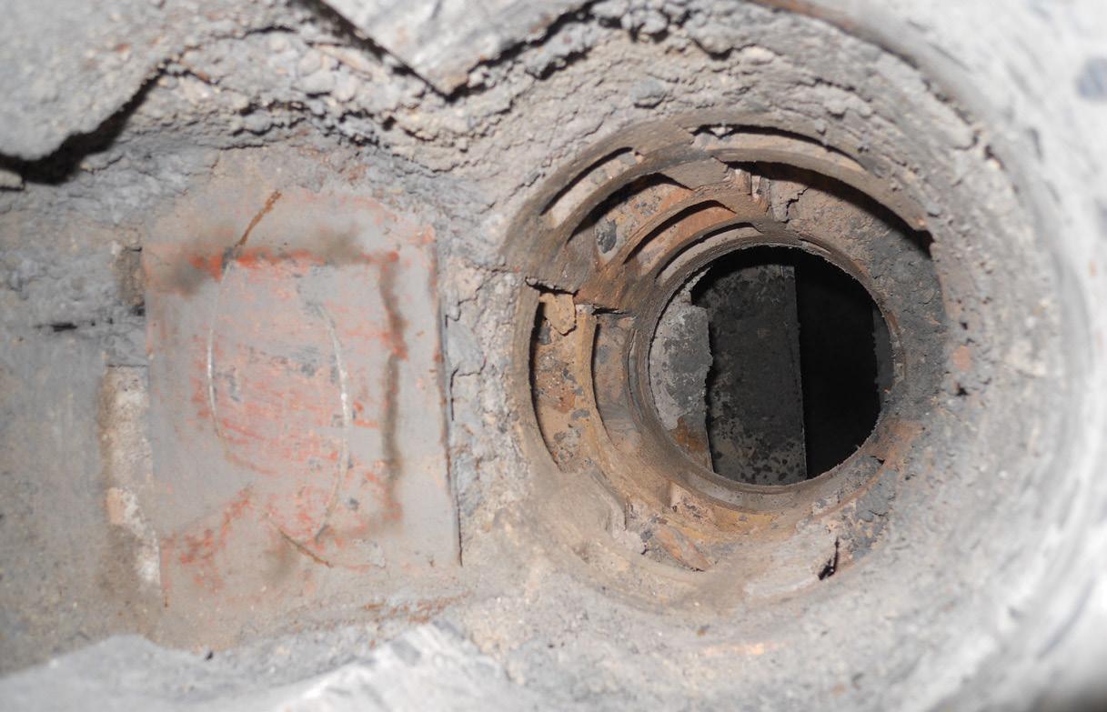
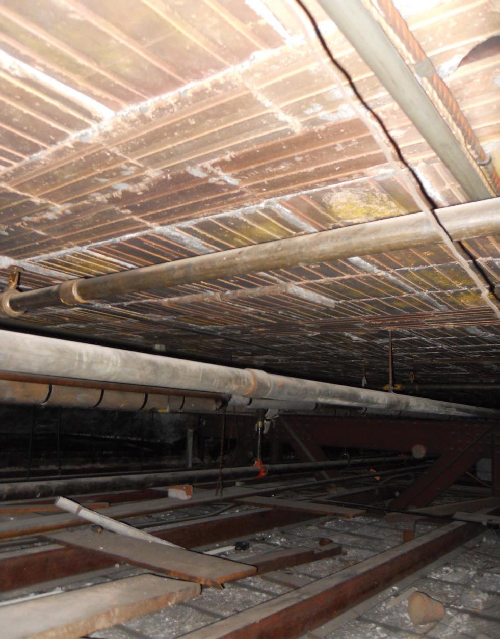
As a result, independently supported loft floor framing was designed using ¾-inch Structural Panel concrete subflooring manufactured by USG. The subflooring spanned between cold-formed steel (CFS) joists supported by new wide flange steel beams that spanned between the existing Gray building columns. The 5% maximum gravity load increase allowed by the International Existing Building Code (IEBC) was used to justify the additional mezzanine loads imposed on the existing columns. Similarly, proposed loft areas associated with the 2nd-floor residential areas had to also be supported by new steel beams spanning between the existing building columns. This is because the assumed existing 100 psf capacity of the second floor was less than the anticipated combined loads of the same multi-level residential areas. However, this aspect of the adaptive reuse plan was not constructed due to limited headroom at the 2nd floor. The original adaptive reuse plan also included constructing a new rooftop deck assembly area and related enclosed elevator lobby and separate stair access areas. It was anticipated that new, exposed steel rooftop dunnage framing would span between the existing main building columns, as required to provide the minimum assembly live load capacity of 100 psf. In addition, new stair and elevator penthouses were required to provide access from the 11th floor. However, the new rooftop features were excluded from the project due to the excessive cost of the proposed renovations. Additional adaptive reuse features that impacted the existing structure included a new trash chute and mechanical chase from the 2nd to the 11th floor. In addition, the new mechanical chase extended up through the 11th-floor attic and roof framing. Due to the susceptibility of flat, hollow clay tile construction to penetrations, it was anticipated that these large new openings would involve re-support of the affected arch framing. Also, it was anticipated that the interruption of any existing tie rods used as part of flat arch tile construction that occurred within the new openings would require that the adjacent affected interior arch spans be strengthened. For reasons similar to that described above for the new floor and roof openings, it was anticipated that smaller utility holes required for the new residential bathrooms and kitchens could potentially also
Figure 7. Typical cored hole penetration in a hollow clay tile floor. require strengthening of the flat, tile arch construction. However, it was expected that the strengthening, as long as a tie rod was not interrupted, would only involve installing small steel compression frames that would enable the continuity of the surrounding flat arch clay tile units at the new penetrations (Figure F, online). In addition, it was anticipated that penetrations that only involved small, cored holes would be allowed without reinforcing the tile if the penetrations could be located to minimize damage to the affected individual tile (Figure G, online). At similar existing holes that were no longer needed, the opening and surrounding cavities of the affected hollow clay tiles were simply infilled with lightweight concrete. Lastly, it was also anticipated that infilling the large existing opening in the floors associated with the mechanical penthouse shaft (Figure 7), added during the life of the building, would be required. This was accomplished by constructing new concrete slabs on metal deck that were supported by new steel beams spanning between the existing floor beams. The capacity of the existing steel beams around the perimeter of the openings to support the new dead and live loads associated with the infill framing was also confirmed.
As a part of the initial project design and ongoing adaptive reuse construction during the project, several investigations were conducted to better understand the existing structure without any existing drawings. A summary of the major investigations completed is provided below. 1st, 5th, and 11th Floor Framing
Investigations of the typical fl oor framing at the 1st, 5th, and 11th fl oors were conducted to confi rm the load-carrying capacity of the existing Carnegie steel beams. e investigations concentrated on the steel beams rather than the hollow clay tiles because of the diffi culty and cost associated with locating and measuring the tie rods used with this type of masonry fl at arch framing, which is the most accurate method of estimating the load-carrying capacity of this same framing system. In addition, it is common for the load-carrying capacity of a fl at tile arch to signifi cantly exceed that of the supporting beams because of the large safety factors utilized by the original designers for this type of system.
e investigation of the beams at the referenced fl oors was conducted in the following manner. Because the beams were concealed by the existing fl oor fi nishes and the plaster ceiling, it was necessary fi rst to locate the beams via handheld ground penetrating radar (GPR). In addition, because of the presence of an existing ±5-inch-thick concrete topping, which also included embedded conduits, it was necessary to scan the beams with the GPR from the ceiling side of the framing where only a few inches of plaster and solid tile separated the steel beam fl ange from the exposed soffi t. Once the beams were located and the centerline of the members was accurately marked on the top of the fi nished fl oor, the slab was then cored directly on top of the wide fl ange Figure 10. Voussoir arched tiles on each side of and parallel and directly beneath the concealed steel beams. section to reveal the beam width. A second core was then taken through the entire depth of the topping and tile immediately adjacent to the fl ange tip of the beam to confi rm the beam depth (Figures 8 and 9). Both of the core locations allowed the dimensions of the steel section to be accurately recorded and the thickness of the concrete topping, hollow clay tile, and plaster ceiling to be
ADVERTISEMENT–For Advertiser Information, visit STRUCTUREmag.org

Now you can eliminate pour strips - and the extra costs, construction delays, and safety issues they bring - with the PS=Ø® Steel Reinforcement Splice System.
PS=Ø®: • Reduces costs • Accelerates construction • Improves safety • No leave-outs • No redesign • ACI Type 1 & Type 2 • ICC-approved • Made in the USA
PS=Ø® is a steel reinforcement splicing system that eliminates pour strips and maintains rebar continuity while allowing for volume change. PS=Ø® stands for pour strip zero and utilizes proven technologies with a tapered thread on one end and a grout-filled sleeve on the other.


documented. It was not necessary to confirm the thickness of the tapered I beam flanges because the available Carnegie Steel section property tables (Figure H, online) only included dimensions for the beam depth and flange width and not the variable flange thickness. The reserve load-carrying capacity of the floor beams at all three levels was determined to be approximately 100 psf based on the yield strength of the Carnegie beams documented as a part of the Main Roof and Original Mechanical Penthouse investigation described below. Main Roof and Original Mechanical Penthouse
As indicated above, the original adaptive reuse plan for the building included constructing an open-air rooftop assembly space and a new access elevator and stair from the 11th floor for use by the residents. As a result, it was necessary to conduct a structural investigation to determine the load-carrying capacity of the affected roof framing. As previously described, due to the termination of the interior building columns at the 11th floor at the north end of the building, existing fabricated steel roof trusses clear spanned between the main east and west sides of the building to support the main roof, original rooftop mechanical penthouse high roof and floor, and the 11th-floor ceiling framing. Therefore, the intent of the investigation involved determining the reserve load-carrying capacity of a typical steel roof truss, high penthouse roof steel purlin and beam, and main roof steel beam. The findings of the investigation are provided below and were based on the results of a steel coupon test of a penthouse roof purlin that indicated an approximate yield strength of 32 ksi. The sample was taken from a portion of the bottom flange at the end of the span next to a supporting column. In addition, the location of the main
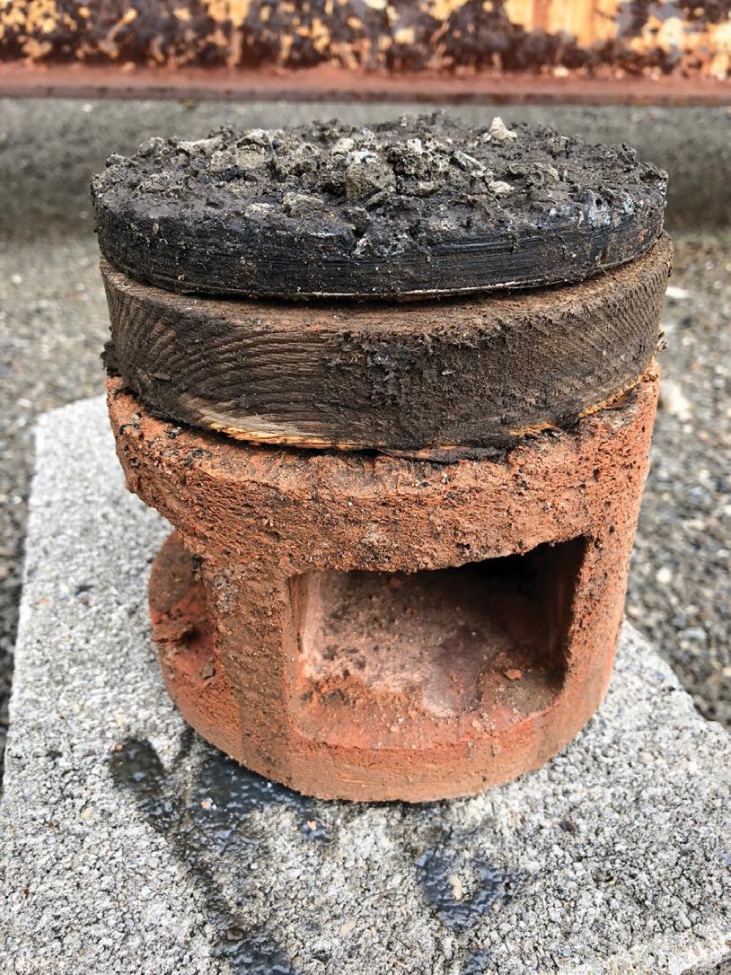
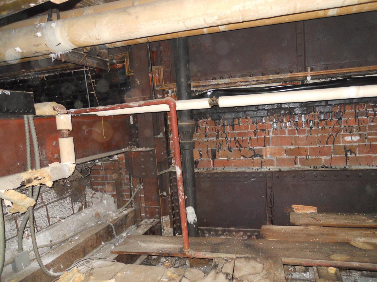
roof beams and the direction of span of both the beams and tile arch were visible from the 11th-floor attic framing because plaster had not been applied to the tile soffit. As a result, the scored bottoms of the 12-inch-wide by 9-inch-long (in the direction of the arch span) hollow clay tiles were visible, with the beam locations identified by the scored bottoms of the end voussoir and beam soffit tiles arranged parallel to and centered about the entire beam span (Figure 10). Similarly, because the soffit of the high penthouse roof had not been plastered, the location and direction of span of book tiles, bulb tees, purlins, and beams were also readily apparent. In addition, full-depth cores were taken at both the high penthouse and main roofs to confirm the thickness of the 4-inch book tiles (Figure 11) and 12-inch-depth hollow clay tiles, respectfully, and the associated existing roofing. Figure 11. Mechanical penthouse high roof 4-inch hollow As indicated in Part 1 of this article, the clay book tile core. southern portion of the main roof was not framed with trusses and instead was constructed with Carnegie Steel B Beams and built-up, riveted steel plate and angle girders as shown in Figure 12. This area of the building was subsequently investigated as a part of the Mechanical Penthouse and Cooling Tower Dunnage investigation that will be provided in Part 3 of the article. High Mechanical Penthouse Roof Framing The analysis of the exposed high roof steel beams indicated that the framing had a reserve load carrying capacity of approximately 50 psf in addition to the current-day code-minimum flat roof snow load. This maximum load was based on the capacity of the beams; however, the purlins had a reserve load-carrying capacity of approximately 75 psf. Therefore, a determination of the load-carrying capacity of the book tiles and supporting bulb tees was not performed. Main Roof Framing
Only the 10-inch-deep north-south support beam along the east wall of the mechanical penthouse could be measured and therefore analyzed. The results of this analysis indicated that the member only had a reserve load carrying capacity of approximately 10 psf in addition to the current day code minimum flat roof live load, including snow drift loads.
Typical Roof Truss
The results of the analysis of a typical Warren roof truss (Figure I and J, online) indicated that the member did not have reserve capacity to support the proposed new rooftop assembly space deck; however, it did have adequate capacity to support the reserve capacities noted above for the penthouse high and main roof framing. Part 3 of this series includes a continuation of the structural investigation, specifically regarding the main roof and original mechanical penthouse.■
D. Matthew Stuart is Senior Structural Engineer at Pennoni Associates Inc. in Philadelphia, PA. (mstuart@pennoni.com)


