12 minute read
Building Blocks
Part 1
By James LaBelle, P.E., Doc.E.
This is Part 1 of a two-part series. This installment summarizes two methods of determining available strengths from testing of aluminum structures, presents equations, and includes selected plots of calculated safety factors. The next part will discuss and compare the results from the two methods.
Let’s say you have some test data for an aluminum component or structure. Will it make a difference which method is used to establish an available strength with that data? In the Aluminum Association’s 2020 Aluminum Design Manual, Part 1 – Specification for Aluminum Structures (Appendix 1: Testing [§1.3]), there are two methods for determining available strength from test data. This study included both the Allowable Strength Design (ASD) and Load and Resistance Factor Design (LRFD) procedures to compare the results from these two methods. This was an analytical study only – no tests were conducted. However, the author’s prior use of these two methods, for a few individual sets of test data, indicated that allowable strengths from Method 1 tended to be more conservative than those from Method 2.
The number of samples considered ranged from 7 to 50 and the coefficient of variation from 4% to 20%. For Method 1, safety and resistance factors from the Specification are applied to calculated nominal strength values based on test statistics. Method 2
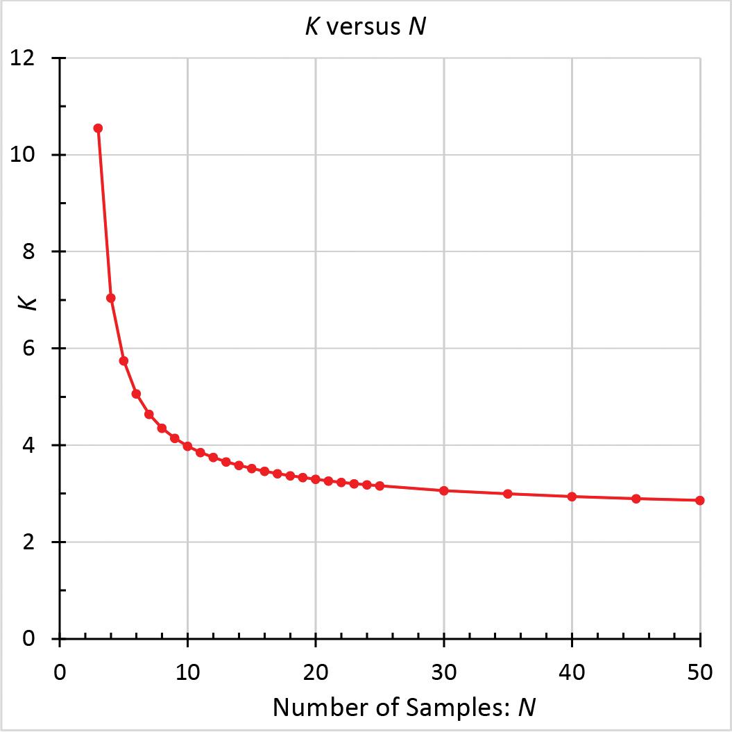
Figure 1. Statistical coefficient (K) vs. the number of samples (N).
available strengths are found by applying calculated (using test statistics and other parameters) safety and resistance factors to test averages. Of the many possible input values for Method 2, the current study was restricted to default values for the parameters. Plots of Method 2’s calculated safety factors provide a sense of the wide range of possible values. For the set of variables considered, this study (including Part 2) shows that available strengths based on Method 1 are generally, but not in all cases, less (by widely varying percentages) than corresponding values from Method 2.
Method 1
This method is simpler to use than Method 2 and has fewer input parameters. As given in the Specification for various limit states, the pertinent safety factors (Ω) for ASD range from 1.95 to 3.0, and the resistance factors (φ) for LRFD from 0.75 to 0.50. To find the allowable strength (R1Ω), this method uses a calculated nominal strength (RN1), which per Method 1 is based on test statistics, divided by a safety factor chosen separately depending on the limit state. Similarly, the design strength (R1Φ) is the product of the resistance factor and RN1. The nominal strength (RN1) is a statistical lower bound (99% exceedance, with 95% confidence) on strength, which is based on test average (RTM), sample standard deviation (σx), and a statistical coefficient (K; Figure 1) that is based on the number of samples (N). Minimum N is 3. For 7 ≤ N ≤ 50, K varies from 4.641 to 2.863. K accounts for uncertainty about the possible difference between the sample and population
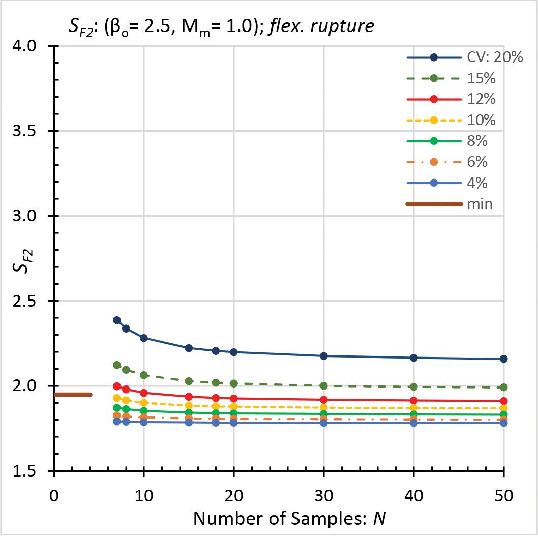
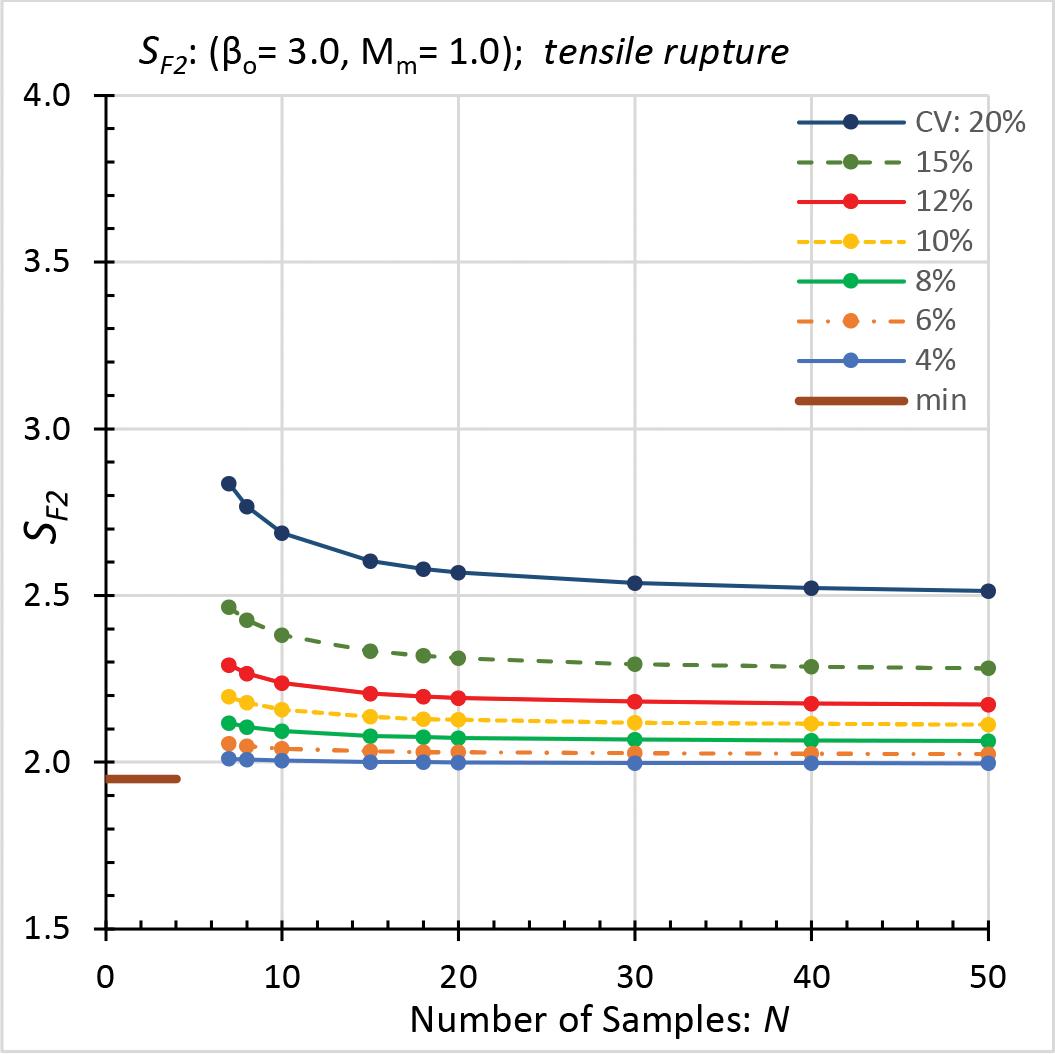
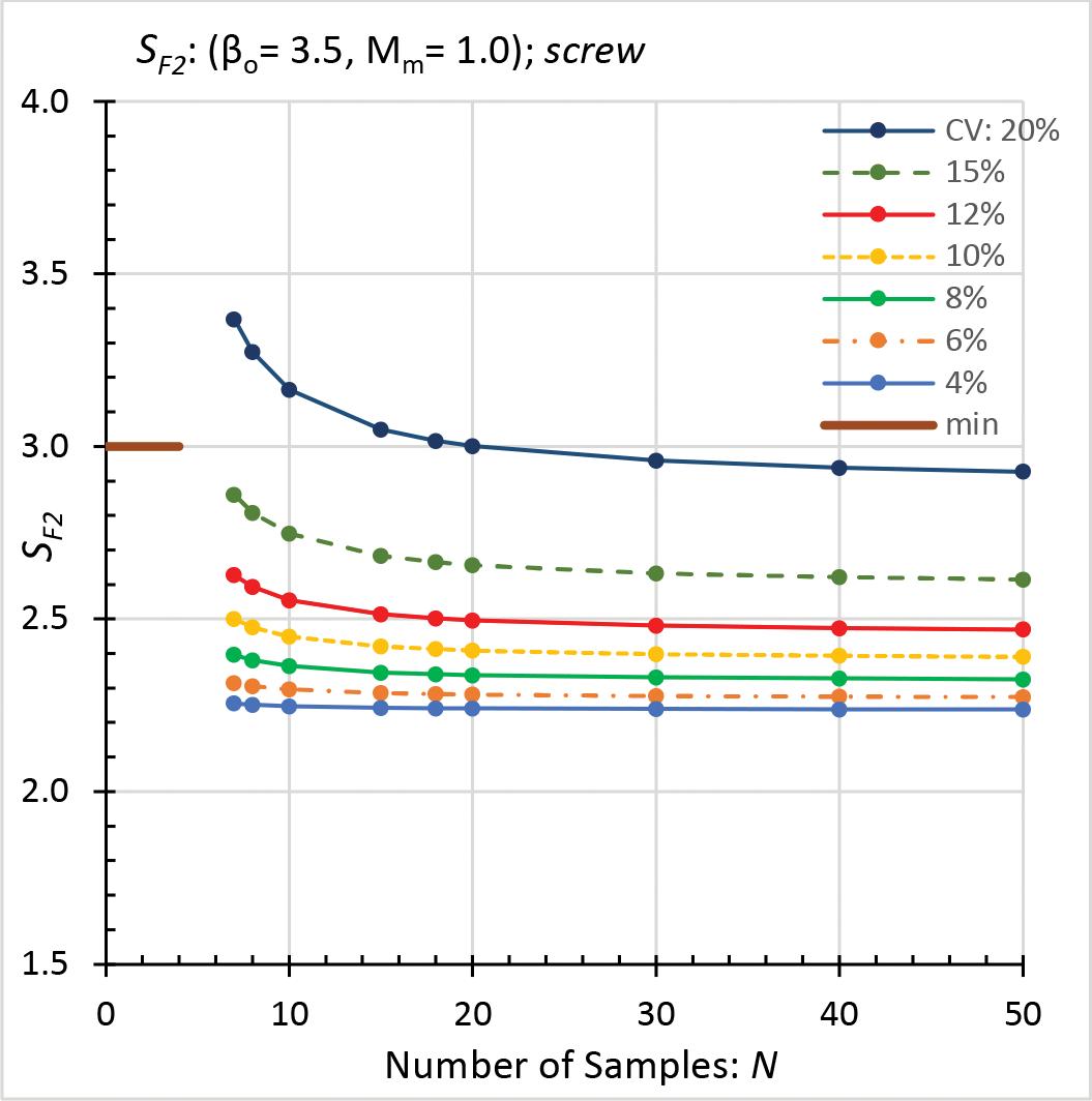
Figure 3. Safety factor SF2: rupture of tension members. Figure 4. Safety factor SF2: tapping-screw connections.
standard deviations; it increases at an increasing rate as N becomes smaller, especially for N less than about 20. To compare Method 1 available strengths with Method 2 available strengths, for ASD and LRFD, the applicable equation for the nondimensional ratio of available strength to average test strength was determined for each method. Variables include:
K = statistical coefficient
N = number of samples
RN1 = calculated nominal strength
RTM = test mean (average) strength σx = sample standard deviation φ = resistance factor for LRFD
Ω = safety factor for ASD The Method 1 allowable strength (ASD) is:
R1Ω = RN1 / Ω = (RTM - Kσx) / Ω (Eqn. 1) Now divide the allowable strength by the test average. Note that the coefficient of variation CV = σx / RTM:
R1Ω / RTM = (1 - KCV) / Ω (Eqn. 2) The Method 1 design strength (LRFD) is:
R1Φ = φRN1 = φ (RTM - Kσx) (Eqn. 3) Divide the design strength by the test average:
R1Φ / RTM = φ (1 - KCV) (Eqn. 4)
Method 2
See the Specification for further Method 2 details. As an example, this method had previously been applied to data for screw pull-out from screw chases. For the current more general study, the default values of various parameters were employed: • α (= 0.2): dead-to-live load ratio • Mm (= 1.00 for rupture): material factor • Fm (= 1.00): fabrication factor • VM (= 0.06): material variation
• VF (= 0.05 for structural members and mechanically fastened connections; 0.15 for welded connections): fabrication variation • VQ (= 0.21): load variation • βo (= 2.5 for beams and columns, 3.0 for tension members and 3.5 for connections): target reliability index. To determine allowable strengths (R2SF) for Method 2, the average test strength is divided by a calculated safety factor (but not less than a minimum), which depends on many statistical variables. To distinguish the safety factor (Ω) in Method 1 from that in Method 2, the notation SF2 is used here for the Method 2 safety factor.
SF2 = eψ (1.05α + 1) / [MmFm (α + 1)] (Eqn. 5) where, ψ = βo (VM 2 + VF 2 + CNVP
2 + VQ 2 )0.5 Here, VP = CV, which is the coefficient of variation for the test results, and CN = (N 2–1) / (N 2–3N ). The minimum N is 4. For ASD, SF2* is the greater of SF2 and the applicable value of Ω in the Specification. The allowable strength is:
R2SF = RTM / SF2 * (Eqn. 6) For Method 2, the ratio of the allowable strength to the test average is:
R2SF / RTM = 1 / SF2* (Eqn. 7) The calculated resistance factor in Method 2 is denoted here as φ2 to distinguish it from the resistance factor (φ) used in Method 1. φ2 = 1.5 MmFm / e ψ (Eqn. 8) For LRFD, φ2* is the lesser of φ2 and the applicable value of φ in the Specification. The design strength is:
R2Φ = φ2* RTM (Eqn. 9) For Method 2, the ratio of the design strength to the test average is:
R2Φ / RTM = φ2* (Eqn.10) Safety Factors
Plots of calculated safety factors (SF2) and the required minimums are shown in Figures 2 through 5. Each plot is based on a different
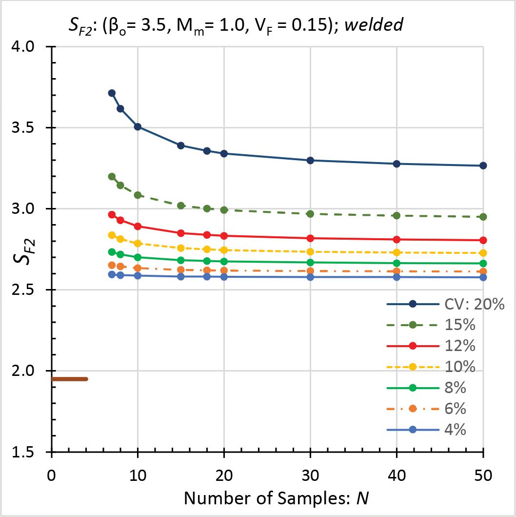
Figure 5. Safety factor SF2: welded connections.
combination of βo, Mm, and VF. VF equals 0.05, except for Figure 5, where it is 0.15. SF2 decreases as N increases (CV constant) and as CV decreases (N constant) for all plots. For large N and small CV, the decrease in SF is imperceptible in the figures. In these figures, a small number of samples (combined with intermediate or large CV values), or a large CV, typically results in a relatively large SF2. In each Figure, the range of calculated safety factors (SF2) is: • Figure 2 (beam rupture): 2.39 to 1.78, but the required minimum is 1.95. • Figure 3 (rupture of tension members): 2.84 to 2.00, which exceeds the minimum of 1.95. • Figure 4 (tapping-screw connections): 3.37 to 2.24, but the minimum is 3.0, which governs over most of the calculated values. • Figure 5 (welded connections): 3.71 to 2.58, all of which exceed the minimum of 1.95. Where a calculated safety factor (SF2) exceeds the corresponding minimum (Ω), then SF2* equals SF2. In this case, Method 2 determines an allowable strength that is less than RTM / Ω. Resistance Factors
Plots are not shown for calculated resistance factors (φ2), but the Table provides a sampling of results for each condition. If a calculated resistance factor (φ2) is less than the corresponding upper limit (φ), then φ2* equals φ2. In this situation, Method 2 provides a design strength that is less than φRTM. For both ASD and LRFD in Method 2, the available strengths are based on the test averages. However, the main body of the Specification bases available strengths on nominal strengths (RN), which are in most cases less than test averages. This means that a test average divided by SF2* could produce an allowable strength that exceeds RN / Ω. Similarly, a test average multiplied by φ2* could result in a design strength that is greater than φRN. Method 1 vs. Method 2
Note that KCV > 0 for CV > 0. Given this, Equation 2 (Method 1’s ratio of allowable strength to test average) is less than Equation 7 (Method 2’s ratio for allowable strength) if SF2* equals Ω. Similarly, Equation 4 (Method 1’s ratio of design strength to test average) is less than Equation 10 (Method 2’s ratio for design strength) if φ2* equals φ.
Acknowledgments
The author acknowledges the constructive comments during article preparation from J. Randolph Kissell, P.E., and Scott Walbridge, Ph.D., P.Eng.■
References are included in the online PDF version of the article at STRUCTUREmag.org.
James LaBelle is a Consultant with experience in the design and investigation of aluminum and other structures. He is retired from CSD Structural Engineers, Milwaukee, WI, and is a member of the Aluminum Association’s Engineering Design Task Force, FGIA (formerly AAMA), and ASTM. (jlabelle@csd-eng.com)
Table of bounding values of φ2 for LRFD.
Case Calculated φ2 Upper limit
Min. Max.
Beam Rupture 0.63 0.85 0.75
Tension-Member Rupture 0.53 0.76 0.75
Tapping-Screw Connections 0.45 0.68 0.50
Welded Connection 0.41 0.59 0.75 Comment
Limit < max
Limit < max
Limit < max
Max < limit
Adhesives Technologies Corporation
Phone: 754-399-1057 Email: atcinfo@atcepoxy.com Web: www.atcepoxy.com Product: ULTRABOND® Anchoring and Doweling Adhesives Description: America’s #1 structural adhesive specialist off ers four IBC compliant adhesives. HS-1CC, the world’s strongest anchoring epoxy. New EPX-3CC high-performance epoxy for high-volume applications. New HYB-2CC hybrid cures fast in hot and cold temperatures. ACRYL8CC cures fast with a very broad application temperature range. ATC is a Meridian Adhesives Group Company.
Adit Ltd
Phone: 00-972-77-5020696 Email: offi ce@adit.org.il Web: www.adit.org.il Product: Adit Design Anchor Guide 2021 Description: Designing internationally? e Guide allows you to easily consult all the factors used to design anchors in a user-friendly environment. e new version is only available in Hebrew and can be downloaded from the website.
ASDIP Structural Software
Phone: 407-284-9202 Email: support@asdipsoft.com Web: www.asdipsoft.com Product: ASDIP STEEL Description: Includes the design of biaxial base plates, anchor rods, and shear lugs, per ACI 318-19. Easily generate detailed reports for complex anchorage design calculations, including the ACI seismic provisions. Both ASD and LRFD can be specifi ed. Load combinations per ASCE 7-05, ASCE 7-10/16, or user-defi ned. IES, Inc.
Phone: 800-707-0816 Email: info@iesweb.com Web: www.iesweb.com Product: VAConnect Description: Design base plates by AISC Design Guide #1 and anchorage calculations for ACI 318. Both, independently, are diffi cult by hand! With VAConnect you will get the job done quickly and accurately. Works alone or with IES VisualAnalysis.
National Council of Examiners for Engineering and Surveying
Phone: 800-250-3196 Email: jbarker@ncees.org Web: ncees.org Product: Professional Engineering License Description: e National Council of Examiners for Engineering and Surveying (NCEES) is a nonprofi t organization dedicated to advancing professional licensure for engineers and surveyors.
RISA
Phone: 949-951-5815 Email: benf@risa.com Web: risa.com Product: RISAConnection Description: e cutting edge of next-generation connection design software. Features full 3-D visualization, as well as expandable reports for every limit state. In addition to steel connection design, RISAConnection includes integration with Hilti Profi s for the design of base plates, as well as concrete anchorage design according to American code. Trimble
Phone: 678-737-7379 Email: jodi.hendrixson@trimble.com Web: www.tekla.com/us Product: Tekla Tedds Description: Automating your every day structural designs, the Tekla Tekla Tedds’ library includes anchor bolt design per ACI 318 Appendix D. e calculation includes comprehensive checks for tensile and shear failure of anchors and is available as part of a free trial by visiting the website.
Product: Tekla Structural Designer Description: Engineers have the power to analyze and design multi-material buildings effi ciently and costeff ectively with Tekla Structural Designer. Physical, information-rich models contain all the intelligence needed to fully automate design and document projects, including end force reactions communicated with two-way BIM integration, comprehensive reports, and drawings.
Product: Tekla Structures Description: An Open BIM modeling software that can model all types of anchors required to create a 100% constructible 3-D model. Anchors can be created inside the software or imported directly from vendors that provide 3-D CAD fi les of their products.
Williams Form Engineering Corp.
Phone: 616-866-0815 Email: williams@williamsform.com Web: www.williamsform.com Product: Anchor Systems Description: Williams Form Engineering Corporation has been providing threaded steel bars and accessories for rock anchors, soil anchors, high capacity concrete anchors, micropiles, tie rods, tiebacks, strand anchors, hollow bar anchors, post tensioning systems, and concrete forming hardware systems in the construction industry for over 95 years.
DEWALT Anchors and Fasteners
Phone: 800-524-3244 Email: anchors@DEWALT.com Web: http://anchors.dewalt.com/anchors Product: CCU+ Critical Connection Undercut™ Description: DEWALT Anchors and Fasteners launches a new heavy-duty concrete anchor for use in critical applications where a robust anchor with low displacement is necessary. e CCU+ Critical Connection Undercut is ICC-ES qualifi ed under ESR-4810 for use in cracked and uncracked concrete. e anchors are Made in the USA.
ENERCALC, Inc.
Phone: 800-424-2252 Email: info@enercalc.com Web: https://enercalc.com Product: ENERCALC Structural Engineering Library Description: Our latest improvements to SEL include our new Flitch Plated Wood Beam module and new Steel Base Plate by FEM. Both modules can help designers refi ne their design loads on the anchor rods, common bolts, and framing anchors. Structural Engineering Library subscriptions now provide both installed and cloud use.
ENERCAL C
Listings are provided as a courtesy, STRUCTURE is not responsible for errors.
Demos at www.struware.com
Wind, Seismic, Snow, Rain, etc. Struware’s Code Search program calculates these and other loadings for all codes based on the IBC or ASCE7 in just minutes (see online video). Also calculates wind loads on rooftop equipment, signs, walls, chimneys, trussed towers, tanks and more. ($295.00). CMU or Tilt-up Concrete Walls Analyze solid walls for out of plane loading and panel legs next to or between openings by automatically calculating loads to the wall leg from vertical and horizontal loads at the opening. ($75.00 ea) Floor Vibration Program to analyze floors with steel beams and/or steel joist. Compare up to 4 systems side by side ($75.00). Concrete beam/slab Program to provide bending, shear and/or torsional reinforcing. Quick and easy to use ($45.00).


