28 minute read
Historic Structures
The Point Ellice Bridge Failure By Frank Griggs, Jr., Dist. M.ASCE, D.Eng, P.E., P.L.S.
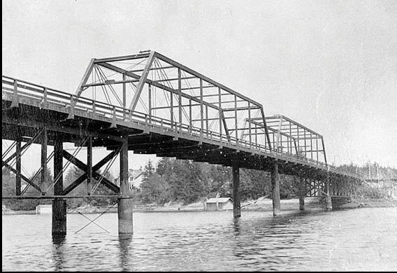
The Point Ellice Bridge crossed the Upper Harbor from Victoria, British Columbia, to Esquimalt. The first wooden pile bridge at the site was built in 1861 and was replaced in 1872. This was replaced by an iron bridge built in 1885 by the San Francisco Bridge Company for regular carriage, wagon, and pedestrian traffic. It was turned over to the City of Victoria by the Provincial Government in 1891. Engineering News described the bridge:
“It consisted of two 120-foot deck spans of Pratt combination trusses, 15 feet deep, with panels 17 feet 6 inches long; two 150-foot through spans of Whipple combination trusses, 25 feet deep, with eight panels 18 feet 9 inches long; and a short trestle approach…The piers were pairs of iron cylinders filled with concrete. The trusses were 20 feet apart, center to center, carrying a roadway 19 feet wide in the clear, with felloe or wheel guards 3 x 6 inches. Two 5-foot sidewalks were added after the bridge was commenced, each having three lines of 2- x 12-inch joists and 2- x 12-inch floor planks. The floor was about 20 feet above the water.”
Even though the trusses were iron, the entire deck was wood. Crossbeams on the 150-foot spans were 12 ×18 inches with wooden stringers. They were hung from the trusses with 1⅛-inch bars passing through the ends of the beams.
In 1889, The Victoria Tramway Company, later the Consolidated Electric Railway Company, obtained a charter to use the bridge for their streetcars, possibly without checking to see if the bridge was strong enough for additional loading. When the San Francisco Bridge Company heard of this, they visited the bridge. They determined the bridge was not designed for that loading, as they had used a static load of 600 pounds per foot and a rolling load of 1,000 pounds per foot in their design. However, they were told by the engineer of the Tramway Company that he had checked, and the bridge was safe. Initially, the Tramway Company had simply spiked iron straps to the planks and placed them close to one side of the bridge with a clearance at the outer rail of 2 feet 7 inches and a gauge of 5 feet. They added no additional stringers.
In 1893, one of the cross beams broke under their heaviest car, No. 16, and the deck sagged at the breakage. The city hired a local carpenter/blacksmith to repair the bridge. He replaced five of the seven beams with new 12- × 16-inch crossbeams on each of the 150-foot spans and 1¼-inch hangers with the ends upset to 1⅛ inch. The beams were drilled and notched to receive the bolts, cutting down on the strength of the ends of the beams. He left two existing beams in place, which proved to be penny wise and dollar foolish. At the same time, they replaced the straps with 30# T rails. These rails rested on two 10- × 12-inch stringers that were two panels long with broken joints.
May 26, 1896, was a day of celebration in Victoria, as people were celebrating Queen Victoria’s 76th birthday at a carnival in Esquimalt. The Consolidated Electric Railway Company ran additional cars to
Point Ellice Bridge. handle the number of people attending the festivities. They even brought out car No. 16, their heaviest at 16,000#, to handle the traffic. When the car with a capacity of 60 people, but now carrying 143, crossed the bridge, the span collapsed into the harbor. Evidently, one of the old wooden beams sheared off due to decay and reduced the section, which caused the car to tip side-wards and strike the iron truss work, which then collapsed, leading to the failure of the entire span. The car fell into the water with some of the truss falling behind it. Some of the passengers were killed by the falling ironwork, but most drowned. Of the estimated 143 passengers in the car, 55 died. A local report stated,
Those who are to blame are the “The central span of Point Ellice bridge had again given way, precipitatdesigners of structures and those who ing the car into the waters of the Arm, where a majority of the imprisoned employ them and insist on a trivial passengers – men, women, and little children – to whom the world had a moment before been all sunshine, were economy at the expense of safety. drowned before aid could reach them. The crashing timbers and ironwork of the bridge piled upon the ill-fated car as the waters received it, and doubling up, pierced it also from below so that many were killed even before the water was reached, while the others were less mercifully held below the muddy waters…So many victims as it claimed that there is scarcely a home in Victoria that has not lost some relative or friend. Ours is a city of desolation and of sadness, and in its mourning, Seattle, Tacoma, New Whatcom, Port Townsend, and the other cities of the Sound are joining, for each has contributed among the holidaymakers who formed the burden of the submerged car some of its well-known citizens.” A coroner’s inquest was held, and after interviews and investigation by the ten-man jury, found in part, “That the said accident was the result of the sudden collapse of the eastern Whipple truss of said bridge, and was caused by the weight of car No. 16 of the Consolidated Electric Railway Company and
its immense load of passengers, which was in excess of the capacity of the bridge in question as originally constructed, and that the said Consolidated Electric Railway Company is guilty of negligence in not having taken proper precautions for the safe conduct of its passengers accordingly; That car number 16 was dangerously overloaded with passengers, and in the interest of public safety, it is imperative that restrictions should be imposed upon the traffic of this and similar corporations in the future… Furthermore, it is manifestly the duty of all corporations of this kind who are entrusted with the safety of human lives to see that all roads and bridges over which it passes are in a safe condition and to take such steps as are necessary to ensure this condition of things being carried on by the proper authorities… That the bridge in question was adequate in strength to the ordinary traffic for which it was constructed and was under ordinary circumstances suitable for the ordinary railway traffic for which the railway company obtained permission to use it from the government department for whom it was constructed; but the design was poor, the system of construction obsolete, and the contract was not carried out according to specification by the contractors. We desire to call attention to and to condemn the system of public works which has been, and we believe now is in vogue in the public works department of the city. We find that the city engineer and heads of departments under him who should be held personally responsible for the good and efficient execution of the details of their department are so hampered and interfered with by un-technical, elective superiors that they are without authority necessary to carry out their work, and are consequently without responsibility, which is certainly not conducive to good results… We find that the specifications call for weldless iron, but that the ironwork in almost all cases were welded, and in many cases of inferior quality, and that the factor of safety provided for in the specifications is of an unknown quantity. It is quite evident from the evidence produced before us that the primary cause of the accident was the breaking of one certain hanger, shown as number 5 on the diagram produced in evidence, resulting finally in the collapse of the bridge; said hanger being part of the original construction. We find therefore that the Consolidated Electric Railway Company are primarily responsible for the accident and that the city council is guilty of contributory negligence.” (Victoria Daily Colonist, June 13, 1896, 6) Engineering News ran a lengthy article on the collapse and wrote in part, "There are some lessons in this accident which those in responsible charge of bridge structures will do well to profit by. It appears that the bridge in question was built for ordinary highway traffic and was designed to carry a live load of 1,000 pounds per lineal foot. As the combined width of roadway and sidewalks was 31 feet, this was equivalent to a live load of only 32 pounds per square foot, a figure which speaks for itself to any engineer. Manifestly the proper thing to do, if economy was necessary, was to narrow the roadway and sidewalks enough to enable the bridge to carry a crowd without exceeding the load per lineal foot for which it was designed. If a bridge is to be built of a strength suitable for a country highway, then it should be made of a corresponding width; but it is recklessness which cannot be too strongly characterized to make a bridge of a width for a city street and dimension its members as if it were of a width for a highway… It is not the bridge-building companies who are to blame for this dangerous economy in laying down live loads for structures. Every one of the bridge builders, we venture to say, would much prefer to build structures designed to carry the greatest load that can be placed
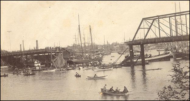
Failed 150-foot span, search for bodies underway.
upon them. Those who are to blame are the designers of structures and those who employ them and insist on a trivial economy at the expense of safety. We are aware that it is hard, oftentimes, for an engineer to stand up for what he knows is good and safe practice. To the average alderman, city councilor, or other layman, it may look like a piece of theoretical nonsense for the city engineer to insist on designing bridges to carry the weight of a crowd which may very probably never come upon the structure. But the only safe rule for the engineer, notwithstanding such opposition, is to stand out for what he knows to be safe and the only safe practice. We believe that the engineer who is in such difficulties may make good use of the descriptions of such accidents as that at Victoria, in this journal, to show to those who oppose him the results which may follow a neglect of sound engineering principles with respect to bridgework. The second point deserving attention, with respect to the Victoria bridge, is that although it was only designed for a live load of 1,000 pounds per lineal foot, several years after its erection, an electric car line was allowed to lay its tracks across the bridge, and no investigation, or at least no adequate investigation, was made to see whether the structure was strong enough to take the added load… Another point which may be noticed in this connection is the extent to which the overcrowding of cars is permitted on our street railways, and this has been a direct or indirect cause of many accidents, and the cause of much injury in many accidents not attributable in any way to overcrowding. The companies make little or no attempt to check this, or even to provide additional men in charge of the crowded cars, and some of them (whose roads carry enormous crowds of people) make the absurd claim that if the number of persons in the car was limited to its proper number or if they provided extra men, the profits would be so reduced that the company would have to go out of business. Such a claim cannot be seriously considered. In the accident at Victoria, noted above, about 140 persons were crowded in and upon a car seating only 60. Filling the standing room on days of exceptional traffic is permissible, according to universal American practice. But crowding passengers in cars without limit is barbarous and ought to be prevented by city authorities.” (Engineering News, June 18, 1896, 394) Court cases of the families of the killed ran on throughout 1897 and 1898 in the Supreme Court of British Columbia. The cases were finally settled in the Privy Council in June 1899 when the Railway was found liable for the deaths. In summary, the cause of the failure was likely the compounding of bad design, bad construction, lax inspection, and inadequate oversight of the electric railway operation.■
Dr. Frank Griggs, Jr. specializes in the restoration of historic bridges, having restored many 19 th Century cast and wrought iron bridges. He is now an Independent Consulting Engineer. (fgriggsjr@twc.com)

Wave One
A Story of TransfEr GirdErs
By Anantha Chittur, P.E., S.E., and Steven M. Baldridge, P.E., S.E.
The Near Capital Region (NCR) around India’s capital, New Delhi, witnessed a decade-long construction boom starting in 2008. Several high-rise apartments were constructed to cater to the growing need for housing in Noida, which was followed by new offi ce construction to lure large corporations away from the urban sprawl of New Delhi.
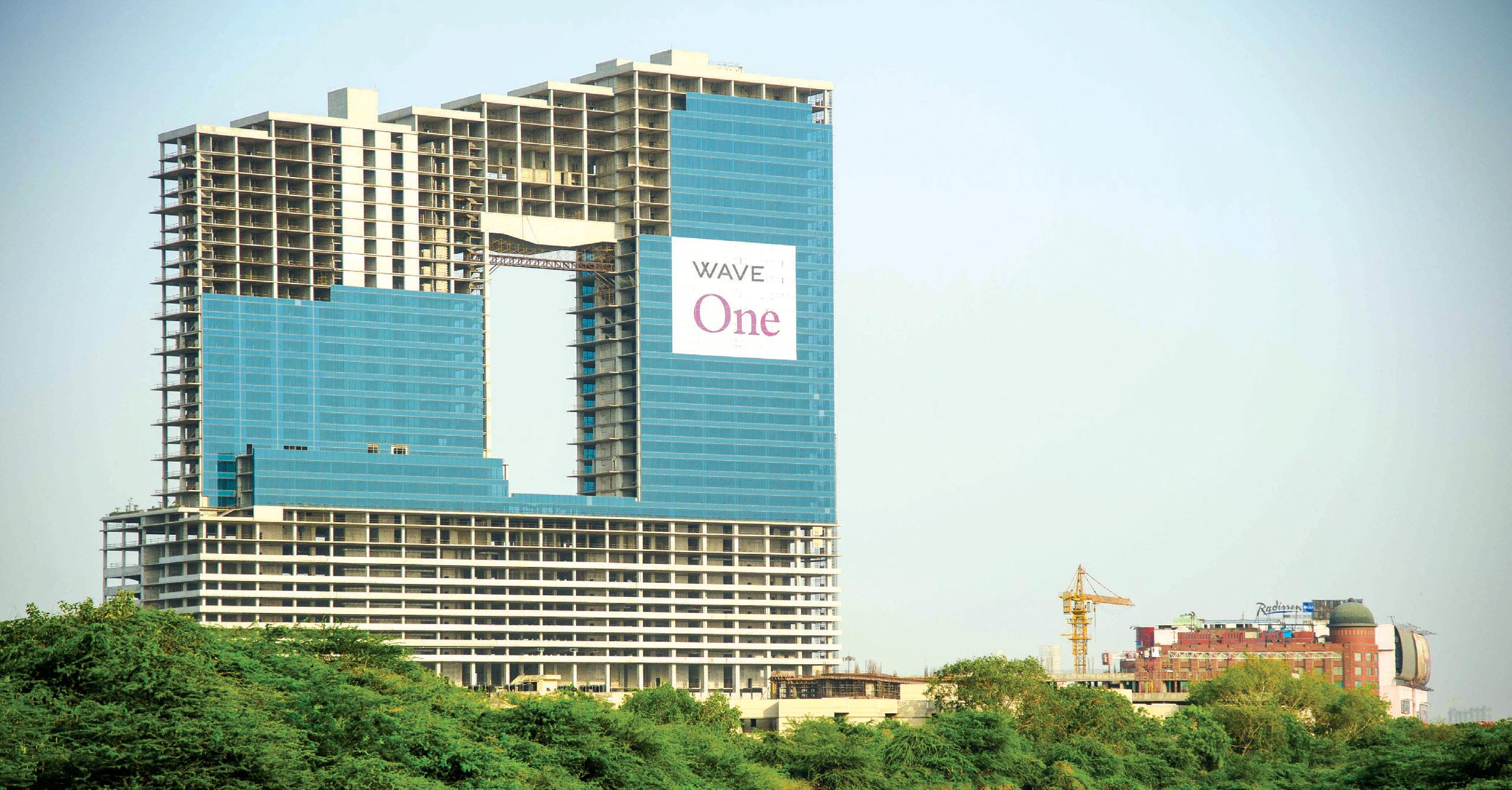
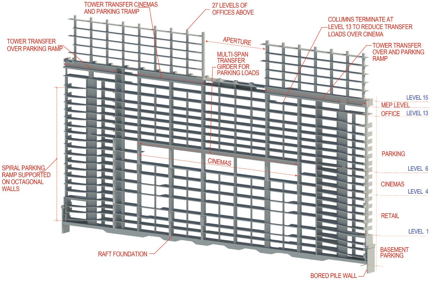
Wave One is a $276 million, 41-story mixed-use building with more than 2 million square feet of fl oor area located in the heart of Noida. It includes three levels of retail, two-story cinemas on the fourth fl oor, seven levels of parking above the cinema, and three levels of underground parking for a total of 2,600 cars. In addition, an extensive amenity deck, tennis courts, and a health club on Level 15 serve the tenants of the 26-story offi ce building that rises above the podium. e structure has a footprint of 528 feet by 228 feet on the podium levels and is constructed with no expansion joints. e building is characterized by a large rectangular aperture created to allow the “fl ow of energy” through the property. is aperture breaks the large offi ce mass into two distinct towers, which are reconnected between Levels 32 and 41. e project is located in a region of moderate high seismicity, requiring special detailing for concrete elements, including additional
checks for deformation compatibility of the slab-column gravity system. Shear walls at the cores provided lateral force resistance. The design is in accordance with India’s National Building Code (NBC) and other applicable local codes. Due to the building’s height and unique geometry, a wind tunnel study was conducted to determine the structural loads and occupant comfort.
Zero Lot Line Construction
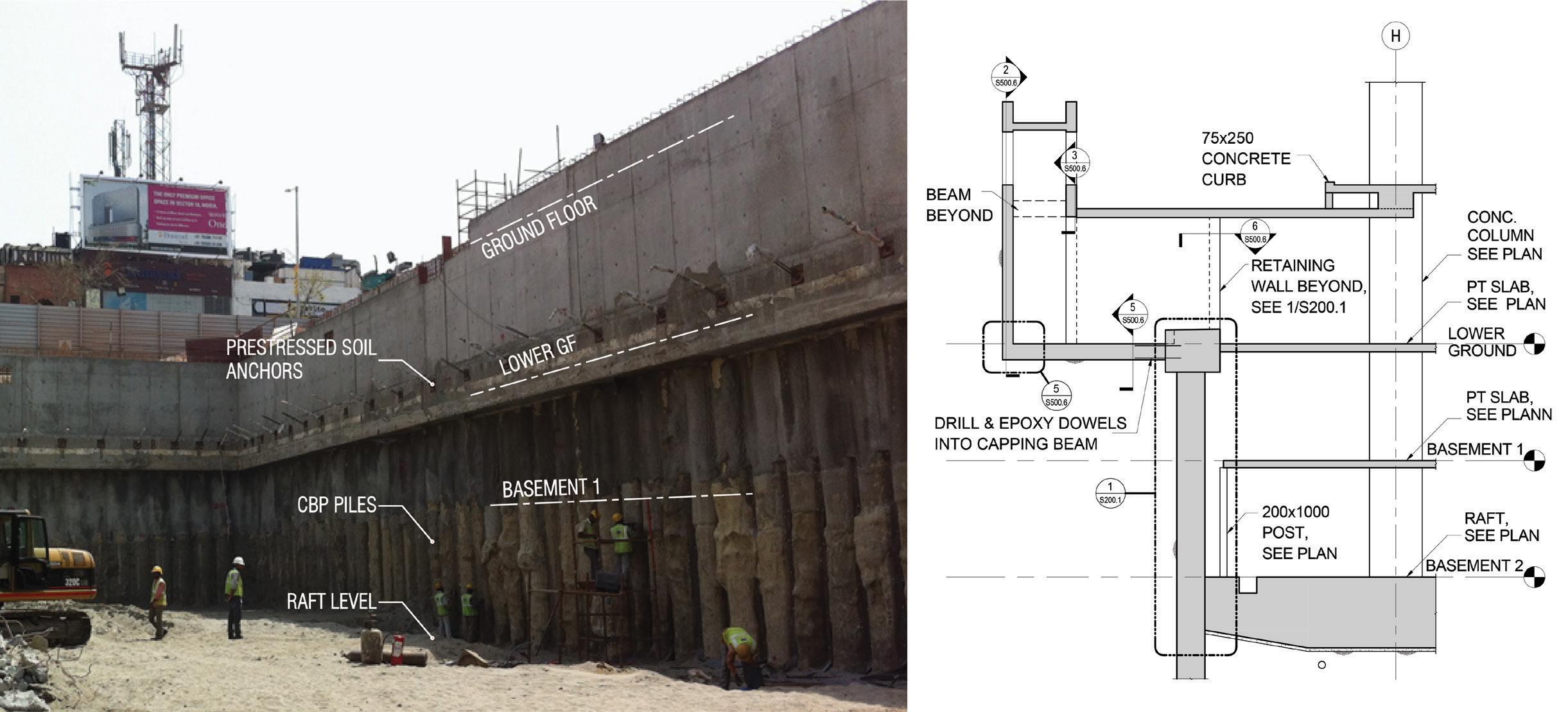
To maximize the building’s footprint, the basements are constructed with zero lot lines using a contiguous bored pile (CBP) wall earth retention system tied back using post-tensioned soil anchors until the basement slabs were installed. Traditionally, concrete retaining walls are constructed to act as the permanent structure in front of these piled walls. However, on this project, these CBP walls also act as a permanent earth retention system and support the basement slabs along the perimeter. In addition, masonry walls are built in front of the piled walls to conceal the drainage channels. This scheme resulted in a significant cost saving.
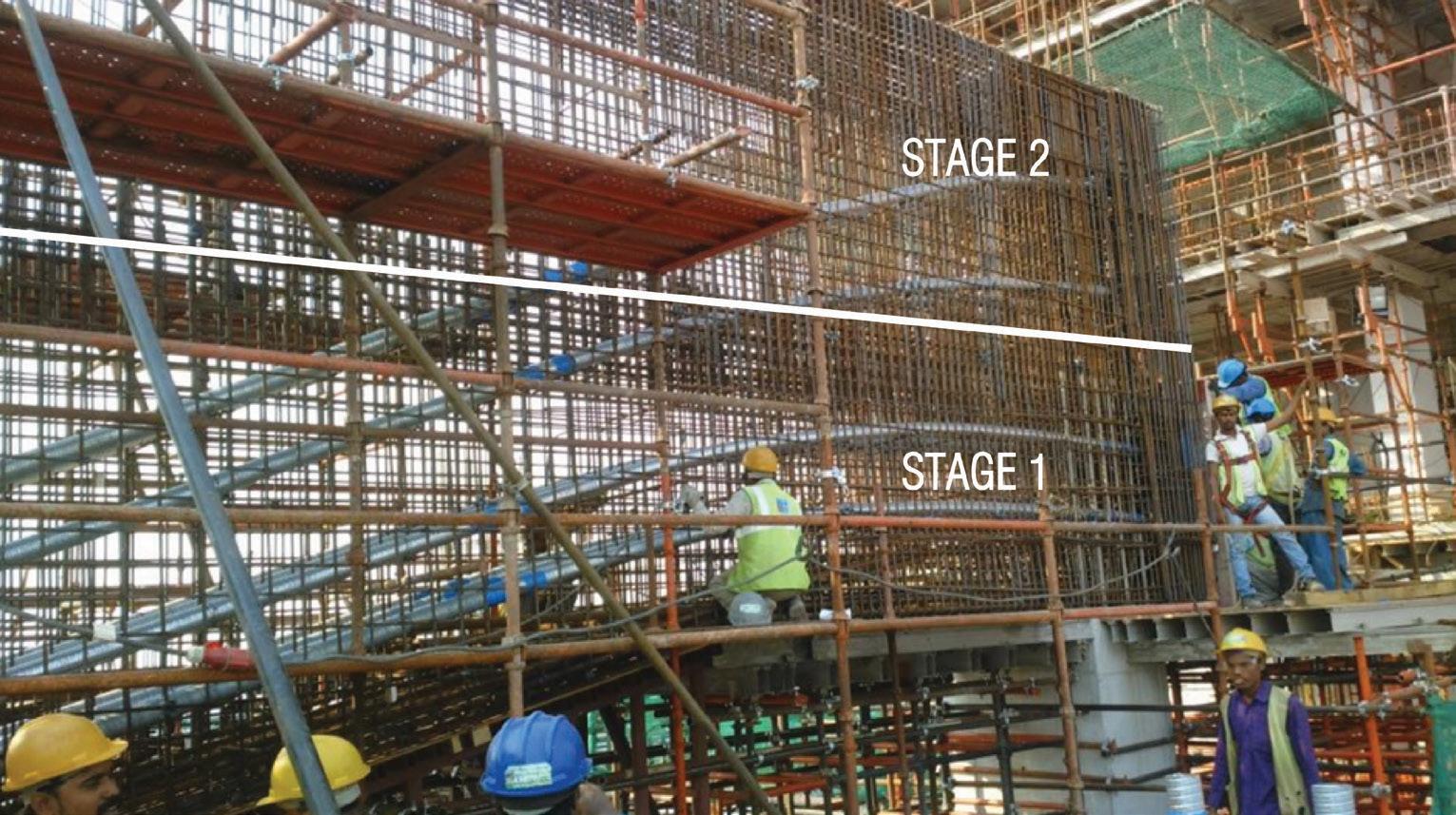
Two-stage transfer girder scheme.
Post-Tensioning as a Driver
Concrete is the material of choice for constructing buildings in India. When speed is a primary driver, as it was for this project, post-tensioned slabs and beams reign supreme. This is due to the load-balancing provided by the post-tensioning tendons that allow formwork to be removed and reused as soon as the tendons are stressed. When this project was conceived, post-tensioned concrete for buildings was in its nascency in India. It required a collaborative effort between the design team, contractor, and developer to devise the layout of vertical framing organized around an efficient post-tensioned slab system. The mixed-use building is apportioned into various uses such as parking, retail, offices, cinemas, outdoor amenities, mechanical floors, etc. The multi-story parking levels determined the layout of the columns in the podium, which, in turn, resulted in a square grid of 28 feet by 28 feet for the majority of areas, except for some longer spans at drive aisles. This layout also allowed the columns to continue vertically through the office levels with minimal impact. The typical slab thickness is 8 inches at the parking and office levels, while the retail levels have a thicker 9-inch slab. Traditionally, buildings in India are constructed with 2 to 3 inches of screed on top of the structural slab to allow for the lack of sophisticated finishing methods and allow tenants to pick their flooring as part of tenant improvement. However, on this design-assist project, it was decided to forgo the layer of screed on the parking levels due to the contractor’s ability to deliver a superior finished surface. In addition, the removal of the screed reduced the seismic mass of the building and helped to optimize the post-tensioned slab. The project’s scale and varied occupancies triggered a “Type 1” construction in accordance with the NBC, necessitating a 3-hour fire rating for

Aperture transfer girder.
the slabs. The conventional practice was to consider the concrete clear cover of 1⅜ inches to the post-tensioning duct even though the tendons are grouted and are often higher in the duct at midspan. BASE collaborated with the PT supplier to determine the elevation of the tendon within the duct, thereby gaining valuable drape in the tendon profile while still meeting the clear cover intent of the code.
Transfer Girders Galore
At Level 4 of the podium, above three levels of retail, the floor area was allocated for cinemas that required 56 feet by 84 feet of doubleheight, column-free space for each of the five cinemas. This could only be achieved through a five-span shallow post-tensioned transfer girder that spanned 56 feet while supporting seven levels of parking, one level of office, and one level of outdoor amenities. A portion of the office tower also hovered above the cinemas, requiring a different strategy to transfer the tower columns. The limited height available over the cinemas required a double transfer beam to support the office tower columns spanning between Levels 15 and 41. This was achieved by introducing one-story-deep transfer girders between Levels 14 and 15 and using the transfer beam over the cinemas to only support the podium loads. Due to the unique nature and length of the 280-foot multi-span transfer girder over the cinemas that were required along two column lines, the design team collaborated with the PT supplier to stress the tendons outside the cross-section of the girder. This facilitated pour strips and allowed the entire girder to be constructed simultaneously while also providing intermediate stressing to minimize post-tensioning losses. The external stressing strategy is often used in bridges but is not very common in buildings. BASE worked closely with the PT contractor and formwork subcontractor to minimize the number of reshoring levels by continuing the column removed in the cinemas as a low-strength sacrificial column supporting the transfer girder. This strategy enabled the early removal of beam formwork and three levels of reshoring below the transfer girder. Due to the zero lot line construction, the parking ramps are integrated within the building footprint. Two octagonal spiral ramps, one on each side of the building, provide vertical circulation for the parking levels. The ramps stop at the underside of Level 13 with 27 levels above it. Like the columns transferred over the cinemas, the tower columns above the ramp are supported on 6-foot-deep transfer girders extending between Levels 14 and 15. The total length of the transfer girder on Level 14 is 310 feet. The building’s characteristic rectangular aperture measures 200 feet by 103 feet and extends between Levels 15 and 32. The aperture is framed at the top by offices between Levels 32 and 41. The top of the building steps up from one end of the building to the other. The structure above the aperture is supported by three profiled posttensioned girders that span 112 feet between each tower. These sizeable concrete transfer girders were partly conceived due to the contractor’s desire to use a tried and tested construction methodology instead of introducing structural steel trusses. The contractor’s message to the design team was, “No Discovery Channel stuff, please.” However, the concrete option came with its own challenges from transfer girders that are 3.3 to 5 feet wide and constructed at 200 feet in the air. Due to the immense weight of the three transfer girders and the associated formwork requirements, the girders were shaped to reduce overall weight such that it was 20.5 feet deep in the middle to maximize drape and stiffness for the 112-foot span and 15 feet at the ends to satisfy shear requirements. Despite the shape optimization, the weight of wet concrete during placement would be problematic. BASE worked with the contractor and PT supplier to construct the beam in two segments with a horizontal construction joint with layered tendons that could be independently stressed. Once stressed, tendons in the lower half were designed to support the weight of the upper half during construction. Tendons in the second half were profiled such that maximum drape was utilized for final loading. The overall process was done in six stages: three bottom segments and three top segments.
Conclusion
A 2 million square foot high-rise project with multiple occupancies often comes with many challenges that require creative engineering solutions and close collaboration with the architect and other consultants. Post-tensioning often helps to simplify many of these problems by allowing for the removal, transfer, and shifting of columns and allowing slabs to span longer where required, giving the architect the desired flexibility.■
Anantha Chittur is a Senior Associate at BASE and is based in its Chicago office. (achittur@baseengr.com) Steven M. Baldridge is President at BASE and is based in its Honolulu office. (sb@baseengr.com)
Project Team
Owner: Wave Infratech Structural Engineer of Record: BASE Architect of Record: Nostri Architects Design Architect: BBG-BBGM General Contractor: Leighton-Infra Joint Venture Wind Tunnel Consultant: RWDI
This four-part series discusses the adaptive reuse of the Witherspoon Building in Philadelphia, PA. Part 1 includes the building history and description of the structure, including previous structural additions and alterations. In addition, numbered photos are provided with the print version of the articles, and additional lettered photos are provided with the online version of the articles.
Building History
The 11-story Witherspoon Building (not including full and sub-basement levels) is on the National and Philadelphia Registers of Historic Places. It is considered Philadelphia’s fi rst “skyscraper” and was constructed with Carnegie Steel beams between 1895 and 1897 for the Presbyterian Board and Sabbath School for use by various Presbyterian Church groups (Figure 1). As indicated on the available historical Sanborn Map for the building, the exterior brick masonry curtain wall varies in thickness from 28 inches to 12 inches, from bottom to top of the exterior façade, respectively. e Sanborn Map also indicates that the fl oors and roofs were framed with hollow clay tiles. e building was named for John Witherspoon, the fi rst president of Princeton University (then known as the College of New Jersey). It was designed by Architect Joseph M. Huston, a graduate of Princeton, and constructed by William Steele and Son, Carpenters and Builders.
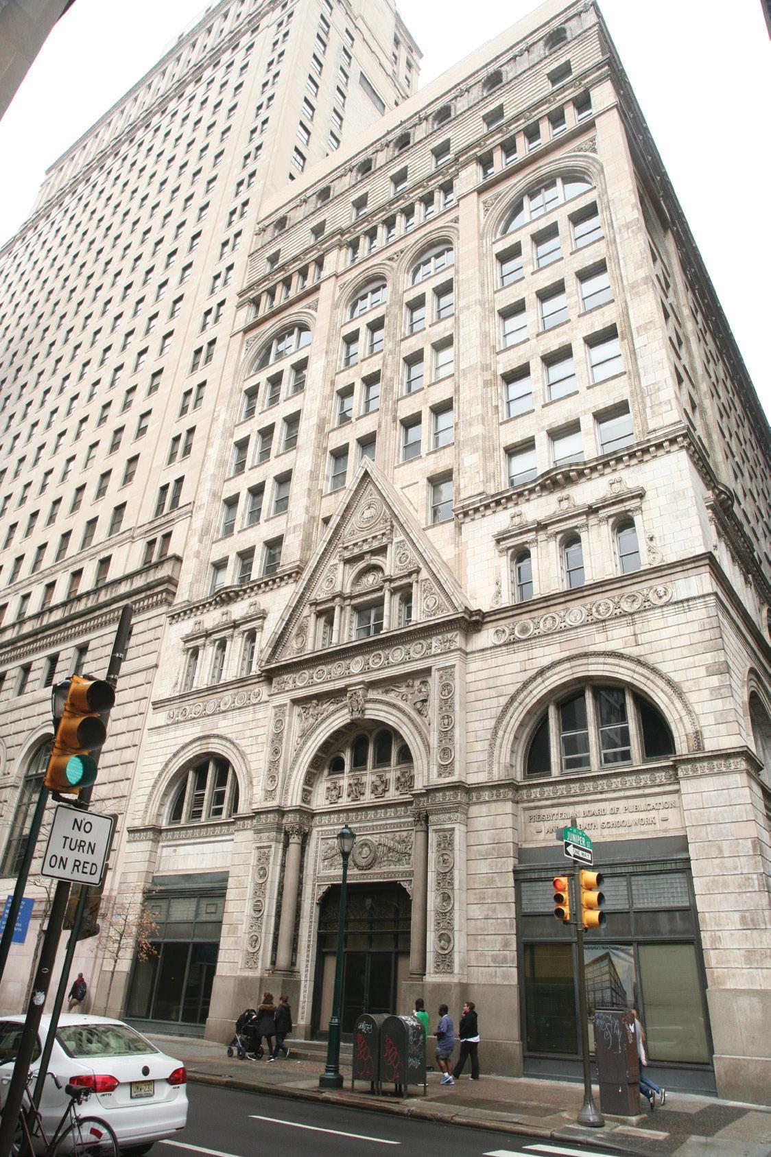
Figure 1. Witherspoon Building south elevation. Courtesy of JKRP Architects.
Original Structure Adaptive Reuse
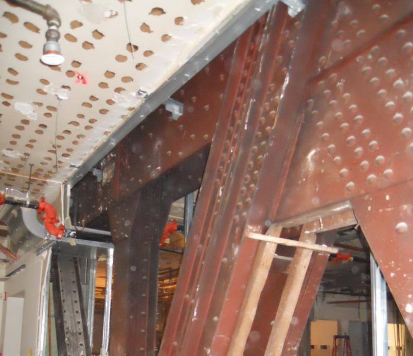
In general, the fl oors and main roof are constructed with 12-inch-deep, hollow clay tiles arranged in end-to-end, fl at arch construction with voussoir, or “keystone,” hollow clay tiles placed parallel to and on each side of the supporting 12-inch-deep Carnegie Steel B section “I” beams (Figure 2). e voids of the keystone tiles are also oriented parallel to the beam span and therefore perpendicular to the main arch tiles. is is referred to as a combined end and side confi guration. e beams are typically supported by built-up riveted steel plate and angle girders (Figure A, online) or steel B section girders. Built-up, story-high, riveted parallel top and bottom chord steel transfer trusses (Figure 3) support the south portion of the 4th and 5th fl oors and the columns that support the fl oor and roof framing above. Also, similarly constructed roof trusses clear span across the north end of the building above the 11th fl oor. In addition, except at the mechanical roof penthouse and standalone 1st fl oor shed, the main building columns consist of built-up riveted angle sections known as Gray columns (Figure 4, page 34 ). Portions of the basement fl oor framing over the sub-basement were constructed with brick arches spanning between steel beams. In contrast, the roof over the mechanical penthouse was constructed with 4-inch hollow clay “book” tiles that simple span between inverted tee or “bulb” steel purlins supported by steel B section beams (Figure 5, page 34). Round, hollow cast iron columns support the beams. ere is also an ornamental, cast-iron framed, single-story gabled roof structure that occupies what was originally an open courtyard area at the 1st or ground fl oor on the west side of the building. Details of notable original documented structural features
Historic of the building include: Gray Columns W It is interesting to note that fabricated columns in the Witherspoon Building appear B to have been used because the engineer and contractor had not transitioned from employing rolled steel “I” sections as
Part 1: Building History and Structure horizontal beam elements to vertical column elements, as
By D. Matthew Stuart, P.E., S.E., P.Eng, F.ASCE, F.SEI, A.NAFE, SECB is done today. e Gray columns used in the Witherspoon Building were a patented section that could be fabricated with structural shapes, in this case, angles that any steel mill could roll. Similar patented sections, like Phoenix columns, could not be fabricated with rolled sections. erefore, because Carnegie Steel supplied the beams for the building, it was assumed that the Gray column components were likewise rolled by Carnegie (cross-section (4) in Figure B, online).
In addition, it was confi rmed via fi eld measurements that the vertical angles used in the Gray columns conformed with the available standard angle sizes provided in the 1896 Carnegie Steel Pocket Companion. It is also interesting to note that both the Fisher Building in Chicago and Guaranty Building in Buff alo, constructed at the same time as the Witherspoon Building, used Gray columns. Main Roof Trusses
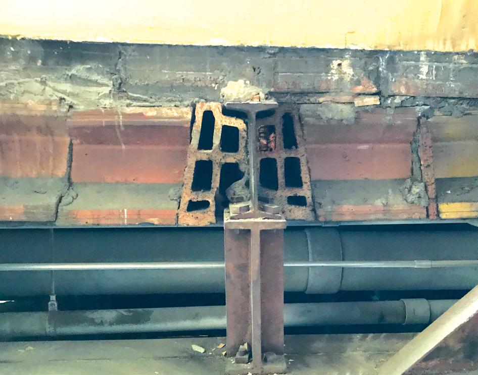
Figure 2. Voussoir keystone hollow clay tiles on each side of a typical Carnegie Steel beam. Figure 3. Riveted steel plate and angle transfer truss at the 4th fl oor.
At the north end of the building, to provide a column-free space at the 11th fl oor, 4-foot-deep Warren steel trusses, fabricated with angles, plates, and rivets, were constructed to clear span from the east to west sides of the building (Figure C, online). e trusses support the main roof framing, the original mechanical penthouse fl oor and roof framing, and the 11th-fl oor walk-on attic/ceiling in this same area of the building. 4th Floor Transfer Trusses
At a portion of the south end of the building, to provide a partial column-free space between the 2nd and 4th fl oors, story-high steel trusses, fabricated with angles, plates, and rivets, were constructed to span from east to west across the main rectangular footprint of the main building. e trusses support all fl oor and roof framing at and above the 4th fl oor in the area impacted by the same transfer members. e open area below the transfer trusses was initially used as a large assembly space called Witherspoon Hall. 11th Floor Ceiling
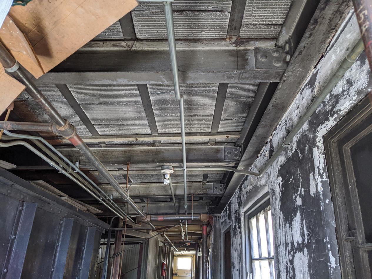
Because the story height from the 11th fl oor to the main roof structure is almost equivalent to a two-story space, steel beam framing was provided to support the 11th-fl oor plaster ceiling, which also served as an accessible attic/plenum space. is same ceiling framing extends over the entire building footprint and serves as the fl oor framing for the original mechanical penthouse. e attic/plenum is accessible from a spiral staircase adjacent to the passenger elevators that extends from the 11th fl oor to the main roof and a knee wall hatchway in the original mechanical penthouse. A portion of the attic/plenum was also originally accessible from the stair located in the northwest corner of the building.
continued on next page
ADVERTISEMENT–For Advertiser Information, visit STRUCTUREmag.org
ANCHORS & FASTENERS

DESIGN SOFTWARE INSTALLATION POWER TOOLS, DRILL BITS AND DUST EXTRACTORS ANCHORS


CCU+™ CRITICAL CONNECTION UNDERCUT (ICC-ESR 4810)
ANCHORS MADE IN THE
FOR MORE INFORMATION VISIT ANCHORS.DEWALT.COM


rooftop dunnage beams that span between the main building columns, except at the south end of the eastern beam, which is supported by the northernmost roof truss (Figure E, online). In addition, drawings provided by the Otis Elevator Company, dated 1950, indicate that the original two shafts at this elevator, shown on the Sanborn Map, were converted to a single shaft elevator as a part of the renovations. Northwest, Main, and South Stair Renovations
The extent of structural renovations that occurred at the top of the referenced stairs is unclear; however, the current configuration of the roofs of these stairs appears different from that shown on the Sanborn Map. In addition, it appears the southern stair may have been renovated as a part of the 2nd-floor mezzanine and 3rd-floor infill framing in the 1960s.
Figure 5. Book tiles supported by bulb tees spanning between Carnegie Steel beams at the penthouse roof.
Structural Additions
At some point during the life of the building, several structural renovations and additions were constructed. The exact age of these renovations is not known and include the following: 2nd Floor Mezzanine and 3rd Floor Infill Roof Top Dunnage
At some point during the life of the facility, steel dunnage frames were constructed above the south end of the main roof that are supported by steel wide flange columns that post down to the top of the original main building columns. There are two sets of dunnage frames that interface slightly. The southernmost dunnage frame supports an active prefabricated electrical room, while the northern dunnage frame supported mechanical cooling towers that were replaced as a part of the adaptive reuse project.
A mezzanine above the 2nd floor and infill framing at the 3rd floor were constructed between the 2nd and 4th floors at the south end of the building, within the same large assembly space originally called Witherspoon Hall. According to the National Register of Historic Places (NRHP) Inventory Nomination Form, this portion of the building may have been constructed in the early 1960s. The existing 2nd-floor mezzanine and 3rd-floor framing consist of a 2½-inch concrete slab on a 1½-inch cellular metal deck for a total of 4 inches. Historical information obtained from the Steel Deck Institute (SDI) indicates that the metal deck was a Q-Deck product manufactured by H.H. Robertson Company. The slab spans between W12 purlins and W14 girders. The 3rd-floor infill was reused for the latest adaptive reuse project; however, the 2nd-floor mezzanine was demolished to make room for a 2nd-floor loft that was subsequently not incorporated into the final project. Passenger Elevators Upgrade
According to the NRHP Inventory Nomination Form, the original passenger elevators were upgraded in the early 1960s. However, a comparison of the Sanborn Map for the original facility to the current building indicates that the only structural manifestation of this renovation appears to be the construction of a rooftop machine room penthouse located above the original elevator shafts (Figure D, online). Freight Elevator Upgrade Mechanical Penthouse
A one-story mechanical penthouse was constructed southwest of the passenger elevator penthouse sometime during the life of the facility. The space is accessed from the same spiral staircase described for the 11th-floor ceiling and provides the only access to the top of the main roof through the penthouse. The floor is framed with a solid, one-way 6-inch concrete slab supported by steel wide flange beams at an elevation slightly above the main roof level, which created a shallow crawl space that can be accessed via two floor hatches. The floor framing is supported by steel columns that extend down to the main building columns. The roof consists of precast concrete planks supported by open web steel joists that clear span to steel beam and column supports at the perimeter of the penthouse. A portion of the penthouse was also constructed above a large mechanical opening that was partially enclosed for the full height of the shaft with hollow, masonry pyro-bloc units that contain asbestos. This same shaft opening was infilled at each affected floor level as a part of the adaptive reuse.■ The author would like to thank Sara Wermiel, Ph.D. as the source for most of the historical information provided in Part 1.
Part 2 of this series will provide more details on the adaptive reuse and structural investigation.
Similar to the passenger elevators, it appears that the freight elevator was upgraded during the life of the building. The structural renovations included a new machine room penthouse supported by
D. Matthew Stuart is Senior Structural Engineer at Pennoni Associates Inc. in Philadelphia, PA. (mstuart@pennoni.com)


