7 minute read
Sulfur burning furnace optimization


Feature Sulfur burning furnace optimization
By: Timothy Connors, Senior Market Manager, Blasch Precision Ceramics
New products, technologies, and design tools are changing the way sulfuric acid plant furnaces are designed, operated, and maintained. Modern technologies are now combining experience with sophisticated design tools. The result is a holistic view of the furnace’s operation and the opportunity to craft highly customized designs, targeted at solving specific problems for owners and operators.
Capturing this opportunity requires analysing furnace designs with a combination of detailed sulfuric acid process knowledge as well as modern tools, like CFD modelling, to obtain an in-depth understanding of the challenges, the process environment, and the key variables that can be manipulated. Once an analysis is complete, technology providers must make critical design choices. In doing so, it is advantageous to have access to highly customizable and adaptable technologies to take full advantage of the analysis that was performed.
For example, it is useful to run a CFD model to identify improvement opportunities for a furnace with three baffle walls. However, if the analysis reveals the existence of “dead zones” in the furnace, the analysis is of very little value without the existence of a tool that can solve this problem. VectorWall™ Ceramic Furnace Internals are a highly customizable furnace technology capable of being configured to align its performance with both the needs of owners and operators and the results of a thorough analysis.
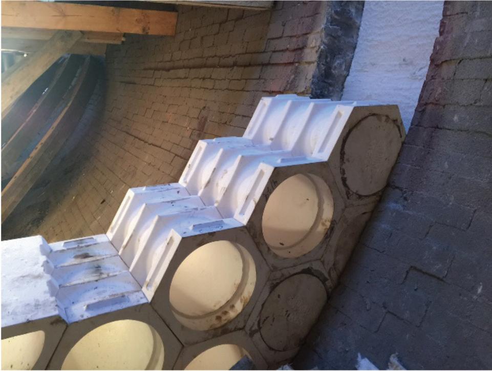
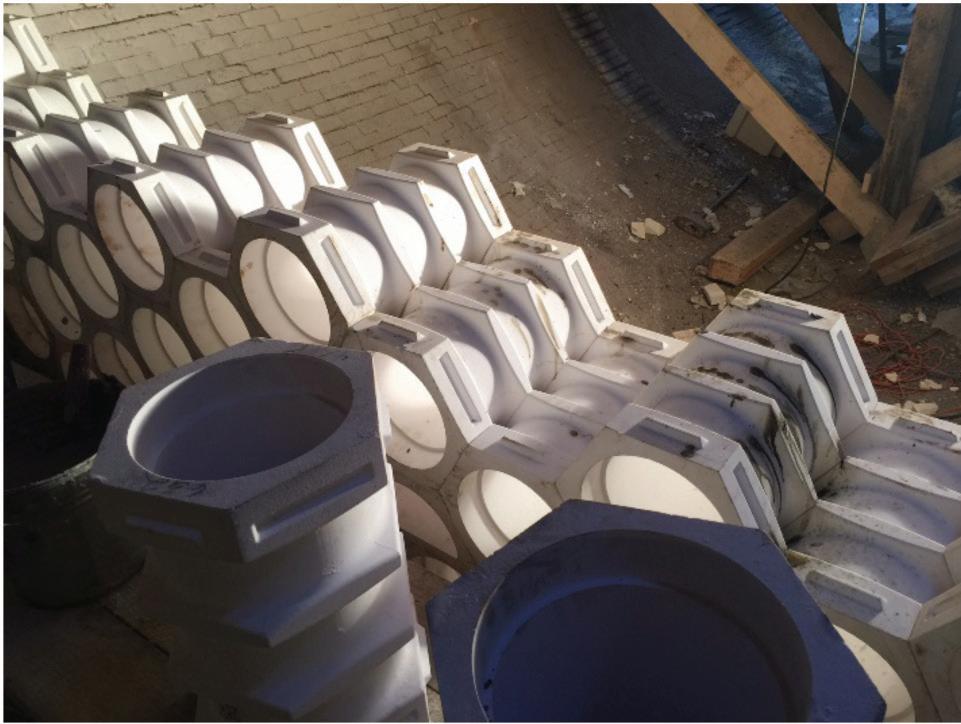
VectorWall™ Ceramic Furnace Internals are constructed from a series of hexagonal blocks that stack together without mortar and remain fully supported on all six surfaces, as shown in Fig. 1.
Each individual block can be fitted with a Vector Tile to create custom flow patterns inside the furnace, as shown in Fig. 1. Thus, flow fields can be manipulated using this technology to create the desired combustion environment and to ultimately help facility owners meet their various objectives.
Reduced pressure drop
CFD analysis shows that furnace pressure drops can be reduced by using a single VectorWall™ in place of a conventional baffle wall design while maintaining sufficient levels of mixing to allow for complete combustion.
Fig. 2 shows the typical pressure drop improvement associated with the VectorWall™ design, as compared to a furnace with a baffle wall design.
In 2015, a sulfuric acid plant owner sought a replacement for their existing furnace, and selected an MECS® furnace design, utilizing a single VectorWall™ in place of conventional baffle walls. In this particular case, the use of VectorWall™ Ceramic Furnace Internals proved to be even more advantageous than analysis indicated.
Increased capacity
A sulfur furnace can be thought of as a plug flow reactor. Such a reactor is designed for a certain target average residence time. Thus, if one can identify the total gas flowrate, the size of the furnace can then be selected to match the target average residence time. If done properly, the actual average residence time of the furnace will be equal to the target average residence time.
However, the average residence time is an average of the many different residence times that individual particles will have as they pass through the furnace. In a conventional baffle design, (Fig. 3), some particles will miss the baffles and have residence times that are less than the average; but other particles will hit the baffles and have residence times that are larger than the average.
In optimizing the performance of a furnace, it is useful to be able to analyse the distribution of these various residence times to see what portion of the particles in the furnace are exiting the furnace too quickly and what portion of the particles are in the furnace for longer than they need to be.
One other characteristic of the rotational flow is the fact that this tighter residence time distribution occurs overs a much longer path (contact pathway) than flows that go from Point A to Point B. This longer contact pathway does not add residence time, but it does add real estate to the transaction, and that ensures that complete combustion occurs prior to furnace exit. This not only improves the efficiency of the furnace, it protects the refractory downstream from combustion on the surface and resulting hot spots. These uncombusted particles are often referred to as “Fireflies,” and they are frequently seen exiting the furnace. That has not been the case in the VectorWall™ retrofits. All fireflies have been extinguished well before the furnace exit.
Fig. 4 compares the residence time distribution associated with a typical brick baffle design to the residence time distribution associated with a VectorWall™ design. Note that the narrower residence time distribution associated with VectorWall™ design causes an increase in the overall furnace efficiency.
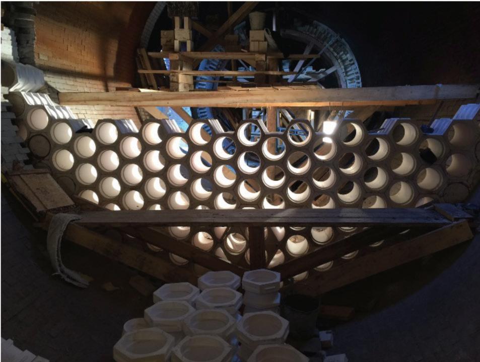
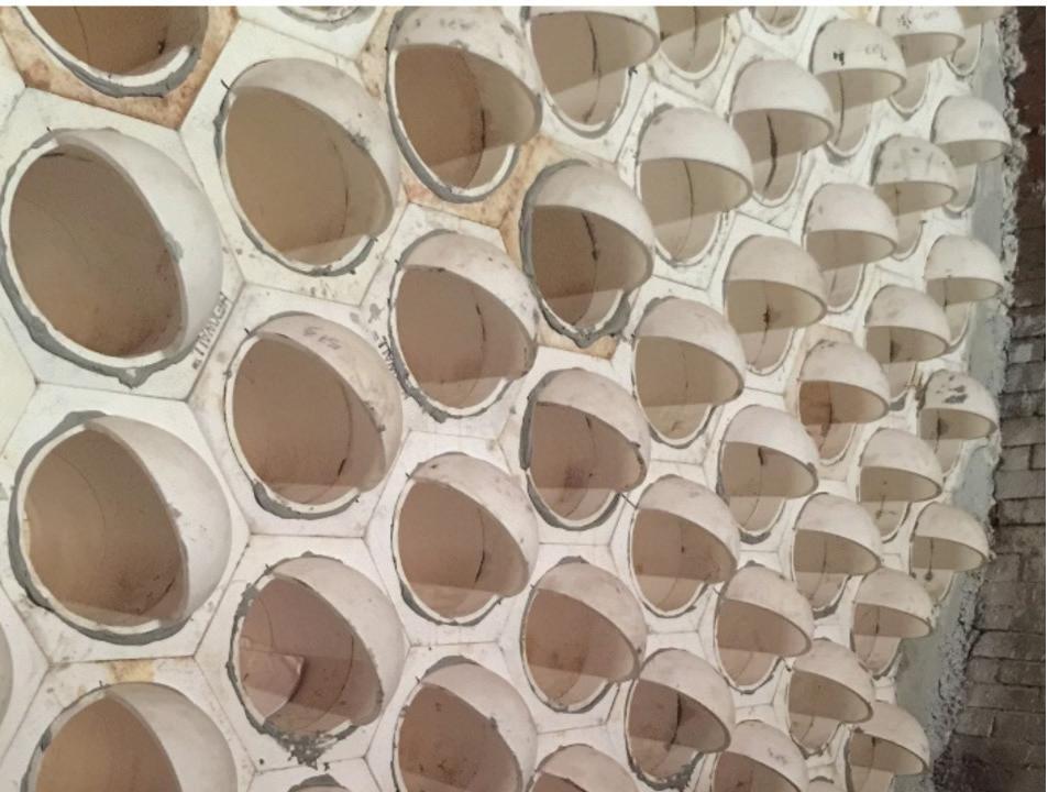
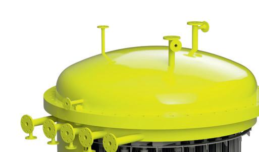
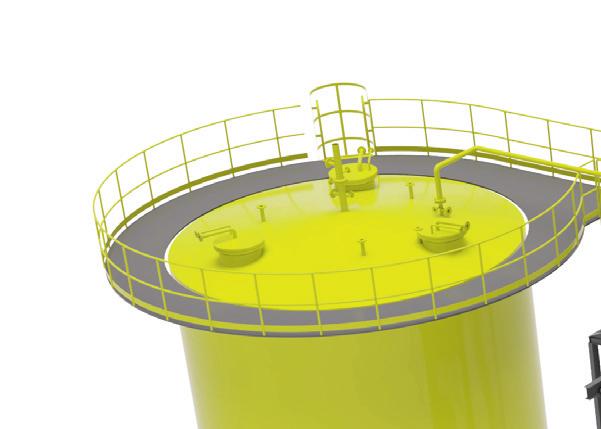
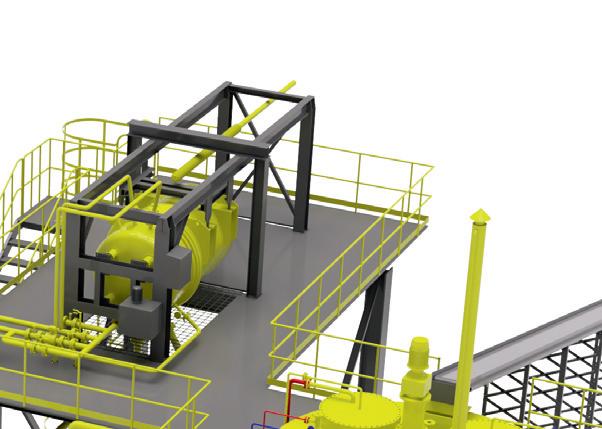
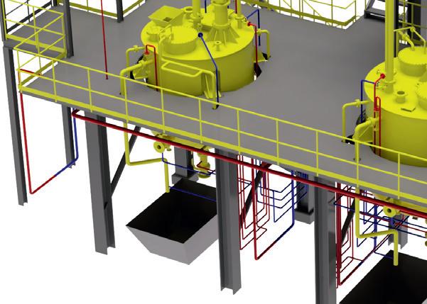
In one such case, in 2015, the owner of a sulfuric acid plant sought to replace a furnace with a larger furnace that would allow future capacity increases at the site. However, a larger furnace is more expensive, particularly for retrofits where plot space is limited and the window of time for installation is tight. In this case, a VectorWall™ design was used to narrow the residence time distribution and use the overall furnace volume more efficiently; the installation is currently in operation and is shown in the first photo in Fig. 5.
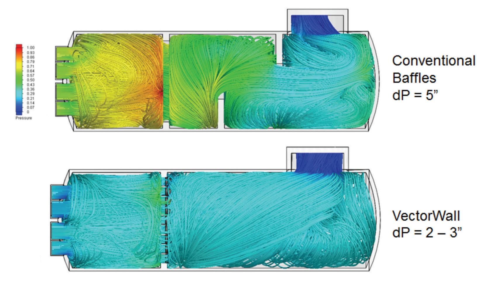

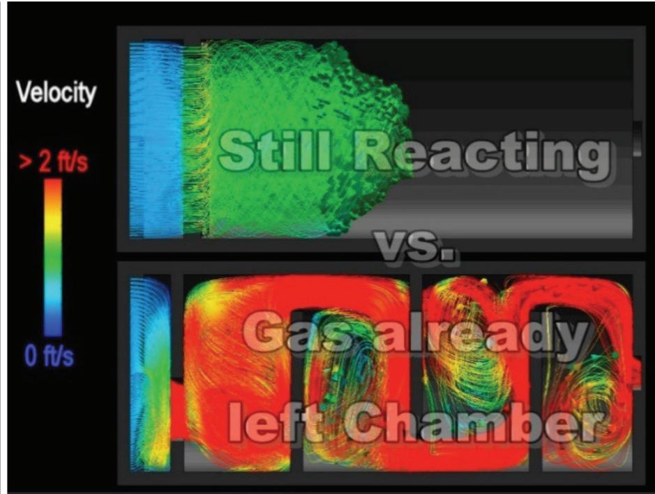
Fig. 3: Residence time distribution for 3 baffle walls vs. 1 VectorWall™
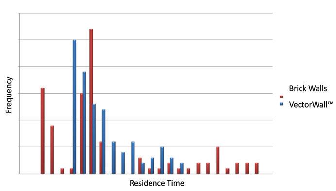
Fig. 4: Residence time distribution for 3 baffle walls vs. 1 VectorWall™
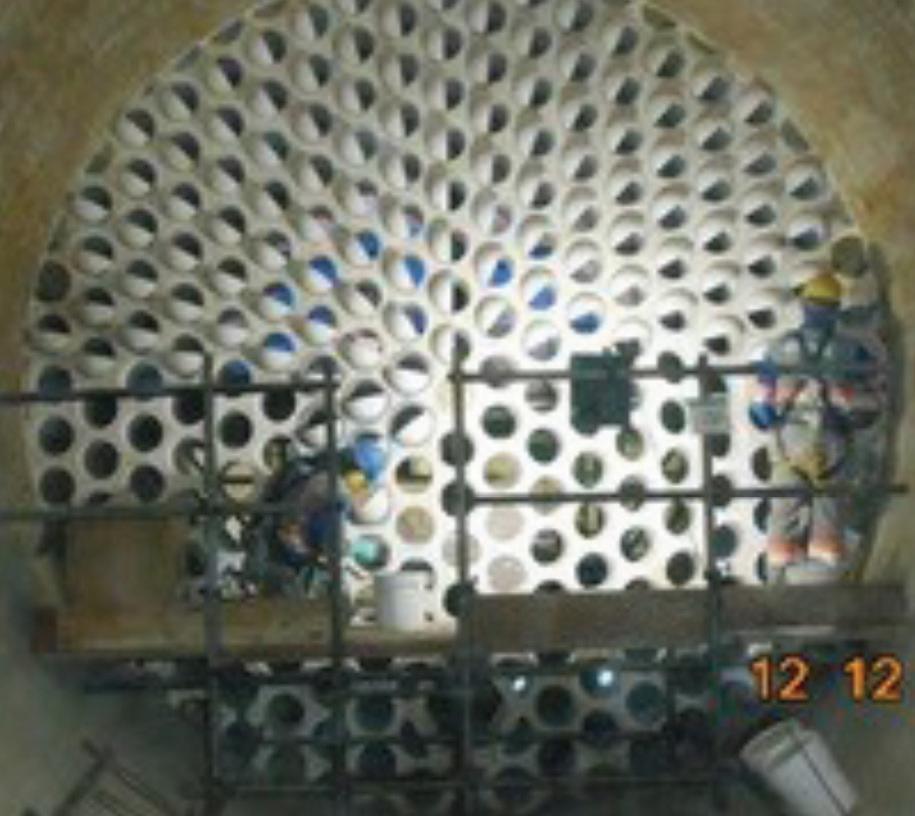
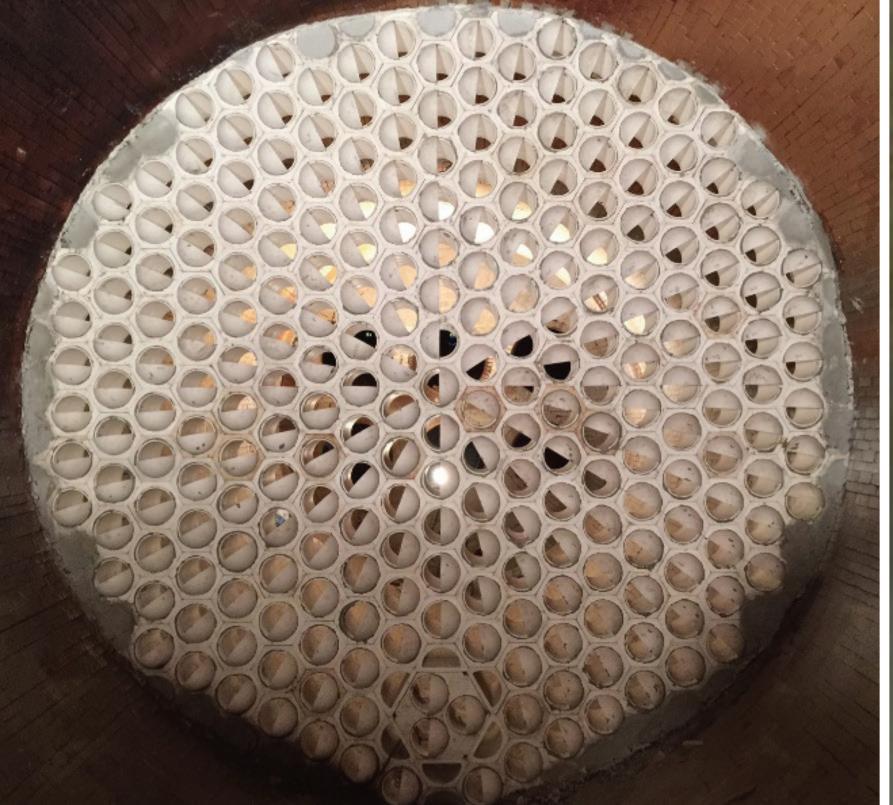
Fig. 5: Recent VectorWall™ installations for narrower residence time distribution.
Temperature differential/ control
One other effect that the VectorWall™ provides is resistance to radiant heat transfer. The Vector Tiles, while not restricting flow through the openings in the wall, do shade varying degrees of radiant line of sight. The standard Gen 1 tiles block 50% of the radiant heat, and Gen 3 blocks 100%, while not interfering with the flow through the blocks themselves.
As Fig. 6 shows, Zone 1 temperatures increased by about 100 degrees C, while temperatures on the backside of the VectorWall™ decreased by about 200 degrees C. This data is from a Claus furnace, but the exothermic nature of the combustion and the kinetic activity are similar for both, and in fact we’ve seen similar results – we just do not have data handy. On a related note, in staged combustion configurations in spent acid regeneration furnaces, we’ve seen decreases in NOx of up to 75% due to the much lower temperatures downstream of the wall, where air is being injected to create an oxidizing atmosphere.
Conclusion
The need for next generation furnace technology is great. It is driven by tightening budgets, environmental regulations, and tighter operating windows as well as broadening production aspirations, turnaround scopes, and technology availability. In this environment, unique process knowledge can be combined with cutting edge analysis tools and product technology in a way that meets the growing needs of owners and operators.
VectorWall™ Ceramic Furnace Internals can be used to meet a variety of challenges that many owners and operators face, including reducing pressure drop, debottlenecking, and capital and maintenance expense optimization.
Proper furnace design is not a trivial matter. However, owners and operators can
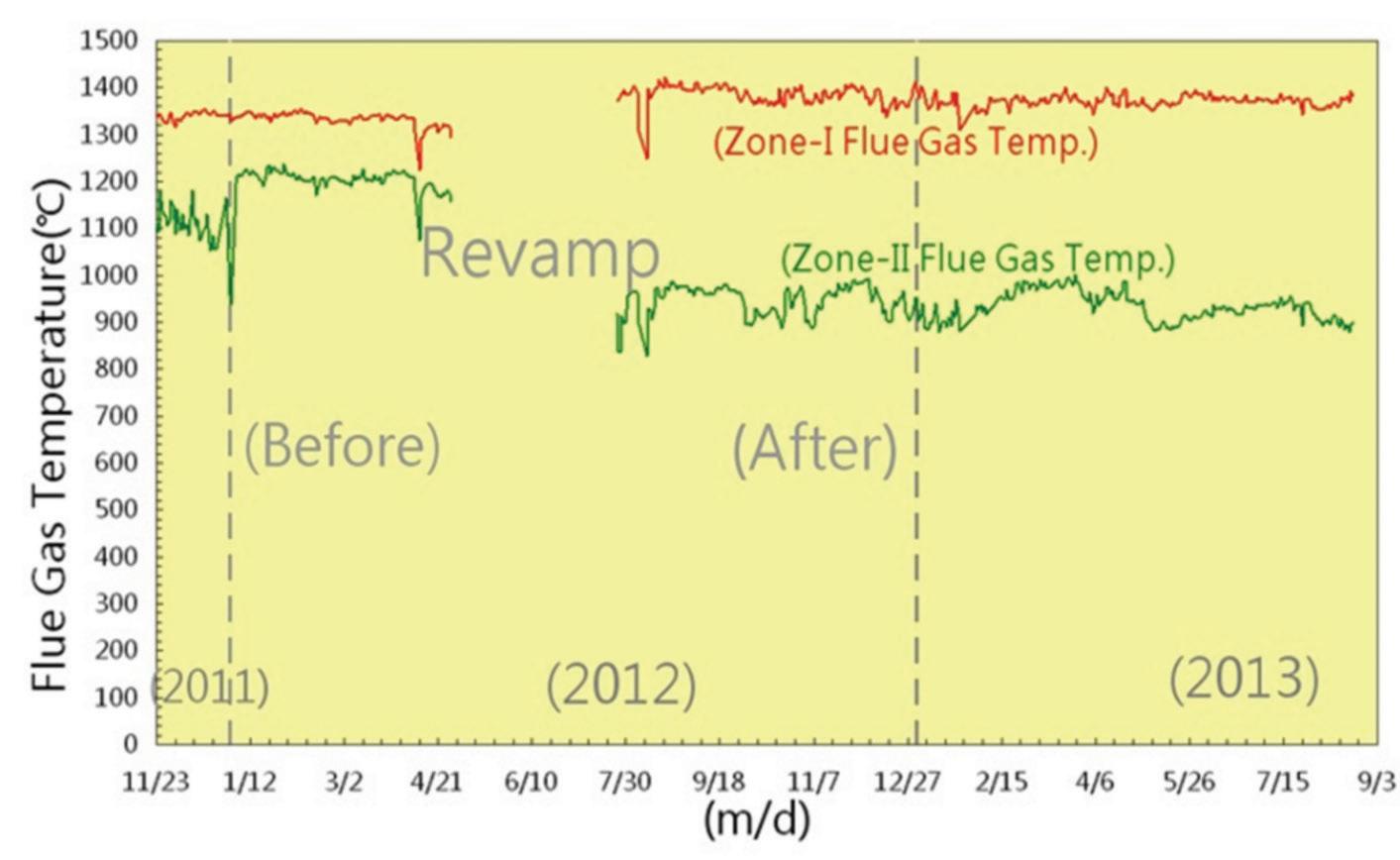
Fig. 6: Zone 1 vs. Zone 2 temperatures in a Claus furnace installation.
benefit from technology providers with deep knowledge of the process, command of cutting-edge analysis tools, and the ability to integrate analytical results with robust equipment designs. Thus, when analysed by the right industry experts, facility owners can realize improvements that meet and even exceed their goals.
For more information, please contact Timothy Connors at (518) 436-1263 ext 105 or tconnors@blaschceramics.com; or visit the company’s website www. blaschceramics.com. q
Plant Audit
Start-up & plant operation


Construction & commissioning Sulphurnet successfully installed the first fully automatic
Self Cleaning Liquid Sulphur Filter.

E&P Phase


