9 minute read
Lewis vertical sulfuric acid pumps save South american smelter $100K


lewis® vertical sulfuric acid pumps save South American
smelter $100k & 200 hours By: Martha Villasenor, Senior Sales Engineer, Weir Minerals
Leaks and failures
A smelter in South America was experiencing pump leakage and failure due to the extremely corrosive, high temperature acid in its sulfuric acid plant. The incumbent horizontal pumps leaked at the shaft seal and volute, causing excessive wear in the pumps’ components. This led to constant disruptions in the process, with failures occurring at least once a week.
Additionally, the leaks caused damage to the floor and hazardous working conditions for operators. The facility needed a reliable solution to keep their workers and the environment safe, and to increase uptime, since the plant was operating at only 50-70% of capacity due to the pump failures.
new pump design
The Weir Minerals team completed a full analysis of the sulfuric acid process and proposed a new layout incorporating Lewis® vertical externally mounted (form E) sulfuric acid pumps to replace the incumbent horizontal pumps.
By selecting a Lewis® externally mounted vertical pump design configuration, the facility would not need to build a separate pump tank, which would save on cost and space. Compared to a horizontal pump design, harsh acids do not touch the shaft sealing and won’t compromise the sealing elements in the vertical design of a Lewis® pump, eliminating the risk of acid leaks or spills on operators.
Additionally, Lewis® pumps are made from robust construction materials to combat the effects of a corrosive acid environment. Lewmet® nickel-chrome alloy is used for critical wearing parts to provide maximum corrosion resistance.
Lewis® vertical sulfuric acid pump
saving maintenance time and money
Now the pumps at the plant are no longer leaking or restricting plant capacity. After the layout changes were completed and the Lewis® pumps were installed, the pumps operated for more than 12 months without leaking or needing maintenance. Operators were extremely pleased by how long the pumps lasted and stopped for preventative maintenance after 12 months. Once restarting, the Lewis® pumps continued to operate for another 18 months without downtime. Compared to the incumbent horizontal pumps that lasted only one week, the operation saw a decrease in maintenance time by more than 200 hours per annum.
In addition to more reliable and safer operations, the plant no longer needed to
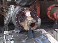
Leaks in the seal of the incumbent pumps.
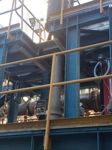
Lewis® vertical pump in operation.
make regular short-term replacements of the pumps’ impellers, volute, and seals, which resulted in a significant cost savings of more than $100,000 per annum.
For more information, please visit www.global.weir. q
ISO-FLOW™ Trough Distributors with SWIFT-LOCK™
Experience:
• Next generation Orifice distributor introduced in 2011 • Developed and patented by Chemetics
Features and Benefits:
• Orifice distribution provides consistent flow to each downcomer • Air gaps provide hydraulic separation and allow for easy troubleshooting • Calming plates promote even distribution - Integral screens catch chips to minimize plugging and allow easy cleaning - Internal channel minimises header pipes • SWIFT-LOCK™ system - Reduces distributor installation time by 50% - Simplifies tube bank installation/removal – time reduced by 90% - Eliminates 90% of nuts/bolts/washers • SARAMET® Construction for excellent acid corrosion resistance
The ISO-FLOW™ Trough Distributor is designed to be installed through tower manways and is ideal for retrofits.
Innovative solutions for your Sulfuric Acid Plant needs
Chemetics Inc.
(headquarters) Vancouver, British Columbia, Canada Tel: +1.604.734.1200 Fax: +1.604.734.0340 email: chemetics.info@worley.com
Chemetics Inc.
(fabrication facility) Pickering, Ontario, Canada Tel: +1.905.619.5200 Fax: +1.905.619.5345 email: chemetics.equipment@worley.com
By: Walter Weiss, Process Engineer, DuPont Clean Technologies, owner of MECS® sulfuric acid technology
In sulfuric acid production, over the years there has been (0.75 or 1 inch) ceramic material. much effort placed on improving catalyst performance in the The converter diameter and all the internals expand oxidation of SO2. This effort has resulted in new formula- with heat. A large converter can grow several inches raditions, new shapes and sizes, lower light off temperatures, ally from cold to operating temperature. The installation of and improved dirt handling capability. This effort has also the screen needs to accommodate this growth. Note that the seen modification in converter flow arrangements. In fact, screen may not grow directionally with the converter but may there are a few basic items that have remained relatively un- deflect some of its growth downward into the open area of the changed, except for the support of the catalyst. Overlooked steel supports below. Pressure drop likewise tends to deflect and taken for granted maybe, a refresher may be in order. the screen into these openings and not expand fully with the When overlooked long enough, problems may result. shell. Hence, screen sections are not installed with joints edge
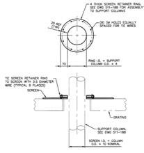
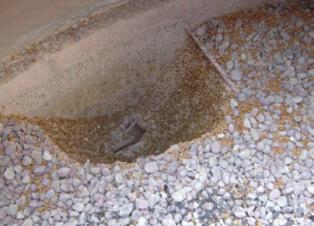
Catalyst is loaded into a multipass converter vessel to edge. An overlap of about 80 mm (3 inches) is suggested. with interbed cooling. A flow of gas bearing SO2 is directed The overlapped screen is tied with wire roughly 3.43 mm through the bed, normally in a downward direction. In the (1/8 inch) diameter made of the same material as the screen. design of the converter vessel, using stainless steel or car- Screen is trimmed to the shell diameter (cold) and the bon steel/cast iron, there is a support network that keeps the edges rest on a 90 mm (3.5 inch) wide retainer ring, which catalyst in its intended location. If this support network is is part of the converter shell. Some utilize the practice of a compromised or fails, catalyst can move from its intended slight roll of this screen edge up the shell wall. Posts in the sion plate or converter floor below. This leaves a thin spot in location to other locations within or even outside the con- converter must pass through the screen and catalyst bed. The the catalyst bed. See Fig. 4. verter. Needless to say, catalyst not in the location neces- screen needs to be cut to fit around these posts. A retainer ring Thin spots allow a low resistance path for gas circumsary to properly contact the gas flow is not effective in the inside radius is 5 mm larger than the post and is installed to venting the catalyst bed with a reduction in overall bed conversion of SO2 to SO3. slide down the post and cover the screen. Retainer ring an- pressure drop, temperature rise, and conversion. The cata-
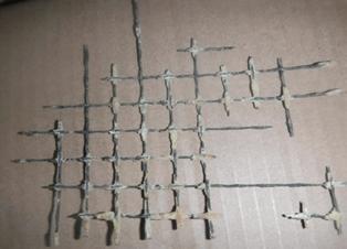
In current designs, the converter fabrication often uti- nulus is 70 mm (2.75 inch) wide radially. It is then wired into lyst may remain directly below the opening in the support lizes a welded grid of stainless steel members supported by place using the same wire as the screen joints. See Fig. 2. screen but may be carried downstream and into the outlet posts or by direct attachment to vessel or core walls. Older The life of pass one screen and wire is typically eight to duct and heat exchangers. designs utilized a piecemeal arrangement of triangular cast There is no on-line repair solution for the operator. There iron grids supported by cast iron posts. On top of either sys- is no good short shutdown solution either. If loss of throughtem was a screen and the bed was loaded on the screen. put or high stack emissions resulting from the support failure
A typical catalyst bed loading is depicted in Fig. 1, with make further operation intolerable, then the plant needs to the catalyst layered between two 50 mm (2 inch) courses of be shut down, the converter needs to be cooled, and the bed ceramic such as support balls or special river rock. The upper contents removed to access the screen. level of ceramics serves to stabilize the top of the bed against the horizontal movement from gas flow as well as provide some preliminary distribution of dust and ash entering the bed with the gas.
The lower level of ceramic support separates the catalyst from the screen. It is important to completely cover the screen with ceramics as contact between the catalyst and stainless steel material may cause damage to both. During catalyst screening, the support material is also removed from the bed to allow inspection and cleaning of the screen. The ceramics are replaced upon completion, but some loss ten years when operated at 600°C (1100°F) or more. Screens of material is common. More screenings result in more in the other beds last longer–often much longer–and are not material loss. There is rarely an effort made to replace this changed out for many years. missing material and the thickness of the ceramic bed de- The screen should be inspected and cleaned whenever clines over time. This allows contact between the catalyst the catalyst bed is screened. Many owners change this mateand the screen. In addition to increased screen corrosion, rial out proactively based on time or visual appearance. Even catalyst rings may fall through the damaged screen. without screening, the condition of the screen may be ob-
Screen mate- served from the vestibule below. Sometimes, the screen is rial recommended left in service too long and failure results, as shown in Fig. 3. for the higher oper- Failed screen material allows the support media and ating temperatures then the catalyst rings to pass through and fall to the diviof passes one and two is 321 stainless steel. The other passes operating at lower temperatures can utilize 304 stainless steel. Although some owners prefer to use 321 stainless screen material throughout to Fig. 1: Typical catalyst bed loading simplify inventory. elevation.
Screen diameter is normally 3.76 mm (0.148 inch) with centerline spacing of 13 mm (0.51 inch). This should give an open area of 50 percent or more. This is sufficient to support the 19 or 25 mm
Fig. 2: Retainer rings help seal space around converter posts. Fig. 4: Thinning catalyst bed section due to failed support.
About DuPont Clean Technologies
The Clean Technologies division of DuPont is a global leader in process technology licensing & engineering, with an unwavering commitment to customer support. We provide extensive global expertise across our portfolio of offerings in key applications - MECS® sulfuric acid production, STRATCO® alkylation, BELCO® wet scrubbing and IsoTherming® hydroprocessing. Offering critical process equipment, products, technology and services, we enable an array of industrial markets, including phosphate fertilizer, non-ferrous metals, oil refining, petrochemicals and chemicals, to minimize their environmental impact and optimize productivity. We are dedicated to helping our customers produce high-quality products used in everyday life in the safest, most environmentally-sound way possible, with a vision to make the world a better place by creating clean alternatives to traditional industrial processes. We make everyday life better, safer, cleaner. For more information, please visit www.cleantechnologies.dupont.com
About DuPont
DuPont (NYSE: DD) is a global innovation leader with technology-based materials, ingredients and solutions that help transform industries and everyday life. Our employees apply diverse science and expertise to help customers advance their best ideas and deliver essential innovations in key markets including electronics, transportation, construction, water, health and wellness, food and worker safety. More information about the company, its businesses and solutions can be found at http://www.dupont.com. Investors can access information included on the Investor Relations section of the website at investors.dupont.com.
DuPont™, the DuPont Oval Logo, and all trademarks and service marks denoted with ™, SM or ® are owned by affiliates of DuPont de Nemours, Inc. unless otherwise noted. q


