Rev. 04.2022
I www.swisspearl.com
DIM Design & Installation Manual Swisspearl Largo Gravial
Swisspearl

General information, Program Design Installation
Panel sizes
Adhesive Sigma 8 Accessories General remarks
Remarks, system, validity, ordering material, rain screen cladding 3 Overview panel, sizes Application cutting 4-5
Ordering material, Software support, Positioning, Cutting from CAD 6 Adhesive application 6
Gravial Sigma 8 7 Fasteners 8 Joint material 9 Terminology 10
Corner zone, Application, Windload 11 Insulation, Rear ventilation, Open joints 11 Ventilation openings, building dilatation 11 Panel support, Compatibility, Sub-frame 12-13 Reference Lines 14
Metal panel support Details Swisspearl Gravial Timber panel supports
Distances to panel edge, joints, fixed and sliding points 15 Aluminum, steel sub-frame 16-19
Drilling and riveting, fixed point, sliding point, fastener distances 20 Windload guidelines 21-22
Single span panel 23
Swisspearl Largo Gravial portrait/landscape 24-26
Outer corner, Inner corner, Window jamb, window sill 27-29 Window head, bottom detail, coping detail 30-32 Distances to panel edge, panel joints 33 Timber quality, screws, ventilation cavity 33 Fastening on timber battens, 34-36 Horizontal section, vertical joints at windows, fastener distances 37-38
Windload guidelines 39-40
Single span panels, Installation 41
Swisspearl Gravial Details
Storage on site Cutting, Tools Cleaning
Swisspearl Largo Gravial portrait/landscape 42
Outer corner, Inner corner, Window jamb, window sill 43-45 Window head, bottom detail, coping detail 46-48
On site storage, Guideline, Stacking 49 Fabrication, Cut outs, Sealer, tools 50 Cleaning procedures, Masking tape 51
This DIM (Design + Installation Manual) provides technical information regarding design and installation. Refer to area manager and local distributor for further information such as:
• Terms of delivery
• Pricing
• Products and colors
• Lead time, etc.
More general information available on www.swisspearl.com
CH- 8867 Niederurnen Tel. +41 55 617 11 60 Email: info@swisspearl.com
Please consult your local distributor and or the Technical Advisor prior to the commencement of shop drawings or installation for the most current DIM guide. The current DIM can always be found at www.swisspearl.com. All previous DIM guides should be disregarded and are no longer valid Product warranty 20 year warranty for the functional quality of panels and accessories, provided that the installation is in full compliance with this DIM.
Maritime conditions call the use for stainless steel rivets. Those may be used on steel or anodized aluminum sub frame. Maritime conditions are considered 50m to 1km (0.03 to 0.6 miles) from the sea. Material specification for sub frame, fasteners and accessories to cater for maritime conditions according to local standards.
• Maximum protection against weather
• Excellent longevity
• Easy installation in any climate
• Almost no maintenance required
• Proven details
• No cracks, paint or sealant problems
• High sustainability
• Non combustible
Subtle visual differences may occur between product batches. Therefore we recommend ordering by job or specific elevation if ordering in phases.
The information and recommendations contained in this Design & Installation Manual ("DIM") are offered as a service to architects, constructors, installer and other persons involved with our products and are not intended to relieve them from their own responsibility. The information and recommendations provided herein are believed by Eternit (Schweiz) AG ("Eternit") to be accurate at the time of preparation of this DIM, or obtained from sources believed to be generally reliable. Eternit makes no warranty concerning the accuracy of the content of this DIM and shall not be liable for claims relating to any use regardless of whether it is claimed that the information or recommendations are inaccurate, incomplete, or otherwise misleading. The information and recommendations herein are intended to be used with the judgment and experience of professional personnel competent to evaluate the significance and limitations of the material contained. Eternit expressly disclaims any guarantees or warranties, expressed or implied, for anything described or illustrated herein and assumes no responsibility or liability for damages of any kind, including - without limitation - bodily harm, injury or damage to property inferred from this DIM or the use of the materials described herein.
• Density > 1.8g/cm3
• Modulus of elasticity ca. 15'000 MPa
Type L (portrait)
Type Q (landscape)
• Characteristic value for bending strength (average) ca. 22.4 MPa
• Thermal expansion coefficient 0.01 mm / m / °K
• Fire classification according to NFPA 285 EN 13 501-1 & A2-s1, d0
• Frostresistance and durabitliy under EN 12467
• Thermal range - 40°C to + 80°C
Overview of colors and panels available see: «Swisspearl Design Solutions, products and system».
Further design router variants on request. 1 Portrait Panel Type L
Landscape Panel Type Q
The type must be specified when ordering whole panels. (cut to size on site)
Gravial 9/12 mm thick panels - max. net panel sizes
Swisspearl Largo Gravial Nobilis Carat
Swisspearl Largo panels can be attached to vertical timber or metal profiles. Suitable for new facades or existing cladding renovations.
All panel edges cut on site or at fabricators workshop must be sealed by LUKO sealer, provided by Swisspearl.
Thichness mm 9/12
Weight ca. kg/m² 24.1
Format
Untrimmed panels
max. net panel sizes Landscape (Type Q) Portrait (Type L)
3070 × 1270 3038 × 1250 1250 × 3050
2530 × 1270 2508 × 1250 1250 × 2510
Untrimmed panels will only be provided to approved fabricators. Untrimmed Swisspearl Largo panels must be trimmed 10 mm on all four sides. Only trimmed Gravial facade panels are delivered.
Signage, light fittings, etc. Provide structural attachment points behind the panel as required. Leave generally min. 6 mm (¼”) free gap between panel edge and installation - so as not to constraint the panel movement.
Supplementary panels are from the standard Carat and Nobilis range available.
Specially ordered ARSB panels are signified by printed squares on the backside of the panel. Please consult with your adhesive manufacture prior to installation. Zenor panels only available for face fastened system.
Glue manufacturer's instructions for use must be strictly followed regarding all aspects, including:
• Cleanliness of panels and support profiles
• Panel and air temperature
• Air moisture content
• Etc.
• For exterior application the panels may be glued to aluminium supports only.
• Sub framing to be approved by glue manufacturer prior to stating the installation.
Panels ordered for adhesive application are called ARSB and are available upon request at time of order. Standard Swisspearl panels cannot be used for adhesive application.
Warranty Panel manufacturer provides functional warranty for the panels only. Warranty for the attachment of the panels to be obtained by glue manufacturer.
Large format Largo Gravial fiber cement facade panels, with a concealed system, consists of a high quality design, which represent the pure principle of a ventilated facade without any visible attachments.
The sophisticated system concept of the pnael clip allows Sigma
8 Pro to be mounted on standard spacer screw, wood-metal, metal and thermal bridge optimized substructures.
The Sigma 8 Pro system consists of 9/12 mm thick Largo Gravial panels with a maximum size of 3050 × 1250 mm; with undercut anchors on the rear side and attachment cleats that are fastened to vertical sub frame profiles made out of timber battens or metal profiles out of aluminium or galvanised steel. The drilling of the undercut holes requires high precision and must be carried out at the factory in Niederurnen, Switzerland. All attachment cleats are installed on site. The panels are cut to size and packed onto pallets at the factory according to dimensions provided by the customer.
1 Swisspearl Largo Gravial panel 9/12 mm
2 Omega cleat S8Pro
3 Panel clip S8Pro
4 U-Cleat S8Pro
5 Screw SR2 Inox, 4,8×30 mm, black powder coated
6 Threaded anchor S8Pro
7 Spacer S8P
8 Hexagon nut with flange and locking teeth
9 Migration protection-K S8, Stainless steel bright
More details about the system, see Design and Installation Manual Sigma 8 Pro.
1 Screw, inox, saucer head Ø 12 mm, T20 drive, blank or powder coated
4.8 × 30, 4.8 × 38 mm
4.8 × 44, 4.8 × 60 mm
2 Torx bit T 20 W
3 Aluminium rivet head Ø 15 mm, blank or powder coated
• 4.0 × 18-K15, 8-13 mm grip range
• 4.0 × 24-K15, 13-18 mm grip range
• 4.0 × 30-K15, 18-23 mm grip range
4 Fixed point sleeve aluminum type 8
5 Stainless steel rivet, head Ø 15 mm, blank or powder coated
• 4.0 × 18-K15, 9-14 mm grip range
• 4.0 × 23-K15, 14-19 mm grip range
6 Fixed point sleeve stainless steel type 8
Maritime conditions call the use for stainless steel rivets. Those may be used on steel or anodized aluminum sub frame. Maritime conditions are considered within a distance of 1 km (0.6 miles) from the sea. Material specification for sub frame, fasteners and accessories to cater for maritime conditions according to local standards.
1 EPDM band, black, 60 mm wide for intermediate supports with side lips, in 50 m rolls
2 EPDM band, black, 100 & 120 mm wide for butt joints with side lips, in 50 m rolls
3 EPDM band, black, 150 mm wide for inner and outer corners with side lips, in 25 m rolls
4 Ventilation profile, raw aluminum or standard colors, 50 × 30 mm, 70 × 30 mm, 100 × 40 mm. 2500 mm long, 0.6 mm thick
5 L-flashing, stainless steel, millor powder coated, 0.5 mm thick 2510 / 3050 mm long
6 Horizontal joint flashing, aluminium, powder coated black, 0.5 mm thick 2510 / 3050 mm long
The design principle involves the deflection (screening) of the rain water. As the panel joints are not sealed, minimal amounts of water can gain access into the air cavity behind the panel. The cavity is naturally ventilated by vent gaps at bottom and top, so that any moisture will evaporate naturally by thermal action.
Cavity behind panel with ventilation gaps at bottom and top.
Thermal insulation layer (4)
To increase the thermal insulation capacity of the exterior wall.
Substrate (5)
Face of exterior wall, such as plaster, concrete, exterior sheating, wind proofing layer, etc.
Cladding (1)
Panels with open or closed joints, in one plane or lapped.
To support the cladding dead and wind load generally vertical panel supports in timber or metal.
Exterior wall (6)
Brick, concrete, wood and steel studs
Corner zone
Corner zone Corner zone
Typical wall zone
Swisspearl cladding panels can be attached to vertical supports made of timber, aluminium or steel.
Min. manufacturer cavity depth:
Mandatory for issuance of the warranty letter.
Cladding height min. cavity
< 6 m 20 mm 6 - 30 m 30 mm > 30 m 40 mm
Always consider local standards when determining windloads and related panel fasterner distances. This is especially important for tall buildings, for buildings with special shapes and for high wind exposure areas.
Building tolerances must be allowed for. The cavity may not be reduced by horizontal profiles or any stray objects such as loose insulation and other materials.
Minimum airflow at the backside of the panels should be 100% free of obstructions with no less than 200 cm 2 of vertical airflow (Min 20 mm System depth) behind panels. Minimum air flow at base and top of walls is required to have at least 60% unobstructed ventilation if using ventilated profiles.
Ventilation cavity with perforated horizontal subframe components
Min ventilation gap to be 40 mm. Horizontal profiles should allow min. 75% airflow. In advance please contact your Technical Service for approval.
The buildings structural expansion joints should be considered when designing subframe systems. Structural expansion joints must be applied to sub frame and cladding as provided to the building structure.
Swisspearl Largo Gravial
Panel must be supported on an even surface. If perforated angles are placed between the panel and batten/vertical profile the closure piece must not exceed 0.8 mm. Perforated angles have to allow ventilation entrance with a min. perforation of 60%. The use of an aluminium mesh is possible. It has a high ventilation ratio, thin material thickness (no push out of panel) and is easy to install.
Untreated aluminum material such as Window sills, frames, etc. is not compatible with cement and must be protected against dust from drilling panels, etc. Aluminum components are to be used in anodized or powder-coated or Kynar Coated for exterior applications with protective films.
Generally to keep the cladding maintenance free the use of sealants should be avoided. Where the use of sealant is unavoidable Polyurethane, Acrylic or Hybrid Polymer products would be best suitable. Before applying any sealant to fiber cement material the compatibility must be checked as certain materials leave permanent staining on panel surface. 1 Swisspearl Largo Gravial 9/12 mm
Reference lines
Min. panel width
Portrait installation
The planning of vertical joints can be done with a maximum panel usable dimension. Aesthetically the building corners or certain reference lines can be divided. The lintels should be considered as horizontal reference lines.
Landscape installation
The minimum panel width for portrait Gravial panels is ≥300 mm. In case of continuous vertical stripes, control that the Gravial lines are even. The height of the landscape Gravial panel is ≥300 mm.
Min. width portrait Min. width landscape
Should you consider a smaller width, please get in touch with your Swisspearl Technical Advisor.
For fastener distances on Gravial panels ≥300 mm, see Largo large size format documentation.
Swisspearl rivet
Each panel must be fastened by 2 fixed points in the panels center to support the panels deadload. All other rivets are sliding points.
Sub-frame engineering Engineer / contractor is responsible for the design and installation of all sub frame parts including all pertaining fasteners.
80
8
80
Use centering drill gauge so the holes will be concentric to the Ø 9.5 mm hole in the panel. Use drill bit type A for aluminum profiles and type S for steel.
29 8 29
Swisspearl rivet Ø 15 mm 4.0×18-K15
Diameter 9.5 mm
Horizontally 29 mm
Vertically 80 mm
Minimum edge distances
Horizontally 29 mm
Vertically 60 mm
Panel edge distances
Horizontally and vertically 100 mm
Typical panel joint is 8 mm, this allows panel scraps to be used as spacers. Wider joints will make any inaccuracies in the installation less noticeable.
The sliding point connection is NOT meant to accomodate building drift or seismic movement.
T-Profile 120 mm Continuous Gravialgrid
T-Profile 140 mm Individual Gravial grid
Intermediate support L-profile 45 mm Continuous Gravial grid
T-profile 120 mm and L-profile 45 mm Individual Gravial grid
1 Swisspearl Largo Gravial 9/12 mm 2 Vertical profile T-profile 120 mm 3 Intermediate profile, L-profile 45 mm 4 Vertical profile, T-profile 140 mm 5 Rivets 4.0 × 18-K15
Jobsite fabrication
Detail engraving Gravial grid
The arrangement of the sub-frame will always depends on the grid of the engraving.
Panel width minus lateral edge distance due to raster engraving = number of millings
Even = X Uneven = A; B
Onsite Gravial fabrication
When Gravial planels are cut on site, please note that minimum edge distance of 4 mm remains.
All cut edges must be afterwards treated with Luko sealant.
Aluminum thickness should be a min. of 2 mm. Profiles should not exceed 3 m and profile breaks should coincide with panel joints.
4.0 × 18 - K15 rivet, head Ø 15 mm, powder coated or blank, grip range 8 - 13 mm.
Use two vertical profiles to vertical panel joint so that each can be broken on its horizontal panel joint leven.
Steel panel supports to be min. gauge 18 (1.27 mm / 0.05”) to obtain nominal pull out value. Profiles should not be longer than 6 m (20’).
Stainless steel rivet
4.0 × 18 - K15 rivet, head Ø 15 mm, powder coated or blank, grip range 9 - 14 mm.
Engineer / contractor is responsible for the design and installation of all sub frame parts including all pertaining fasteners.
Panel joints read as shadow lines. It is recommended to blacken the metal where visible, with paint or PVC paint tape.
1 Swisspearl Largo Gravial 9/12 mm
2 Rivet
3 Panel support profile
4 Joint flashing (optional). L = panel width - 2 mm.
5 Thermal insulation
Any breaks to panel support profiles must be located at panel joints as shown. Flashing cut at one vertical as shown to prevent lateral dislocation of flashing.
Use rivet gun GESIPA ACCUBIRD or similar. Do not use pneumatic equipment. Use centering drill gauge with drill bit Ø 4.1 mm to obtain concentric hole [A/3].
Fixed point for Aluminum, Type 8 Ø 9.4 mm [B/4]
• Rivet head Ø 15 mm 4.0 × 18-K15, blank or powder coated, grip range 8-13 mm
Fixed point steel A2, Type 8, Ø 9.4 mm [B/4]
• SS Rivet, head Ø 15 mm, 4.0 × 18K15, blank or powder coated, grip range 9-14 mm
Use centering drill gauge with drill bit Ø 4.1 mm to obtain concentric hole [C/5]
• Alu Rivet, head Ø 15 mm 4.0 × 18K15, blank or powder coated, grip range 8-13 mm. Sliding points for Steel Sub-frame use concenter drill gauge with drill bit Ø 4.1 mm to obtain concentric hole [C/5]
• Sliding points for Steel Subframe. Use centering drill gauge with drill bit Ø 4.1 mm to obtain concentric hole [C/5]
• SS Rivet, head Ø 15 mm, 4.0 × 18K15, blank or powder coated, grip range 9-14 mm
Each panel must be fastened by 2 fixed fastening points in the panel center, installed first. All the others are sliding points.
1 Support profile 2 Swisspearl Largo 8 mm 3 Concenter drill gauge 4 Fixed point sleeve, type 8 5 Rivet 4.0 × 18 - K15
Fixed point
Sliding point
Metal sub frame - Gravial 9/12 mm façade panels - rivet distances
Characteristic value Design value Recommendation for maximal spacing d (distance between rivets or screws) of wind suction of wind suction (according to European (including a chosen Vertical panel (portrait) Horizontal panel (landscape) standards) safety coefficient of 1.5) horizontally vertically horizontally vertically kN/m2 psf kN/m2 psf mm mm mm mm
- 0.70 - 13.90 - 1.0 - 20.9 600 725 725 530 - 1.00 - 20.90 - 1.5 - 31.3 600 590 675 530 - 1.30 - 26.50 - 1.9 - 39.7 600 490 520 530 - 1.80 - 37.60 - 2.7 - 56.4 400 490 430 370 - 2.30 - 48.70 - 3.5 - 73.1 400 420 400 370 - 2.70 - 55.70 - 4.0 - 83.5 400 330 370 370 - 3.30 - 69.60 - 5.0 - 104.4 300 370 370 280 - 4.00 - 83.50 - 6.0 - 125.3 300 330 330 220
Above table is a guide line for 2 or more fasteners in vertical and horizontal direction. The spacings originate from 1230 × 3050 mm full size panels with equal distances between rivets. Data may be interpolated.
Metal sub frame - Gravial 9/12 mm façade panels - rivet distances
The spacings in above table are provided as indication. For the actual cladding design a locally licensed engineer shall assume responsibility for calculation and verification.
Panel data
n Modulus of elasticity MOE ca. 15’000 MPa n Characteristic value of bending strength (average: lengthwise / crosswise) or MOR (average) 22,4 MPa n Density > 1.8g/cm3
values Resistance of aluminum and steel rivets 4.0 × 18 K15
600 mm
Middle 2100 N Edge 1350 N Corner 1050 N
The data was evaluated according to ETAG 034 using 9/12 mm Gravial panel, and includes no safety factor. Diameter of panel hole must be 9.5 mm, and rivet head must be 15 mm. Min. thickness for steel profiles to be 1.27 mm, and 2 mm for aluminum. Edge distances 29 mm horizontally, 80 mm vertically. The data may be interpolated.
Fixed point Ø 9.5 mm [F] Sliding point Ø 9.5 mm
Fastener distances for soffit panels and suspended ceilings not to exceed 500 mm.
Fixed point Ø 9.5 mm [F] Sliding point Ø 9.5 mm
Max. distance between fasteners for single span panels 570 mm, unless smaller distances is required by high wind load as per table of fastener distances.
If more than 5 single span panels are ad- joining each other - the chain of fixed points must be interrupted by a different configuration of the fixed points.
Consult with technical advisor.
Sample rivet layouts, final layout to be determined by a local structural engineer.
Swisspearl Largo vertical panel (portrait)
Swisspearl Largo vertical panel (portrait)
Fixed point Ø 9.5 mm [F] Sliding point Ø 9.5 mm
80
d
d
d
F F
d
d
29 d d 29 80
≤1250
Fixed points [F] center and left.
If no rivet at half height go with [F] to row above.
d
d
80 ≤1250
F F 29 d d 29 80
Sample rivet layouts, final layout to be determined by a local structural engineer.
80
Between fixed points, the max. distance can be 1 sliding point
d ≤1250
F F
d
80 F F
d
29 d d d d 29 80
Fixed point Ø 9.5 mm [F]
Sliding point Ø 9.5 mm
Sample rivet layouts, final layout to be determined by a local structural engineer.
Swisspearl Largo horizontal panel (landscape) for even number of rivets
d
F F
d
80 ≤1250 29 d d d d d 29
80
F F
d
80 29 d d d d d 29
80
Fixed point Ø 9.5 mm [F]
Sliding point Ø 9.5 mm
Swisspearl Largo Gravial
1 Swisspearl Largo Gravial 9/12 mm
2 Rivet 4.0 × 18-K15
3 Min. angle 60 × 60 mm 4 Min. angle 70 × 60 mm 5 Bracket 6 Thermal insulation
Corner angle not attached back to building as shown can be cantilevered up to 400 mm
Example window jamb Window jamb with metal frame
Thermal insulation
Horizontal support
Vertical support
Swisspearl Largo Gravial 9/12 mm
Rivet 4.5 × 18 K15
Swisspearl Largo jamb board 8 mm
Window frame
U or F-profile with sealant
Window sill Jamb with 8 mm panel
Swisspearl Largo Gravial 9/12 mm
Rivet 4.0 × 18-K15
In order to avoid damages its advised to keep a minimum distance of 200 mm from bottom of the panel to the ground
1 Thermal insulation
Bracket
Vertical support
Ventilated cavity
Swisspearl Largo Gravial 9/12 mm
Perforated angle
Rivet 4.0 × 18-K15
Thermal insulation
Thermal insulation water resistant
Diameter 5.5 mm
Standard edge distances
Horizontally 29 mm Vertically 80 mm
8
80
Minimum edge distances
Horizontally 29 mm Vertically 60 mm
The screws must be installed with depth stop at 90 degrees set to the panel. The screw head must rest even to the panel.
29 8 29
80
Maximum edge distance Horizontally and vertically max. 100 mm
Sub-frame engineering Engineer / contractor are responsible for the design and installation of all sub framing parts including all pertaining fasteners.
Timber battens
Straight grown pine, dry (max. 20% moisture content).
Swisspearl screw, stainless steel, saucer head Ø 12 mm, T20 drive, 4.8 × 38 mm.
Typical panel joint is 8 mm, this allows panel scraps to be used as spacers. Wider joints will make any inaccuracies in the installation less noticeable.
Timber Battens 120 mm
Continuous Gravial grid
Timber Battens 60 mm
Continuous Gravial grid
Timber battens 150 mm Individual Gravial grid
Timber battens 120 mm and 60 mm Individual Gravial grid
1 Swisspearl Largo Gravial 9/12 mm
2 EPDM band 120 mm
3 EPDM band 60 mm 4 EPDM band 150 mm
5 Battens 27 × 120 mm
6 Battens 27 × 60 mm
7 Battens 27 × 150 mm
8 Screw T20 4.8 × 38 mm
With individual vertical joints you have to use the vertical butt (120 mm 150 mm) by 30 mm to the division axis.
Jobsite fabrication
Onsite Gravial fabrication
When Gravial planels are cut on site, please note that minimum edge distance of 4 mm remains. All cut edges must be afterwards treated with Luko sealant.
The arrangement of the sub-frame will always depends on the grid of the engraving.
Panel width minus lateral edge distance due to raster engraving = number of millings
Even = X Uneven = A; B
Detail engraving Gravial grid
Installation over timber battens is allowed provided the design meets local engineered codes and standards.
Battens including their attachment to be engineered per local standards.
Battens must be thickness gauged to 1 face:
• Thickness min. 27 mm (min. 3/4")
• Always use planed surface timber
• Solidity class II (FK II/C24)
• Recommended only using kiln-dried lumber
• Moisture content max. 20-%
• Timber must be of equal of higher qualitiy
At panel joints: 2 × 27 × 60 mm or 1 × 27 × 120 mm
Intermediate supports: 27 × 60 mm
Screw Ø min. 6 mm Head Ø min. 12 mm
For battens wider than 60 mm use two screws per point of attachment. Rear ventilation, thermal insulation, moisture proofing, wind proofing layers. All local standards are applicable and must be complied with.
Joint flashing Horizontal joint and L-flashing should be 2 mm shorter than panel and thus not visible in vertical joints. If required butt joint the flashings on any batten, do not overlap flashing.
L-flashings and horizontal joint flashing are not 100% waterproof! Therefore all timber battens must be fully covered by EPDM bands to protect them against moisture and to prevent rotting and the growth of fungi and mold.
All timber battens must be fully covered by EPDM backing strips stapled to the battens. Stapled at the edges of the bands. EPDM strips to be in one single piece top to bottom or overlapped as per diagram.
Timber battens - Gravial 9/12 mm façade panels – screw distances
Characteristic value Design value Recommendation for maximal spacing d (distance between rivets or screws) of wind suction of wind suction (according to European (including a chosen Vertical panel (portrait) Horizontal panel (landscape) standards) safety coefficient of 1.5) horizontally vertically horizontally vertically kN/m2 psf kN/m2 psf mm mm mm mm
- 0.70 - 13.90 - 1.0 - 20.9 600 725 725 530 - 1.00 - 20.90 - 1.5 - 31.3 600 590 675 530 - 1.30 - 26.50 - 1.9 - 39.7 600 490 520 530 - 1.80 - 37.60 - 2.7 - 56.4 400 490 430 370 - 2.30 - 48.70 - 3.5 - 73.1 400 420 400 370
- 2.70 - 55.70 - 4.0 - 83.5 400 330 370 370 - 3.30 - 69.60 - 5.0 - 104.4 300 370 370 280 - 4.00 - 83.50 - 6.0 - 125.3 300 330 330 220
Above table is a guide line for 2 or more fasteners in vertical and horizontal direction. The spacings originate from 1230 × 3050 mm full size panels with equal distances between screws. Data may be interpolated.
The spacings in above table are provided as indication. For the actual cladding design a locally licensed engineer shall assume responsibility for calculation and verification.
Panel data
n Modulus of elasticity MOE ca. 15’000 MPa
n Characteristic value of bending strength (average: lengthwise / crosswise) or MOR (average) 22,4 MPa n Density > 1.8g/cm3
Resistance of screws 4.8 × 38 Ø 12 mm
Position Distance between fasteners (spacing) 600 mm
Middle 2350 N Edge 1300 N Corner 900 N
The data was evaluated according to ETAG 034 using 9/12 mm Gravial panel, and includes no safety factor. Diameter of panel hole must be 5.5 mm, and screw head must be 12 mm. Minimum screw engagement in timber to be 27 mm. Edge distances 29 mm horizontally, 80 mm vertically. The data may be interpolated.
Single span panel (no intermediate support)
80
d
d
≤621
80
≤621 29 ≤563 29 80
80 29 ≤563 29
Fastener distances for soffit panels and suspended ceilings not to exceed 500mm.
≤ 570
Max. distance between fasteners for single span panels 563 mm, unless smaller distance is required by high wind load as per table of fastener distances.
Sample screw layouts, final layout to be determined by a local structural engineer.
Swisspearl Largo vertical panel (portrait) Swisspearl Largo horizontal panel (landcape)
d
d
d
d
29 d d 29 80
Drill holes Ø 5.5 mm
80 ≤1250
d
d
29 d d d d 29 80
80
d
80 ≤1250 29 d d d d 29 80
1 Swisspearl Largo Gravial 9/12 mm 2 Swisspearl Screw 4.8 × 38 mm 3 EPDM band 150 mm 4 Batten 27 × 60 mm 5 Thermal insulation
Batten configuration to building corner as shown above with the use of 150 mm EPDM.
Thermal insulation
Horizontal support
Vertical support
Swisspearl Largo Gravial 9/12 mm
Jamb board
Swisspearl Largo jamb board 8 mm
Thermal insulation
Vertical support
Horizontal support
Vertical support
Swisspearl Largo Gravial 9/12 mm
Screw 4.8 × 38 mm
Perforated angle
Window sill
Example bottom detail
Thermal insulation
Horizontal batten
Horizontal support
Vertical support
Ventilated cavity
Spacer screw
Perforated angle
Swisspearl Largo Gravial 9/12 mm
Thermal insulation water resistant
Thermal insulation
Example coping detail
Coping detail
Horizontal batten
Horizontal support
Swisspearl Largo Gravial 9/12 mm
Pallets must be stored under cover i.e. out of rainfall and direct sunlight. Where this is not possible, store under tarp. Ingress of water into stacked panels will cause permanent staining to panel surface. Excess heat to stacked panels can cause damage to panel surface. Overseas pallets can be stacked several above another.
Provisional roofing or tarp covers are to be used in a manner that allows cross ventilation as shown.
Always work out of the weather.
Cutting panels to size:
• Use industrial vertical panel saw for large quantities
• For small quantities use circular hand saw with straight edge and dust extraction
• Panel cut outs, etc. use jig saw
• Cutting blade supplied by factory or procured locally; considering cutting quality, performance, costs
• Dust from fabricating on site must be removed immediately
• Avoid tools which produce fine dust
• Always stack the panels horizontally on pallet base
• Each stack should not be more than 500 mm high (1' 18")
• Use foam protection layer between the panels (as supplied by factory)
• 4 stacks on top of each other
It is recommended to order the panels cut and pre-drill according to their sequence in the order to safe time while installing.
Do not pull panel across...
For long cuts use multifunction table with circular hand saw, guide rail and dust extractor. Saw balde supplied by panel manufacturer or at own choice.
For smaller cut outs or odd shapes use pendular jig saw. For drilling use spiral drill bits on site storage Ø 9.5 / Ø 5.5 mm (metal / timber supports) with carbide metal tips supplied by panel manufacturer or procured locally.
Jig saw
Rivet gun
All cut edges must be sealed with impregnation liquid LUKO. Immediatly wipe Luko off the face of the material.
Center drill gauge
Depth stop Gravial (mandatory for timber sub-frame)
LUKO filled in hand applicators is frost proof to -8°C (18°F). LUKO supplied in 1 liter bottles is not frost proof but dries faster (for fabrication in work shop).
Circular hand saw with guide rail and dust extraction
Including those panels with an added Façade and or Roof coatings fall into these categories.
Remove dust immediately after fabricating panels.
To be removed with a vacuum cleaner, or with a clean, dry and soft cloth or brush.
Results in staining the panel surface. It must be removed immediately, using plenty of water and a sponge or soft brush.
Non calcium based stains:
• Use high pressure cold water at max. 80 bars (minimum distance from panel 25 cm/10”).
Use flat fan spray nozzle, dirt blasters are not allowed. Prior do test on in- conspicuous part of cladding
• If required use mild soap or dishwashing liquid. Do not use abrasive or solvent containing cleaning agents
• Do not use glass cleaning detergents!
• Never wash claddings in direct sun light with alkaline or acid cleaners, as the detergent may cause irreversible stains
Normally no cleaning will be needed since the rain will periodically wash away dust, environmental dirt, etc. However, if particular environmental conditions lead to a dirty surface, wash with garden hose or high pressure cold water.
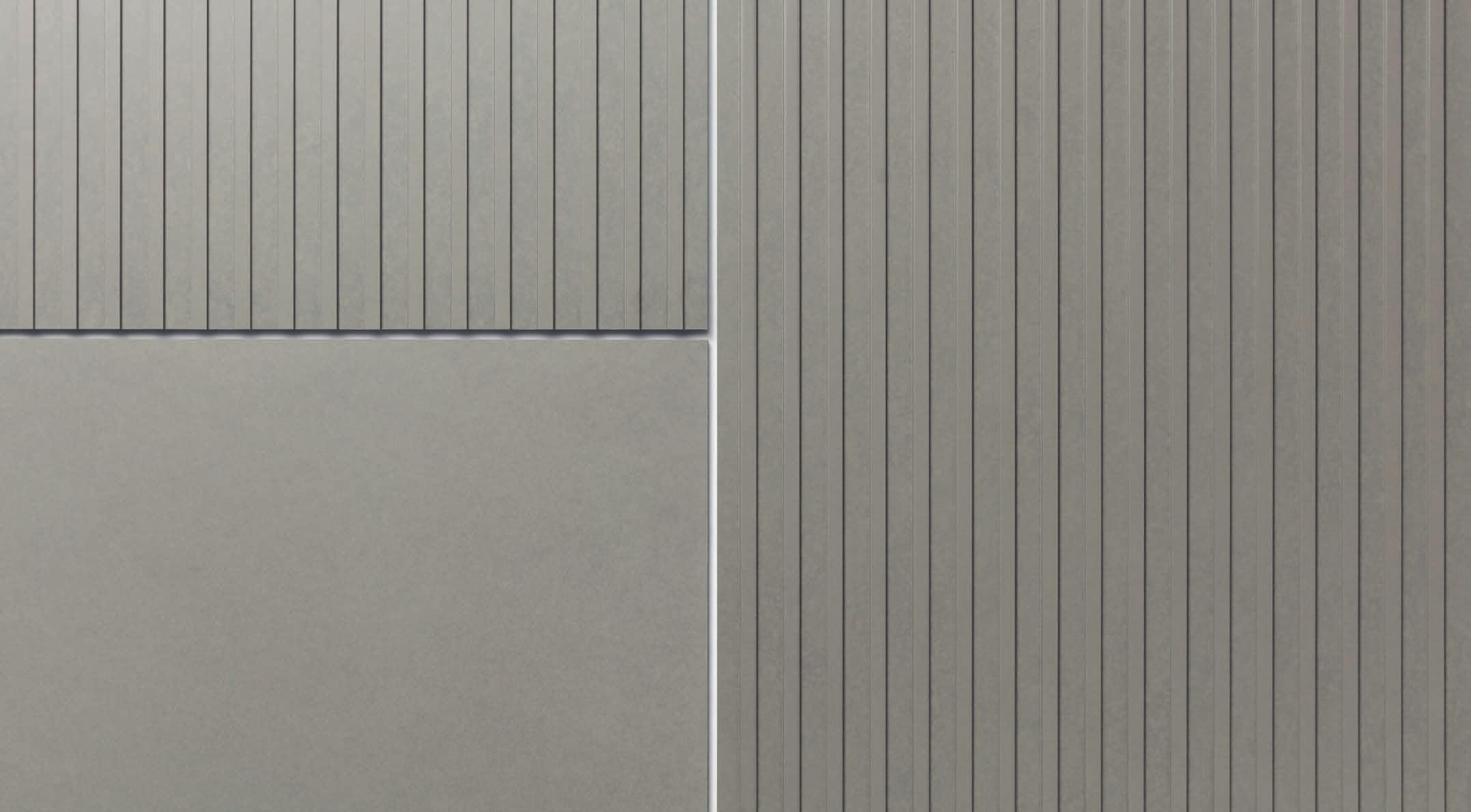
The installation of Gravial panels is thought as vertigal grids, in order to avoid dust sitting on the engravings. Should a horizontal grid be considered, technically possible, keep in mind that dust might sit and stain the panels.
Remove algae / fungii with a 5% solution of hydrogen peroxide (H2O2) to eliminate all spores.
For the use of masking tape on panels it should be noted that most common masking tapes are not resistant to UV rays. Such tapes leave behind residues, that cannot be removed without causing damage to panel surface. However the use of the following masking tapes is recommended:
• Masking tape 3M Blue 2090 for temporary application (1 - 2 weeks)
• Masking tape 3M Gold 244 for longer term application.
Calcium based stains:
• Apply a mist spray of a solution of 9.5% acetic acid and water
• Allow to react a few minutes but do not let dry out
• Use high pressure cold water to rinse cladding
Repeate steps 1 to 3 on difficult stains:
