
INDEX
Iterations Documentation
Iteration 1
Test: Angular Joinery (Fail)

-Concept
-Joinery -Design
-CNC Modelling
Final Prototype 4
Test: Installation Sitting on Frame
-Concept
-Used Tools
-Stepover as Pattern
-CNC Modelling
-Prototype on Site
Iteration 2
Test: Joinery & Patterning
-Concept
-Used Tools
-CNC Modelling
-Hooke Park Workshop
-Assembled Piece
Iteration 3
Test: Stepover as Pattern
-Test Agenda
-CNC Modelling
Final Design

Installation piece assembled on site
-Concept
-Tool Paths Round 1
-Tool Paths Round 2
-Installation on Site
-Self Evaluation
Iteration 5
Tolerance Test
Tolerance Test for future joinery profile offset adjustment
Concept
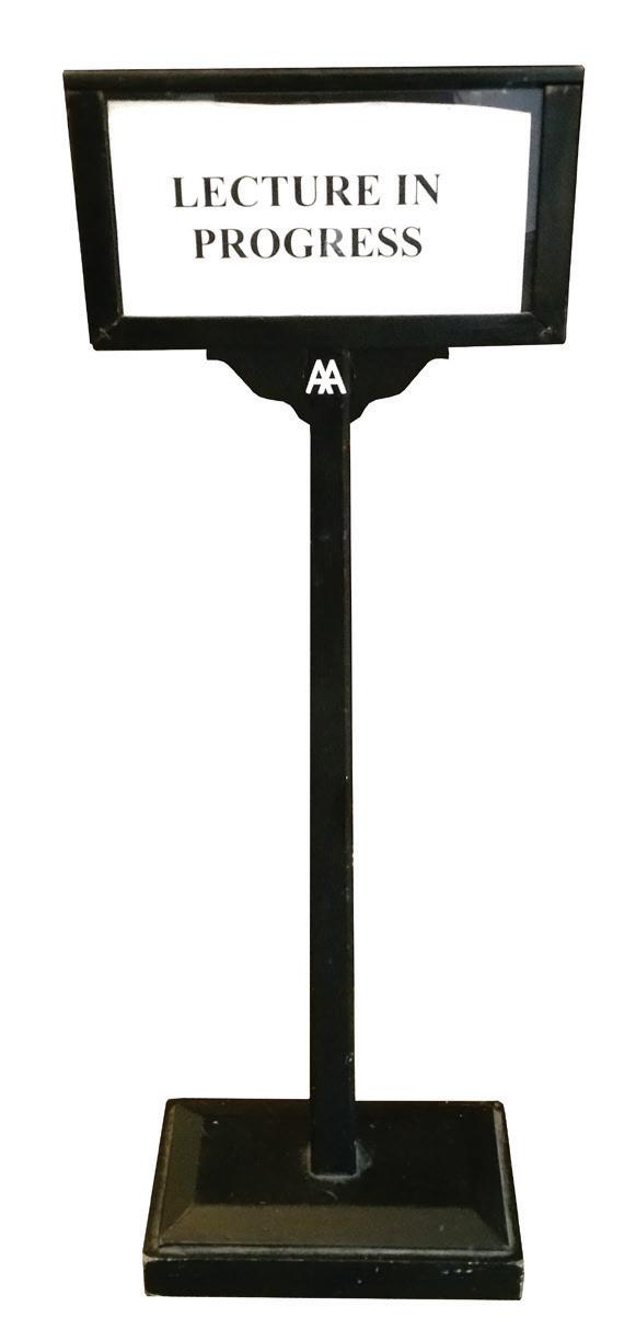
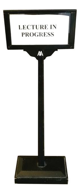
Whenever the Lecture Hall is being used, there will be a sign sitting outside stopping people from entering. However the sign do little in stopping people from entering the lecture hall abruptly. The installation is therefore, aimed to raise awareness of people before they rush into the room.
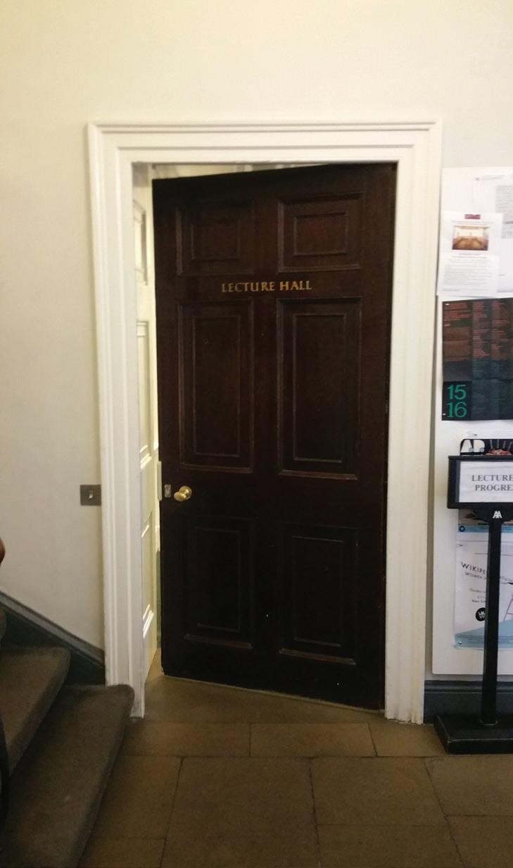
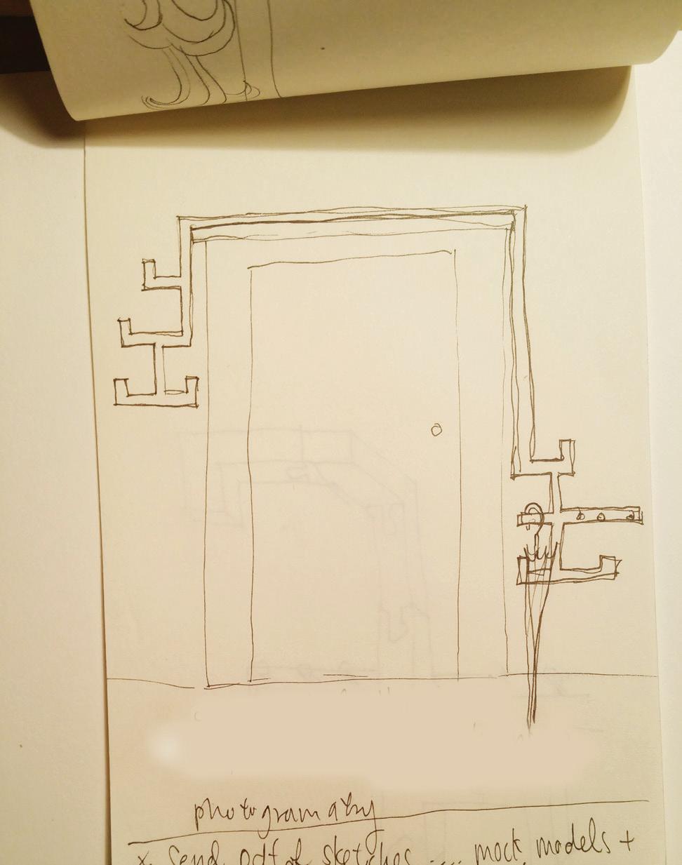
In order to achieve this, the installation would act as a coat/umbrella rack , like a frame it will slot onto the existing door frame of lecture hall. And whenever the lecture is being used, people will hang their coats and umbrella outside on the frame and therefore letting people know it is being occupied before their entry.
ITERATION 1
Traditional Joinery

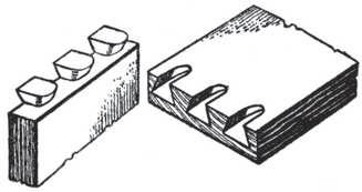
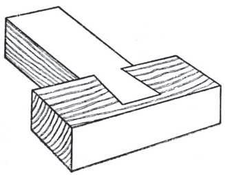
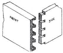
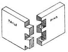
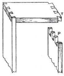
Aiming to achieve the installation economically I am aiming to do it out of scrap, and thus it is aimed to be assembled with timber itself.
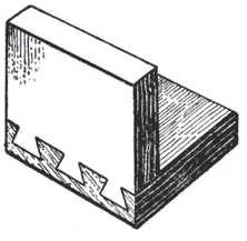
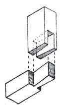
I was looking for joinery which requires the minimal effort which doesn’t require another material, hence I started looking at Japanese Joinery.
ITERATION 1 Design
The design is comprises of 5 standardised element with sophisticated wood joints. CNC would provide the precision in making of these components. Which is important for assembling the installation.
My next step would be making a few pieces to see if they can be assembled perfectly.
ITERATION 1 CNC Modelling
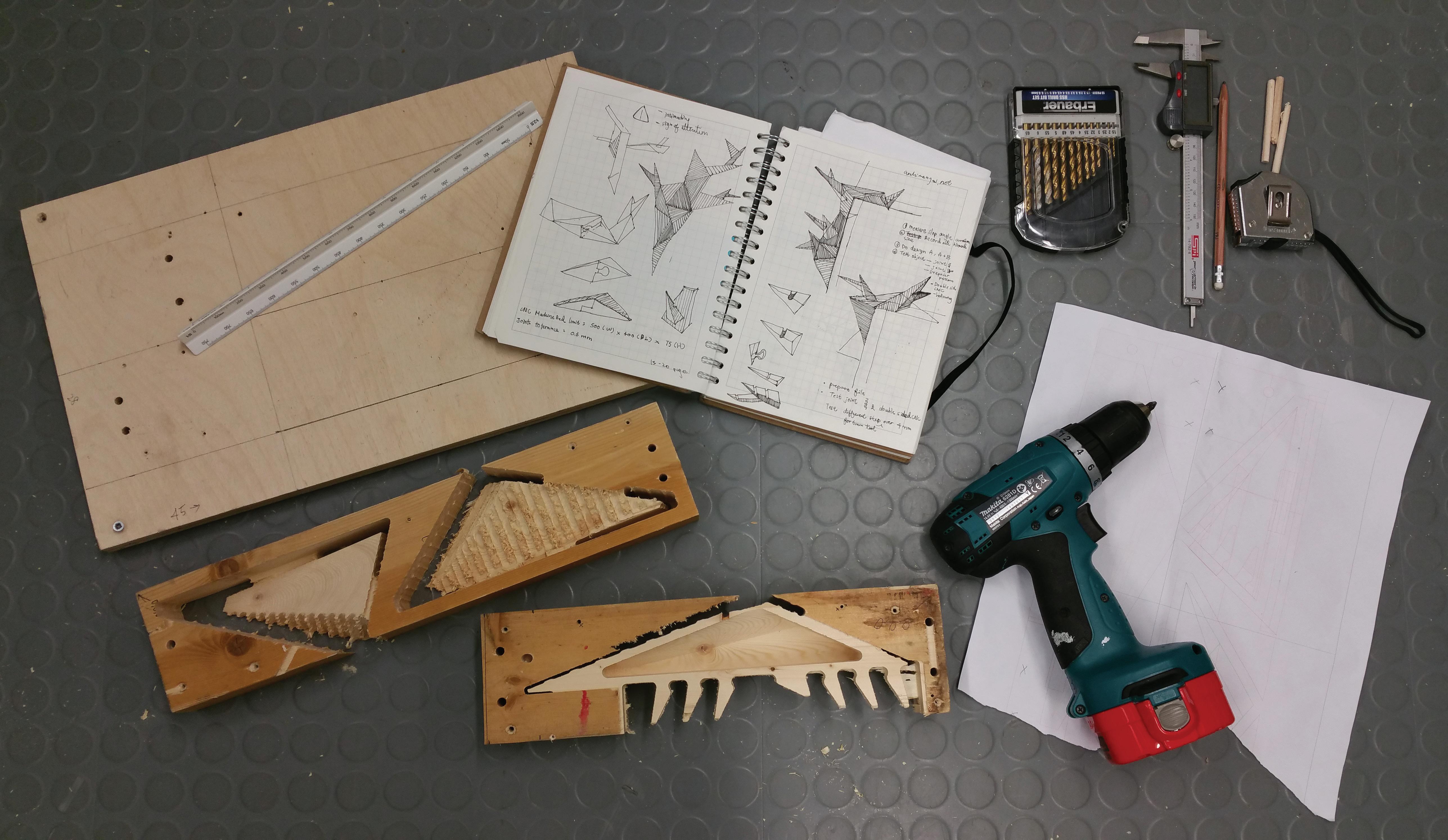
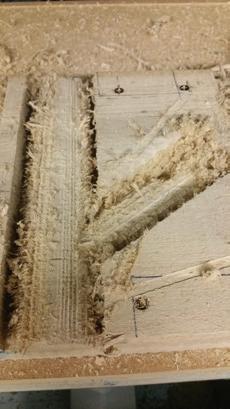
The design of the connection is made so the joint would be part of the hooke for hanging coat , but after the first attempt with the CNC machine it is realised that angular corner of the inner side of the profile is hard to achieve.
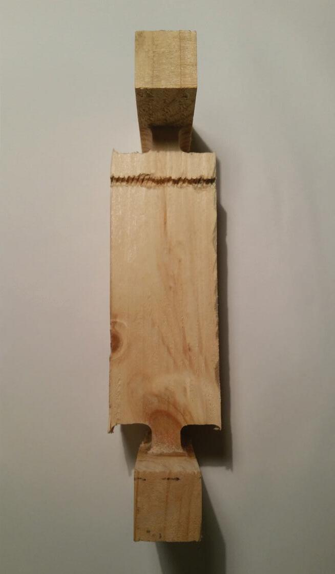
Secondly, the way to achieve an extended joint as hooke result in waste of materials so it may be unpractical for the current form.
Tool Setting:
Failure:
1. It is discovered that due to the round nature of all tools, it would be impossible for CNC to archive any sharp angle in the inner perimeter of the piece.
Concept
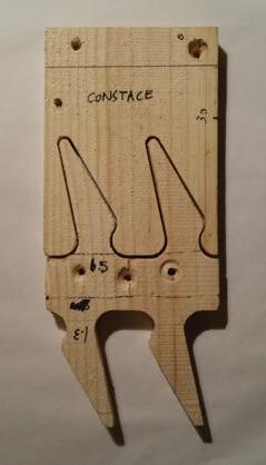
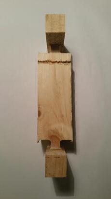
The second prototype continues to explore joinery but in a more 2D form. I also change from angular inner corner to round edge for the profile of joinery as it seems more practical for the CNC machine.
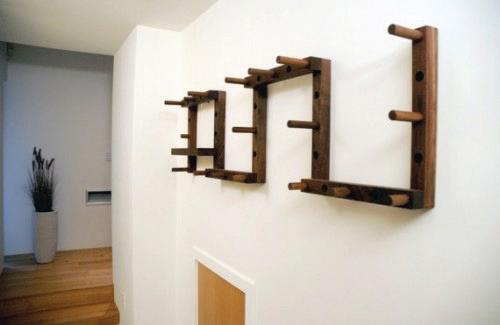
I then explored with other tool from the workshop and together the CNC prototype I made a coat rack.
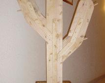
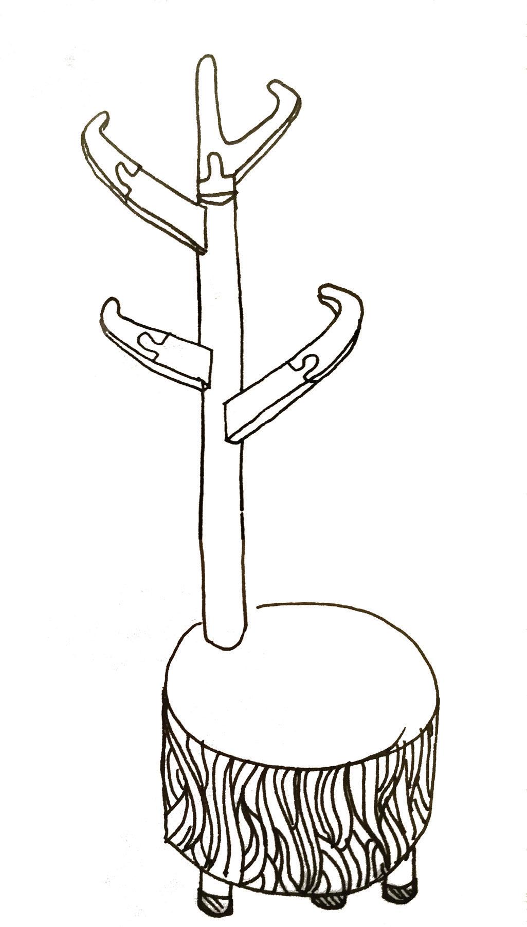
I also want to achieve the piece with different pieces that can slot together as I aimed to used collected scraps to make the piece.

ITERATION 2
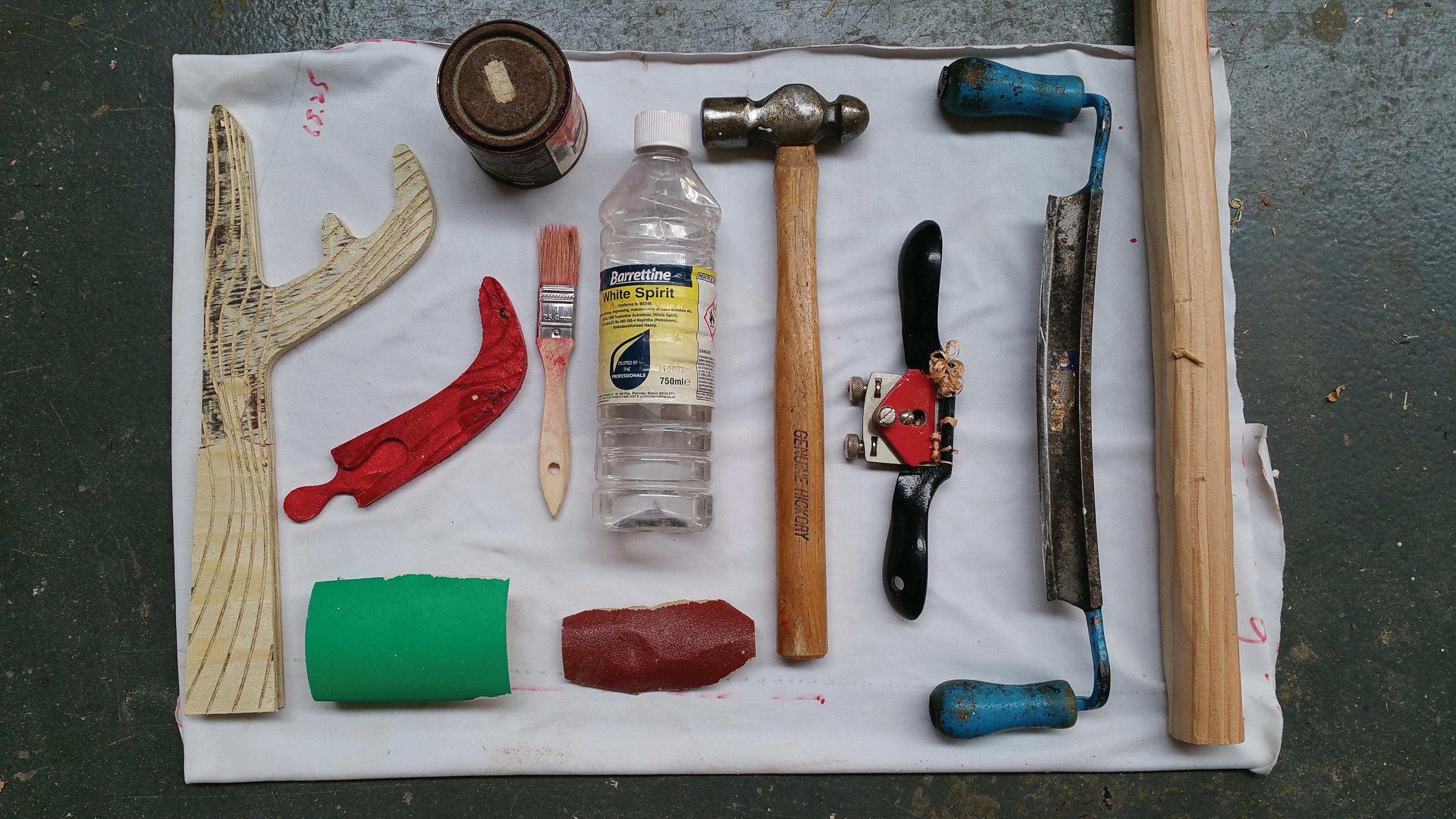
Used Tools
ITERATION 2 CNC Modelling
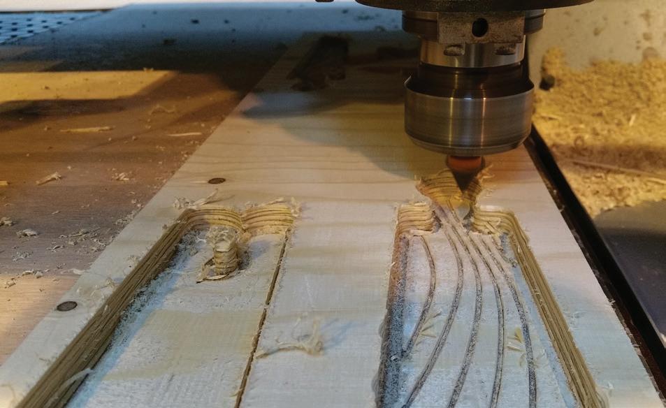
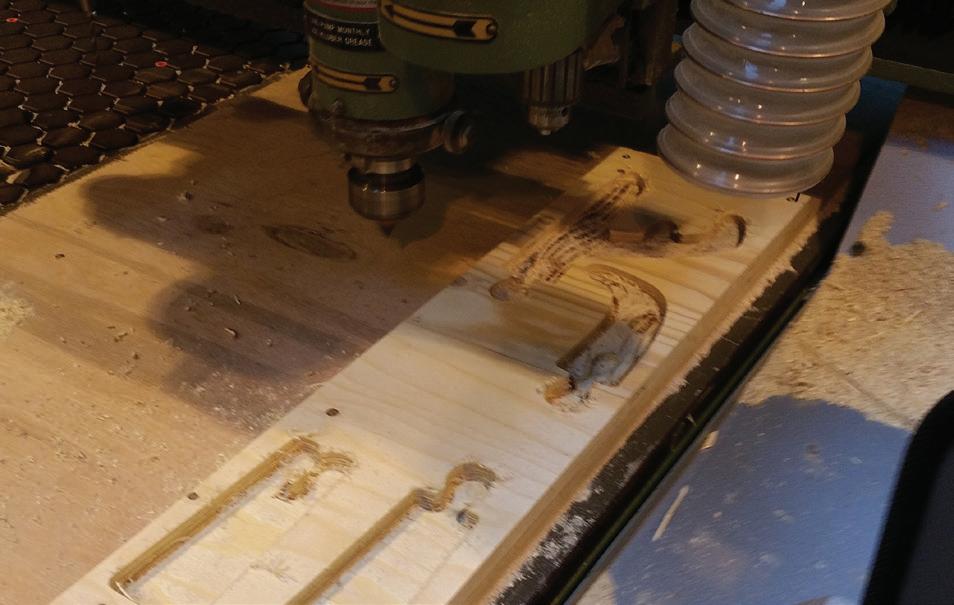
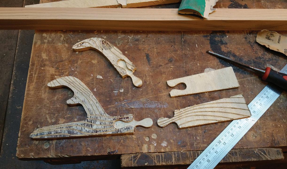
First the profile is cut around the panel until 1mm above ground so that the pieces can be plug out easily when done,.
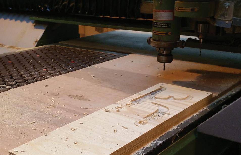
Then 2D excavation is done twice according to the different thickness of panels, by removing materials from above until the right thickness is reached. At last there is engraving done on the surface,
Tool Setting:
ITERATION 2
Hooke Park Workshop
ITERATION 2
Hooke Park Workshop
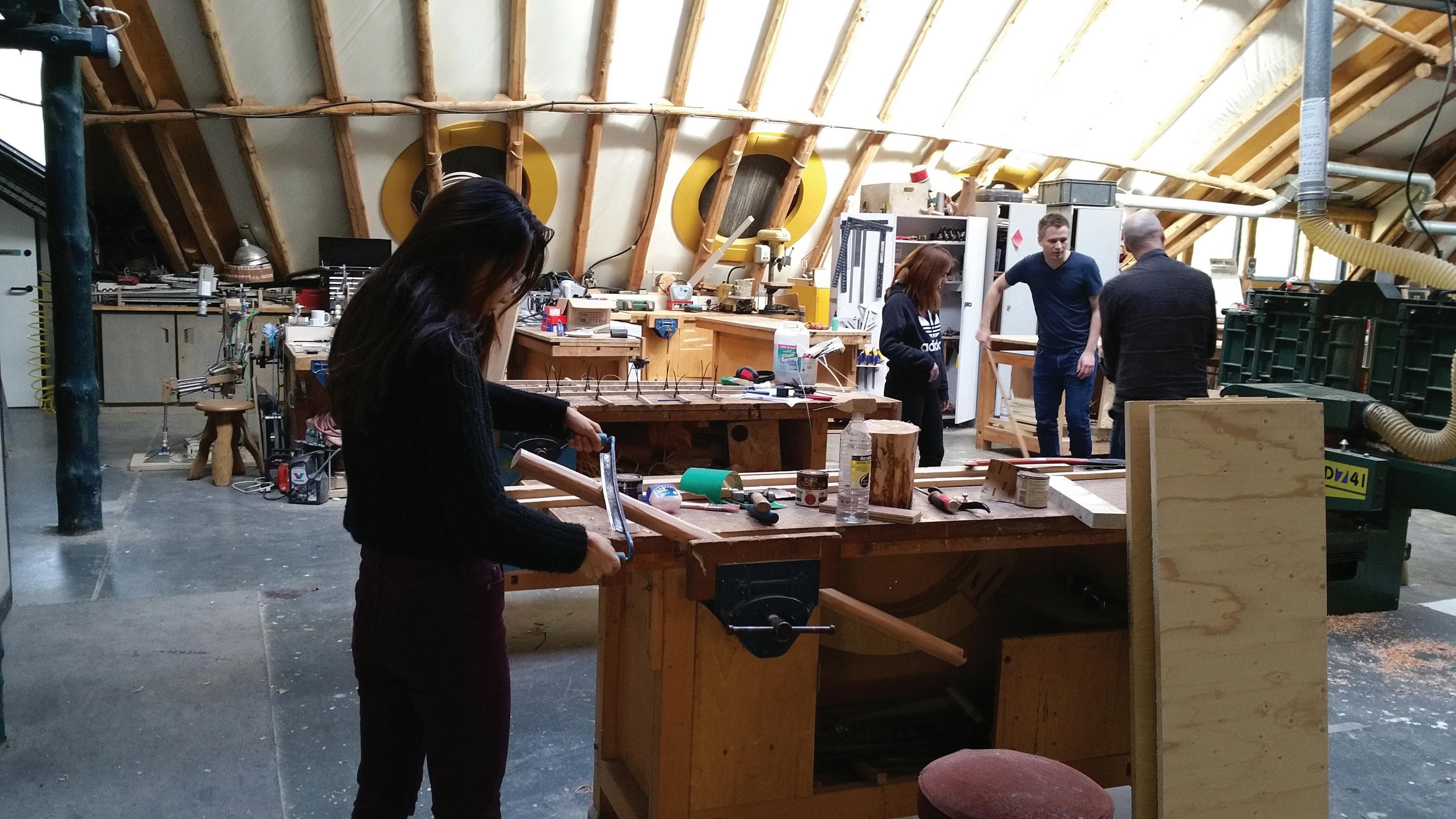
For the CNC parts, a lots of sanding took place in order to be able to put the pieces together, it is perhaps the offset is too little or the way the CNC cut it wasn’t right.
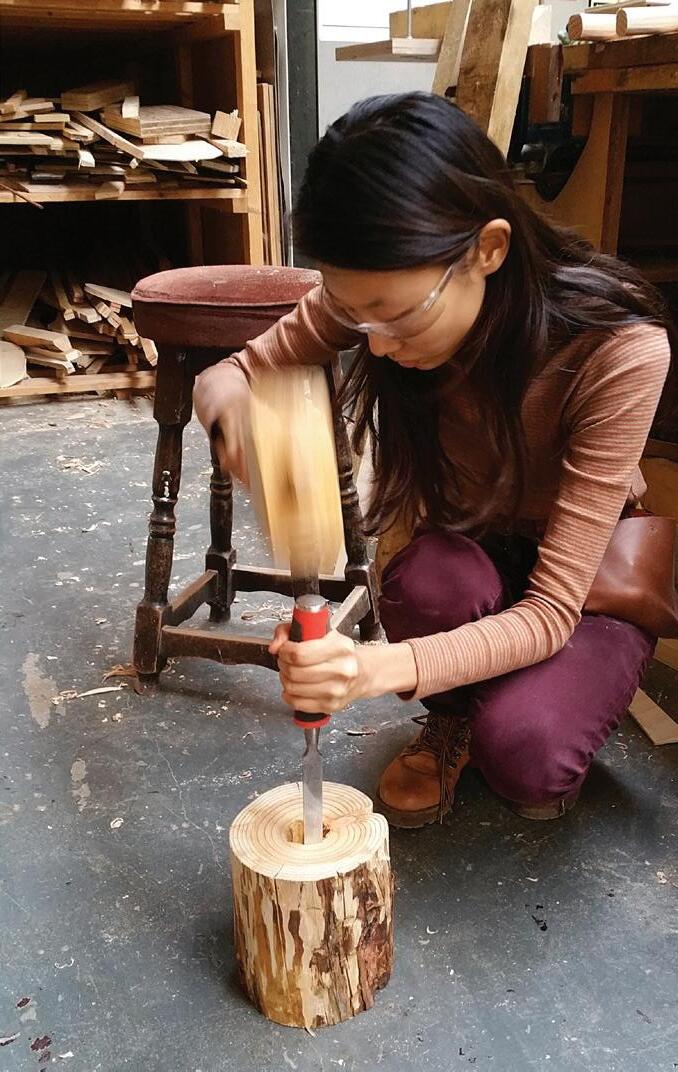
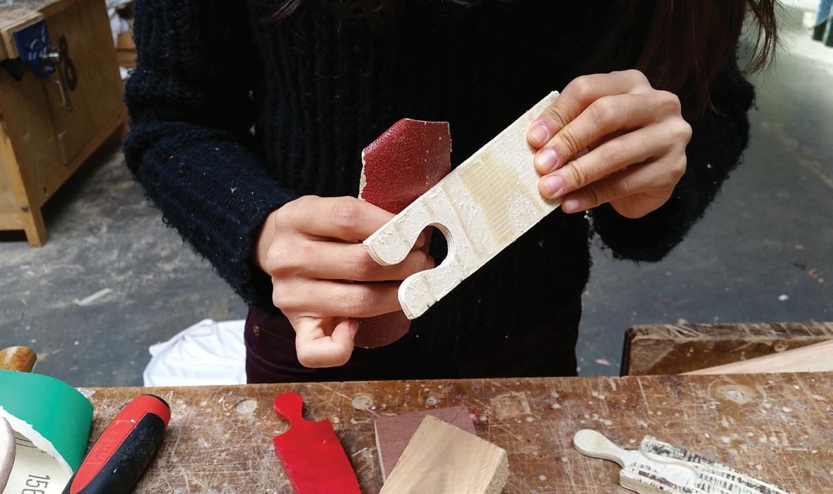
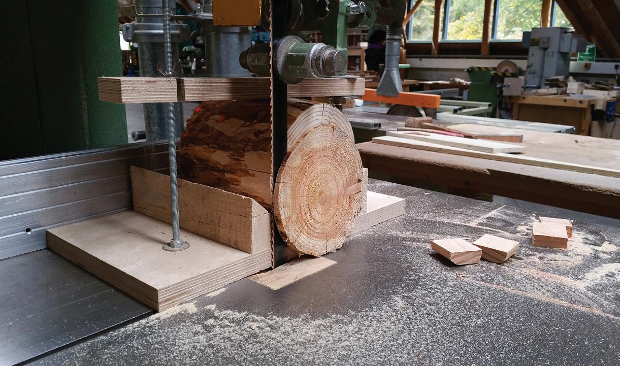
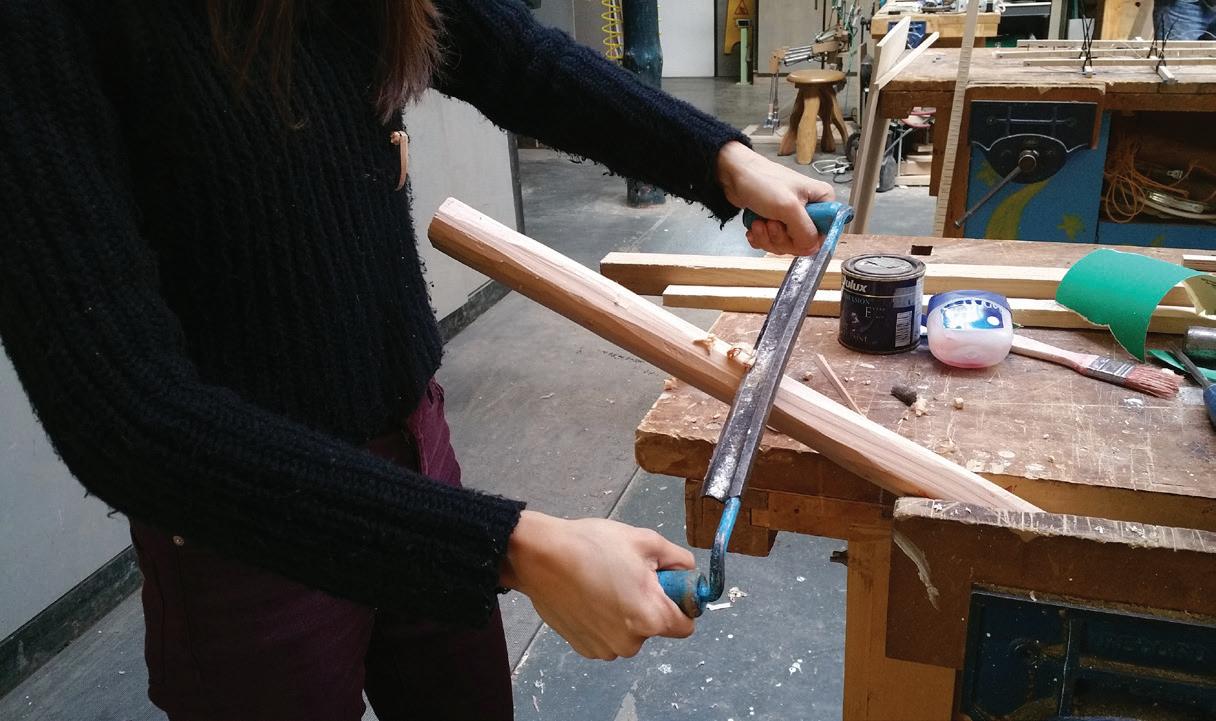
For the other parts of the coat rack I explored other different tool at Hooke Park Workshop.
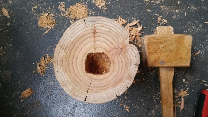
ITERATION 2
Assembled Piece
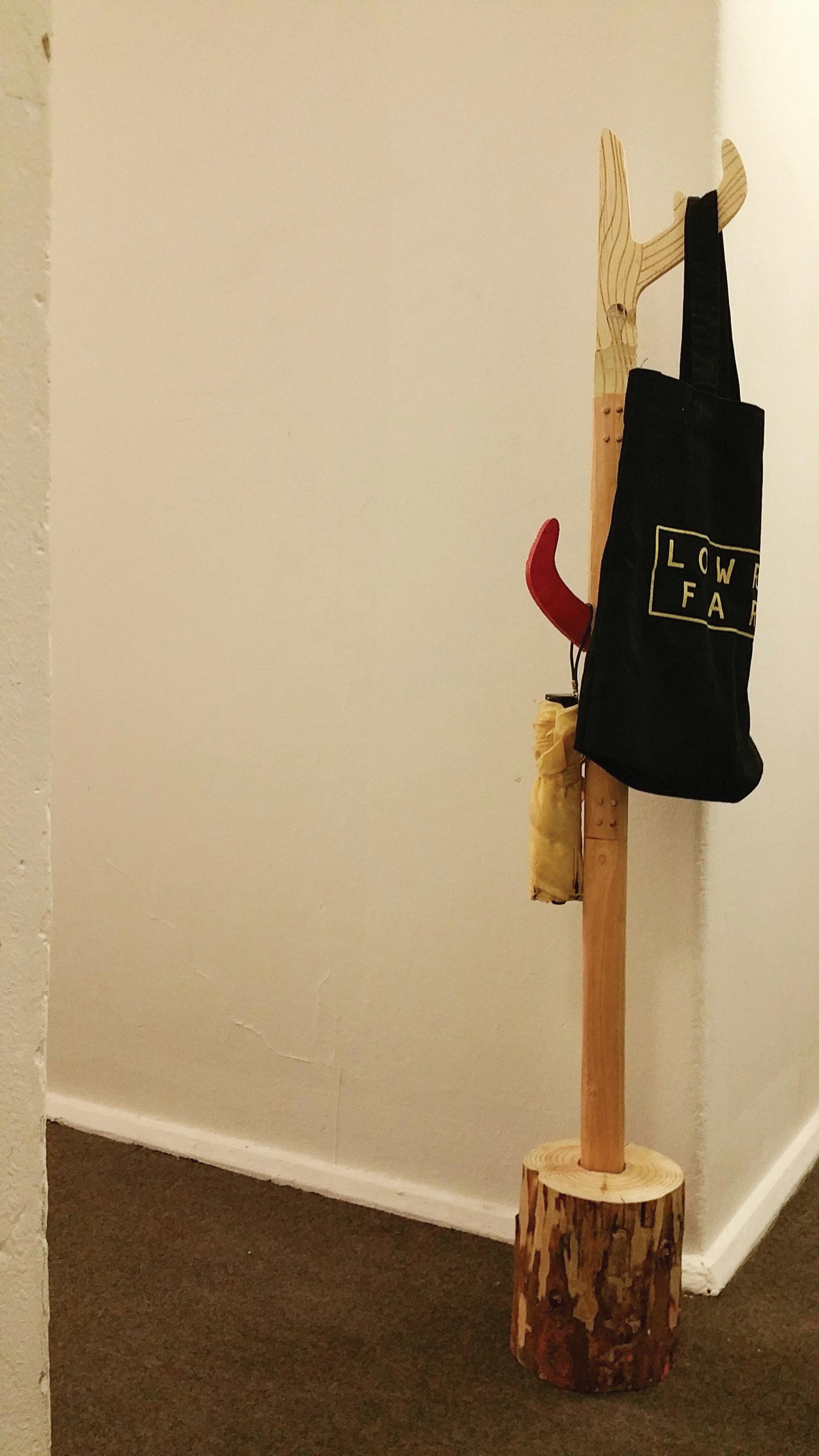
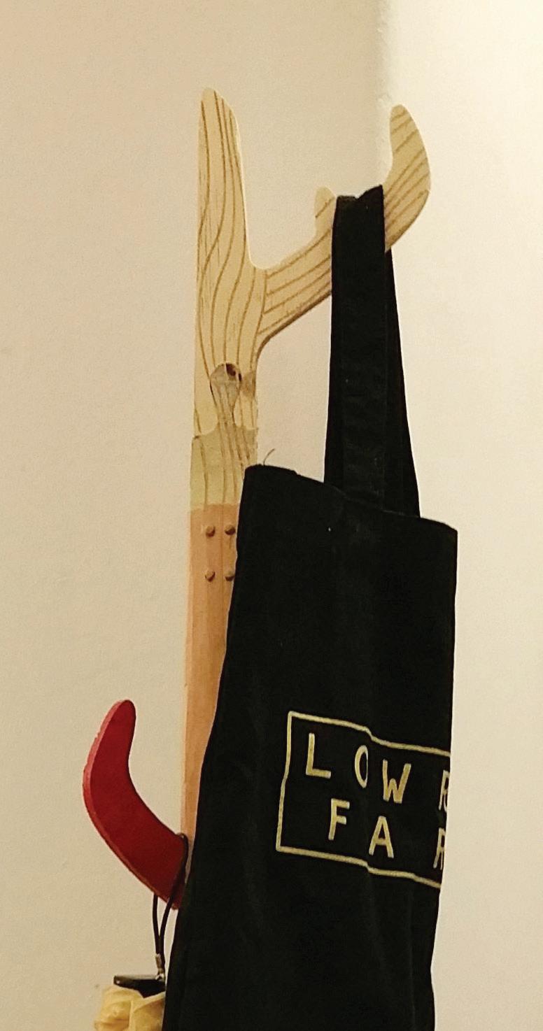
This happen to be the first time I made any furniture and it is quite rewarding to achieve the piece with both traditional wood craft method and CNC at the same time.
It is essentially an assembly of all sort of experiment I did in Hooke Park Workshop. From The CNC puzzle joinery to the traditional lap joint. And different way to treat the wood piece such as painting it and or leave it as it is ,etc.
Overall, I am quite happy how the piece turn out aesthetically and practically as a usable furniture.
After the iteration 2, I wish to explore how patterning can be done with the CNC tool itself.
Prototype 3.1 & 3.2
An attempt to explore other texture possibility with CNC
3.1
Simple form but planning on doing only fine roughing and find out how aesthetic it can be.

3.2
Explore CNC in a slightly complicated form to experience the logistic in setting up to do this small scale of curvature.
The outcome will help me to make comparison with previous way of doing pattern and hence inform me which technique I will employ for later design.
ITERATION 2
CNC Modelling
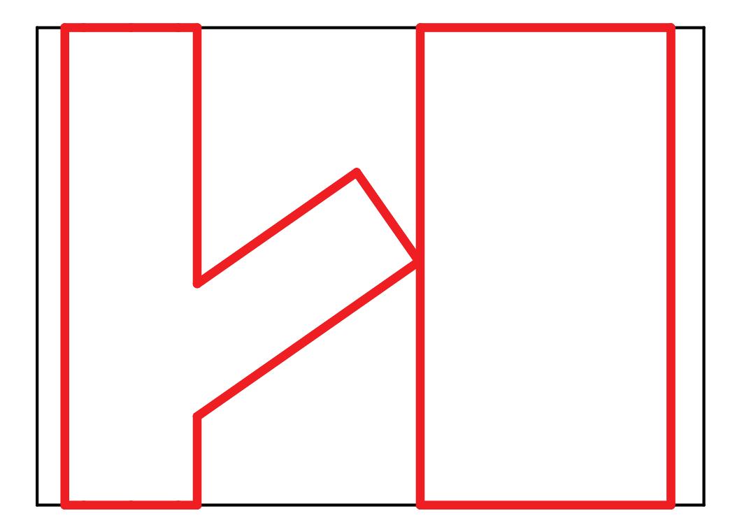
1. Roughing 6mm End Mill
* (Roughing area is a 8mm offset from the actual model so there is space for tool to go down during finishing)
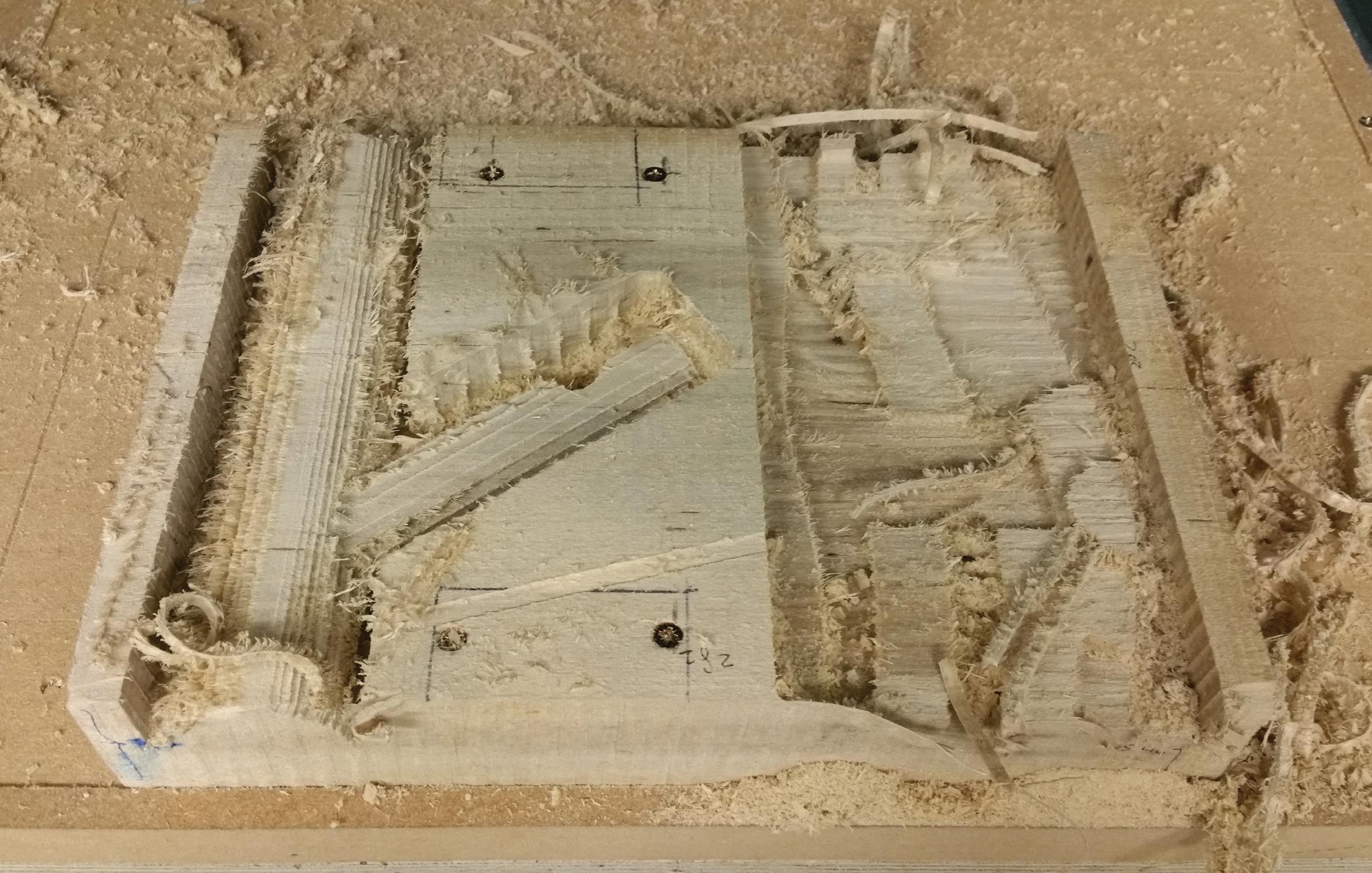
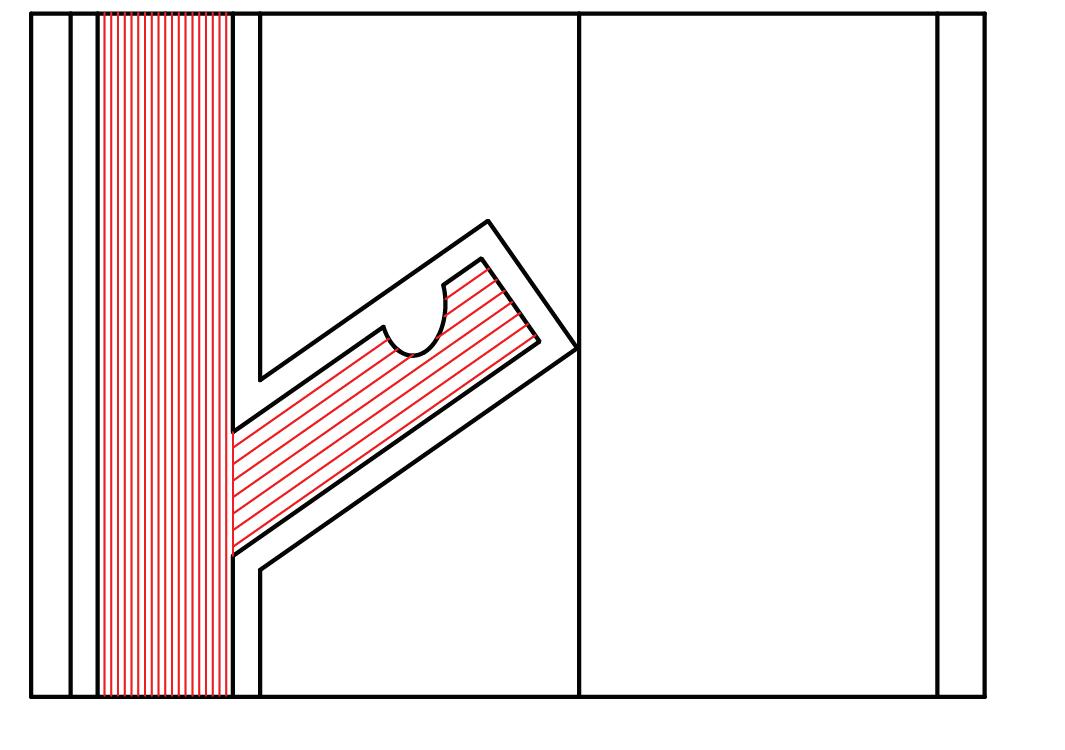
2a. Finishing 6mm Ball Nose - Stepover 2mm
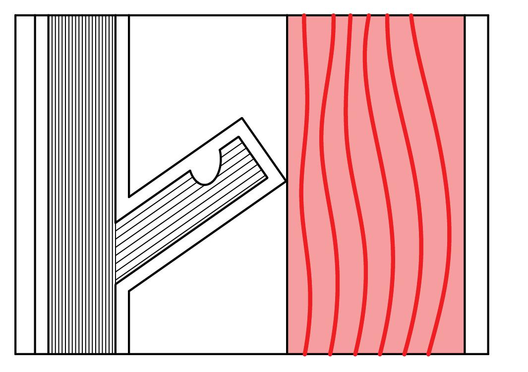
2b. Finishing 6mm Ball Nose - Stepover
Failure: When the Wood is too wet it is very difficult to do perfect finishing on both side.
Success: It is possible to do pattern by manipulating the stepover for finishing. (Right hand side)
3a. Roughing 6mm End Mill
3b. Finishing 6mm End Mill-Stepover 0.5mm
Final Prototype
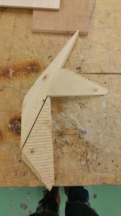
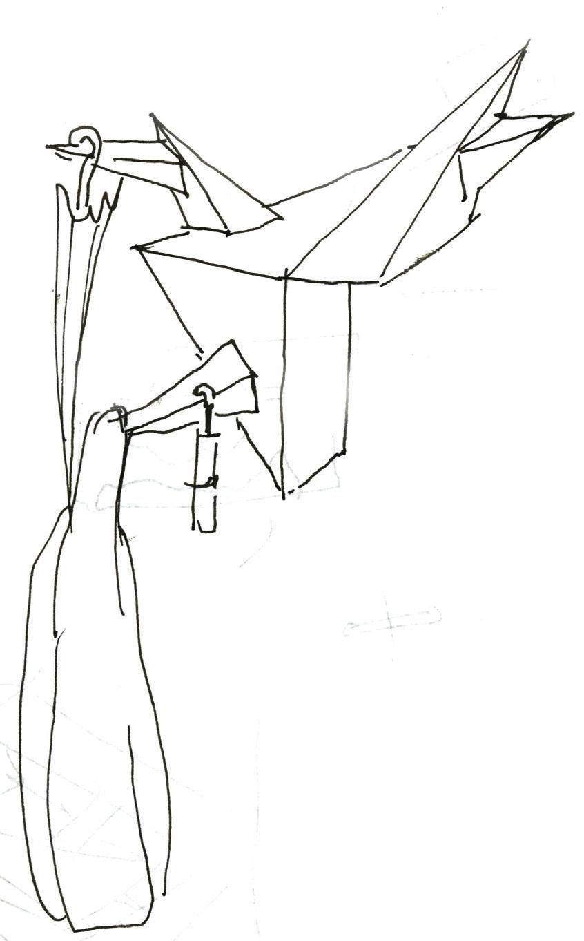
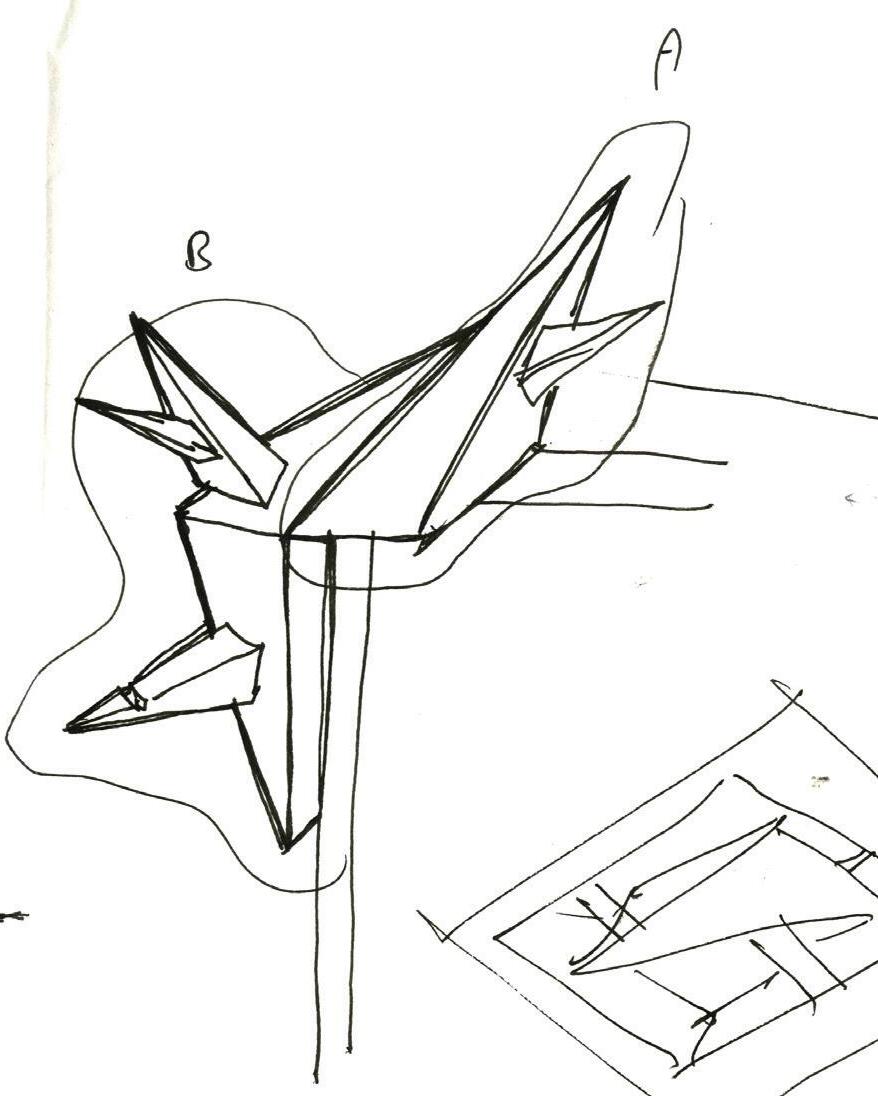
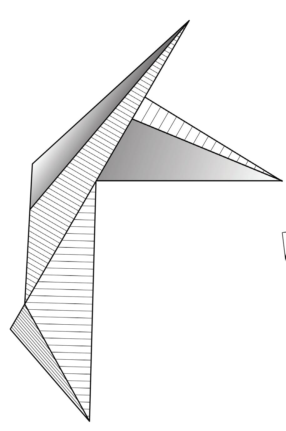
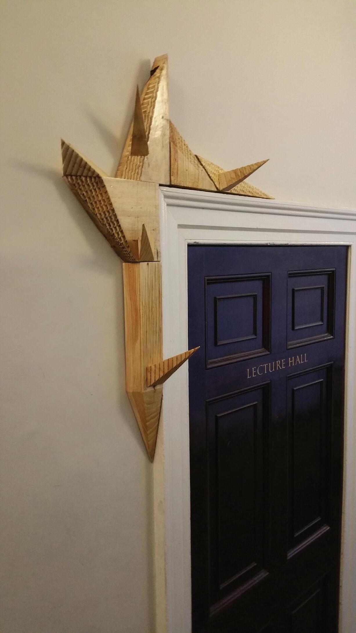
Each dimension of piece is determined by the scraps’ size I collect. The angular and pointy geometry is meant to raise awareness to people as an installation- to rethink if the lecture hall is empty before entering.
Installation will sit on the frame and Part A should weight more than B so the installation can support itself sitting on the frame without addition reinforcement.
The pointy element will also act as hook for users of lecture hall to hang their coat or umbrella before entering the lecture hall. The inhabitants therefore in a way contribute in how the installation will look.

ITERATION 4
Tool Used
ITERATION 4
Stepover as Pattern
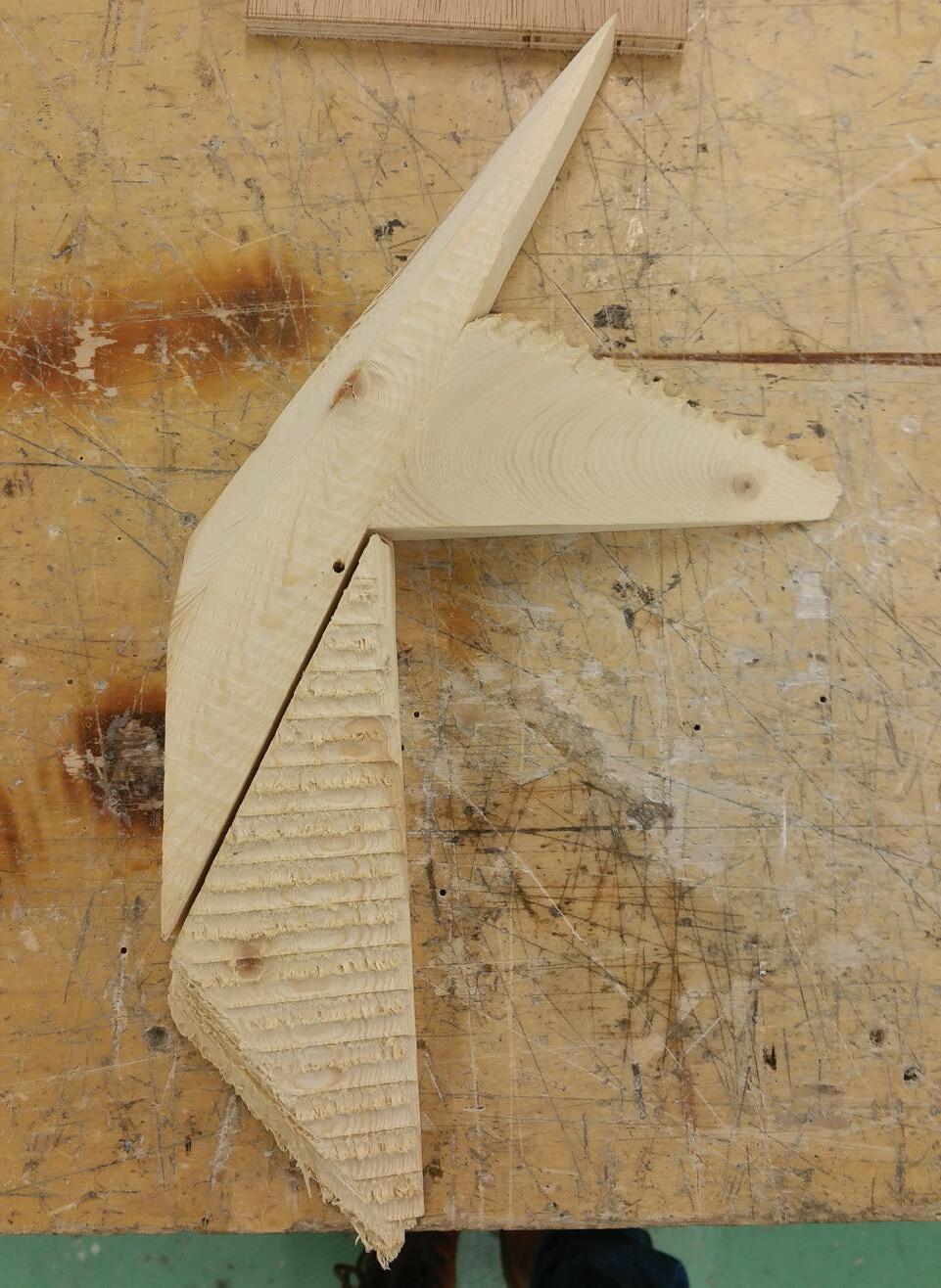
In this piece various of pattern is made by changing the stepover value ranging from 0.5mm to 8mm to create finishing such as strips , coarse and smooth surface.
Stepover 0.5mm (Smooth Finishing)
Stepover 8mm (Clear Pattern, but deeper than 6mm)
Stepover 4mm (Still Smooth)
Stepover 6mm (Clear Pattern)
Stepover 2mm (Clear Pattern)
ITERATION 4 CNC Modelling
Round 1
1a. Set up a timber plate under wood piece (Total height do not exceed 70 mm)
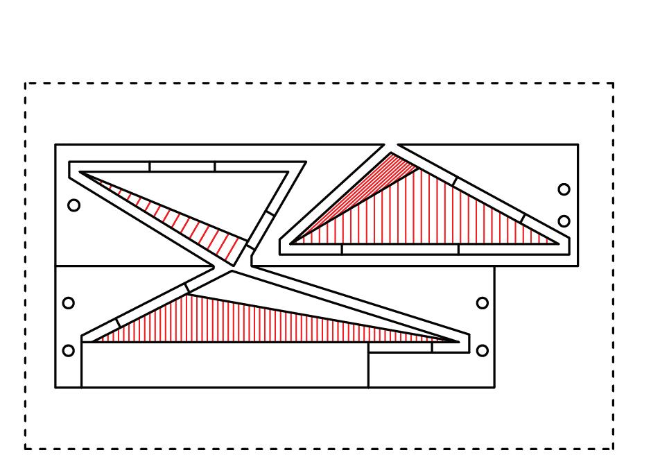
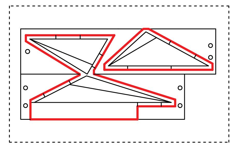
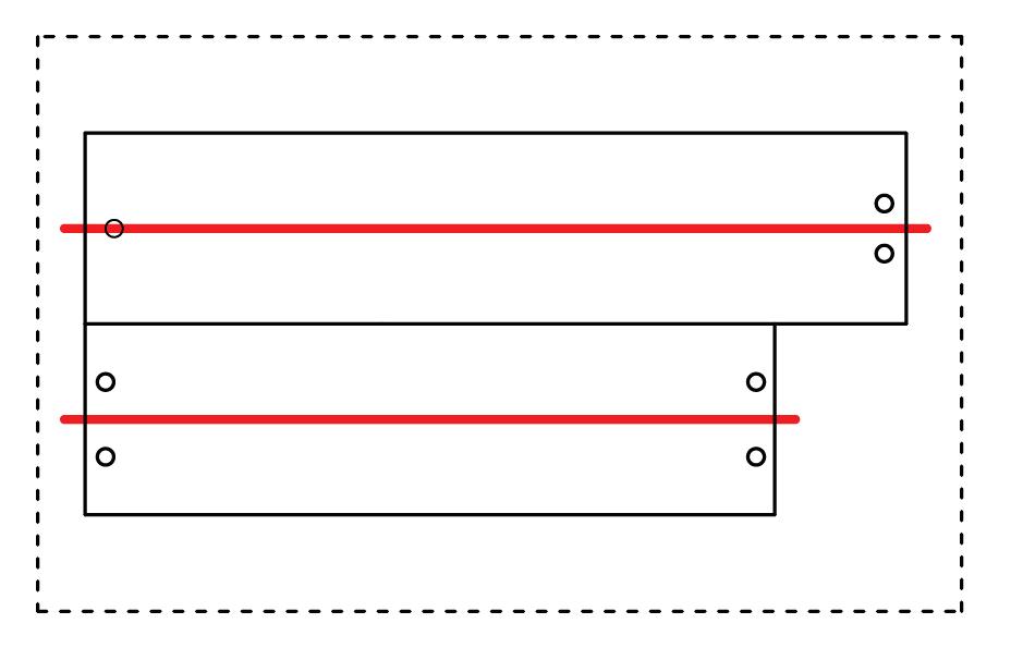
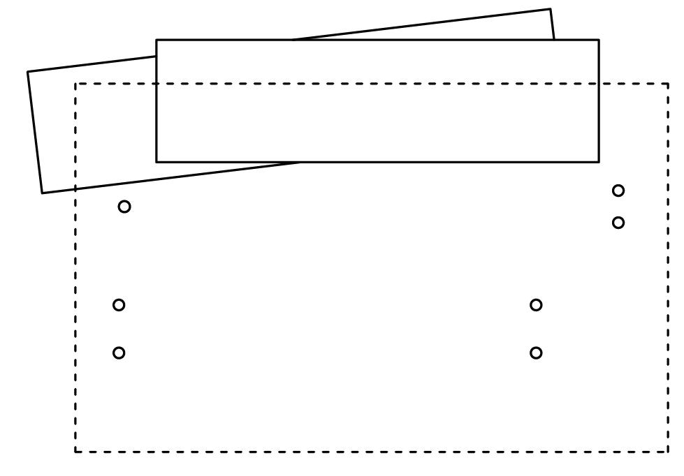
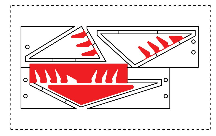
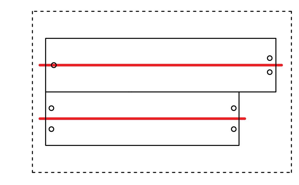
1b. Drill holes of diameter of 6.4mm with 6mm End Mill, for the depth of wood piece as well as wooden plate . (Holes are in symmetry)
3. Remove pieces and turn upside down, there are marks on both wood piece and wood plate
4. Set up the location of the wood piece by slotting in bosom wood (6mm) so it would be at the same location as before but up-side down.
ITERATION 4 Prototype on Site
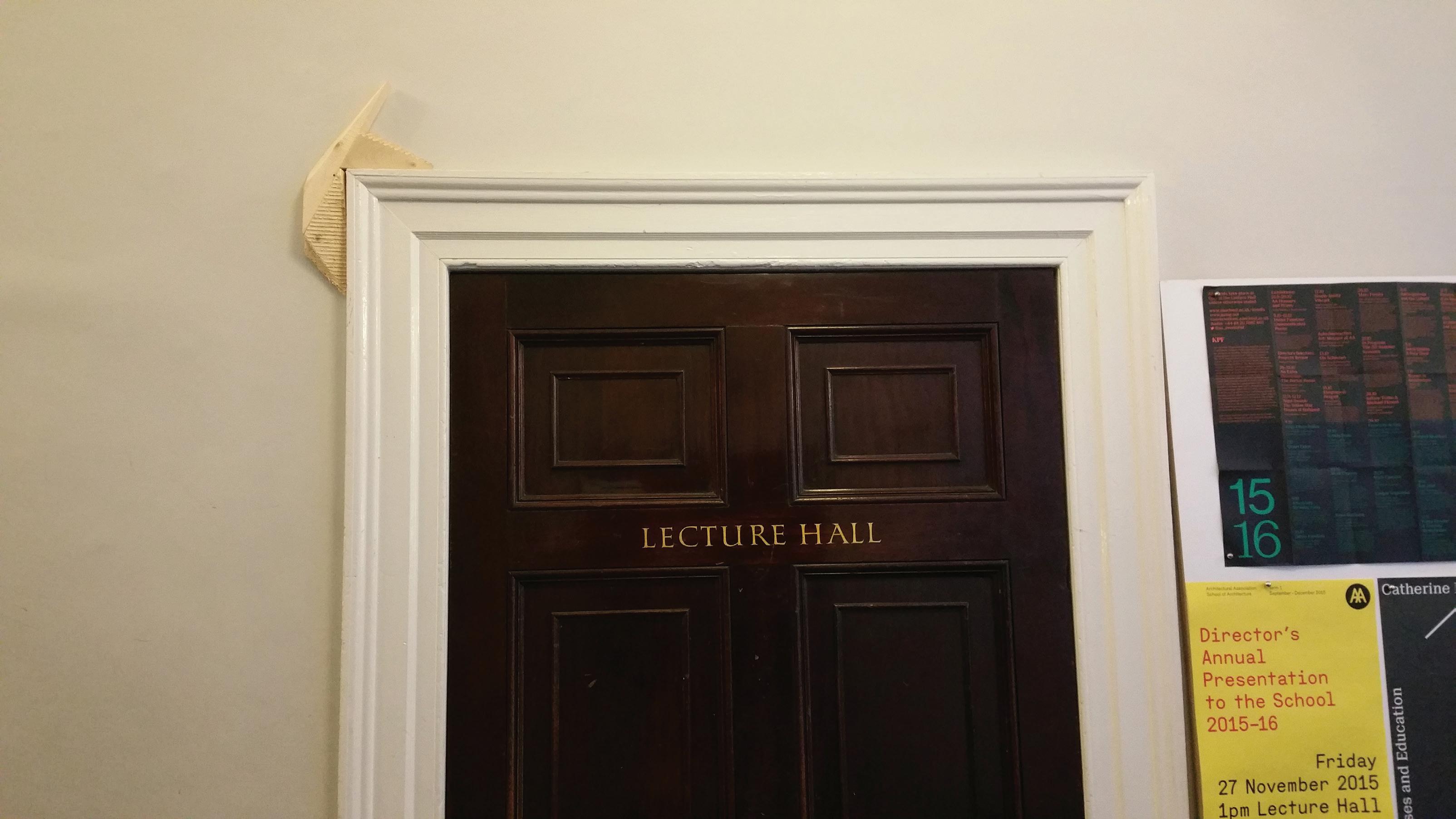
In terms of scale it will probably look nicer if it is bigger
Tolerance Test
Since the installation relies a lot on joinery putting pieces together,but that it has been difficult to assemble two pieces of CNC component together, I have decide to find out the reasons of that.
Given the general tolerance offset is 0.3mm, I have tested a several variable base on that, which is 0.3mm, 0.5mm, 1.3mm, 1.5mm respectively.
I also wondered why the previous model didn’t work despite that I gave it a 0.3mm tolerance. Turns out if it is a raster cut it will increase in precision of the profile and will result in difficulties in assembly.
The right way to do it is to use profile cut. Which give a better precision on the components’ profile.
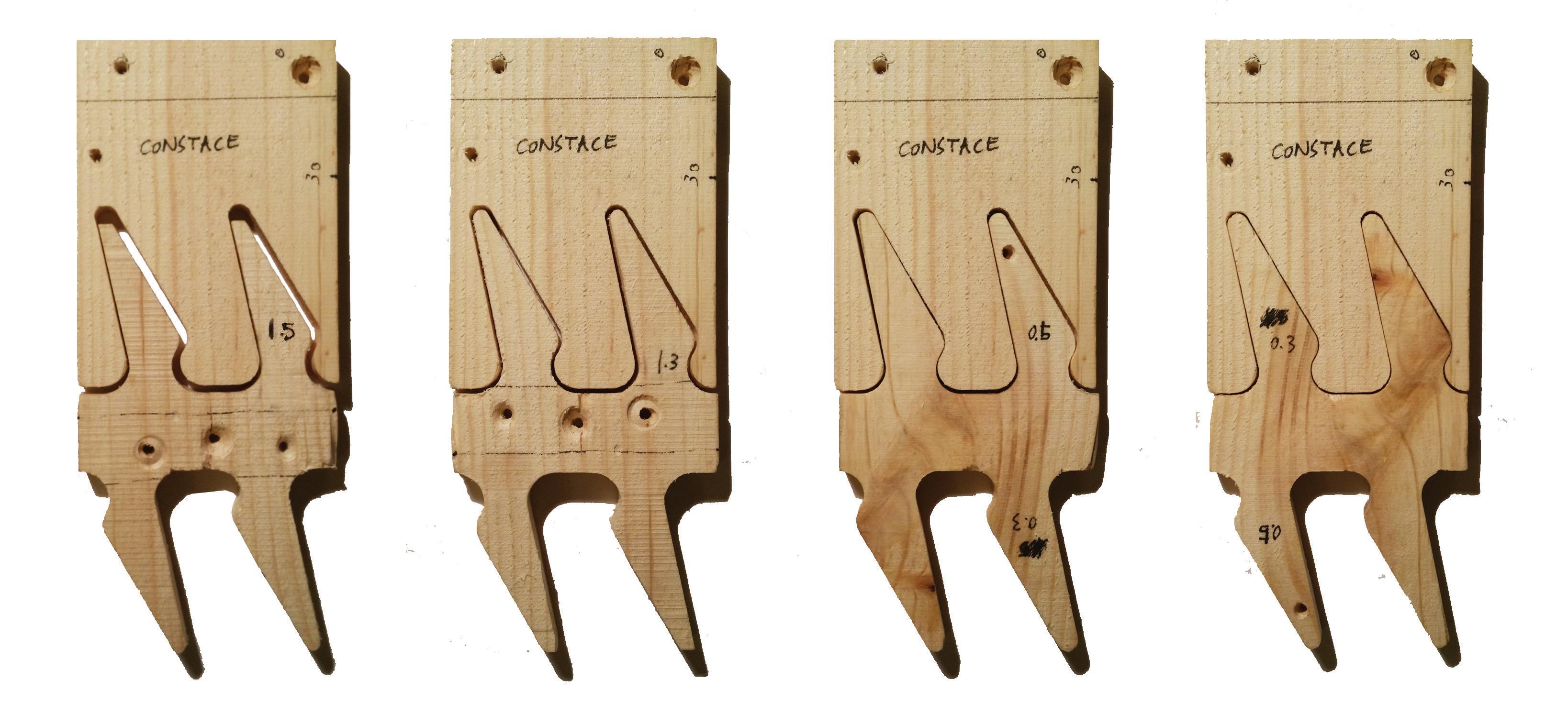
Tolerance: 1.5 mm Too Loose
Tolerance: 1.3 mm Loose Fit
Tolerance: 0.5 mm Comfortably Fit
Tolerance: 0.3 mm Tight Fit
Final Design
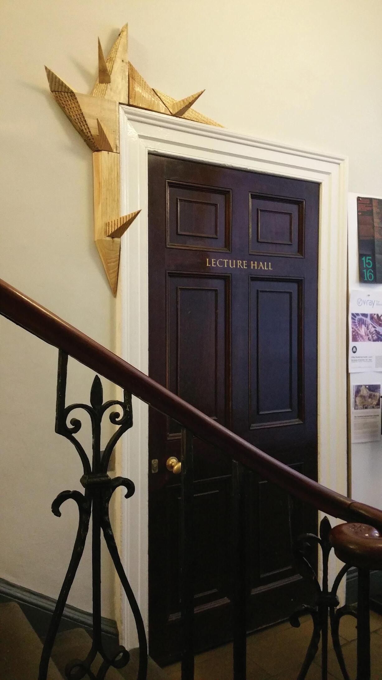
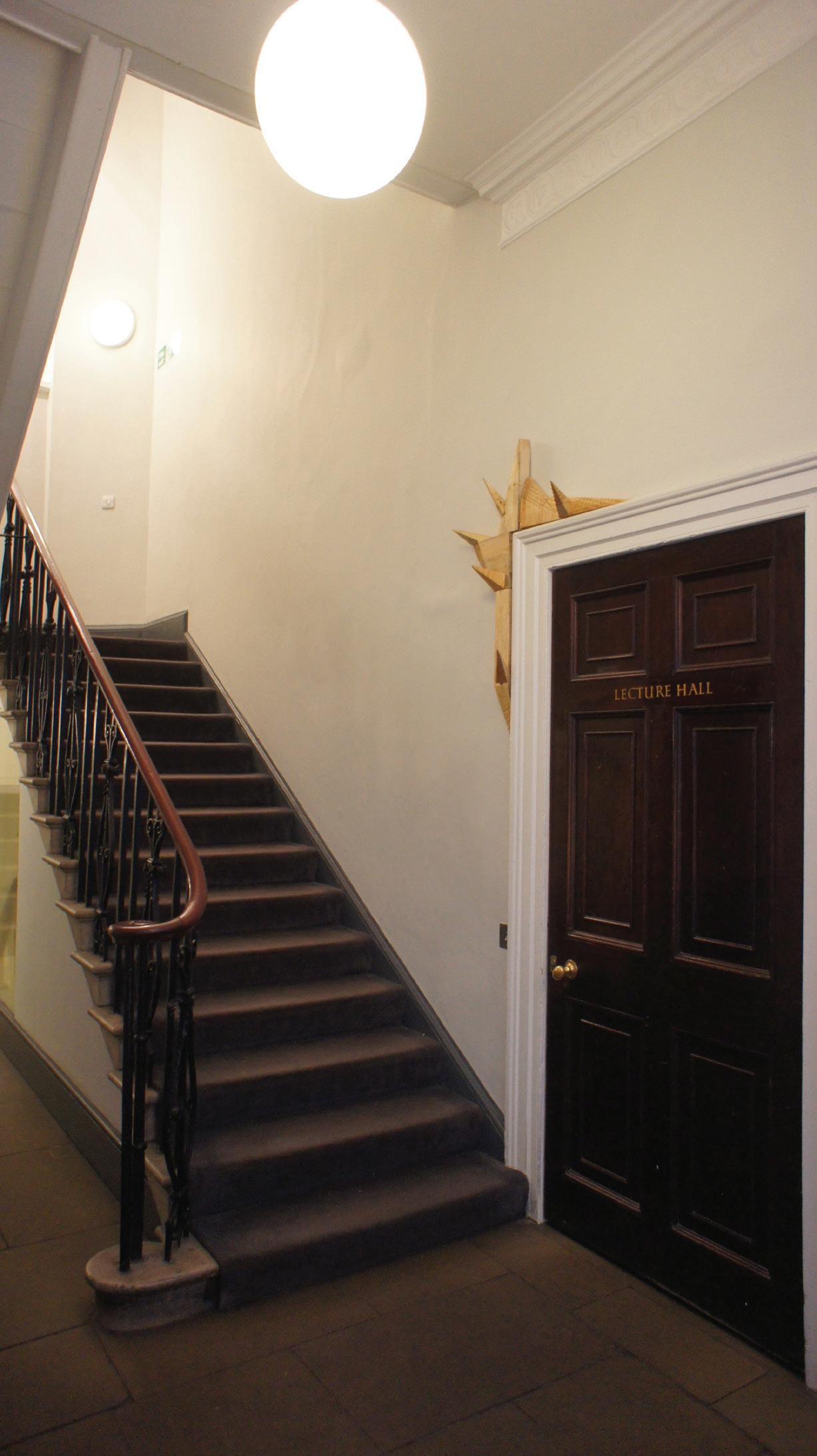
Whenever the Lecture Hall is being used, there will be a sign sitting outside stopping people from entering. However the sign do little in stopping people from entering the lecture hall abruptly. The installation is therefore, aimed to raise awareness of people before they rush into the room.
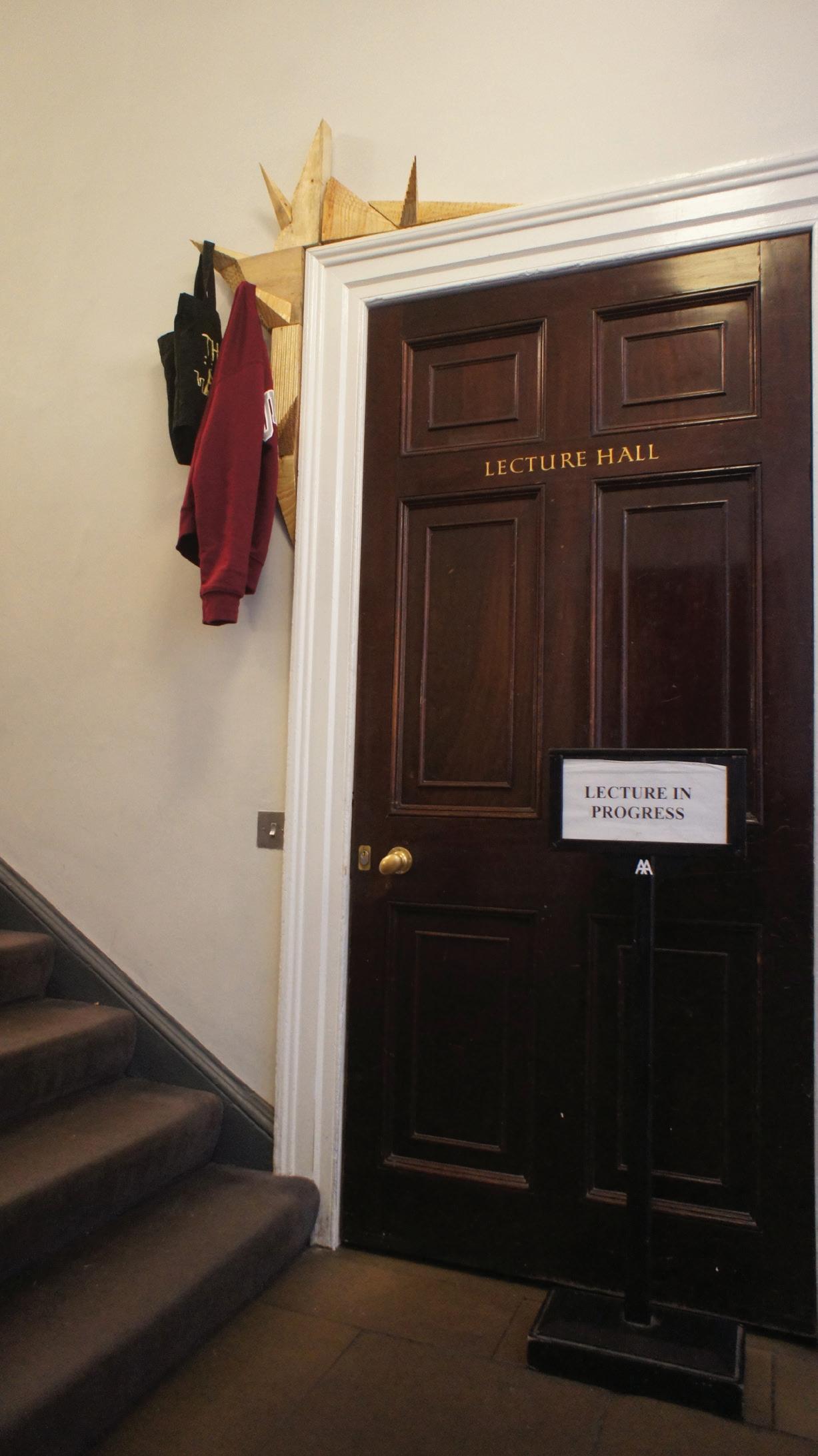
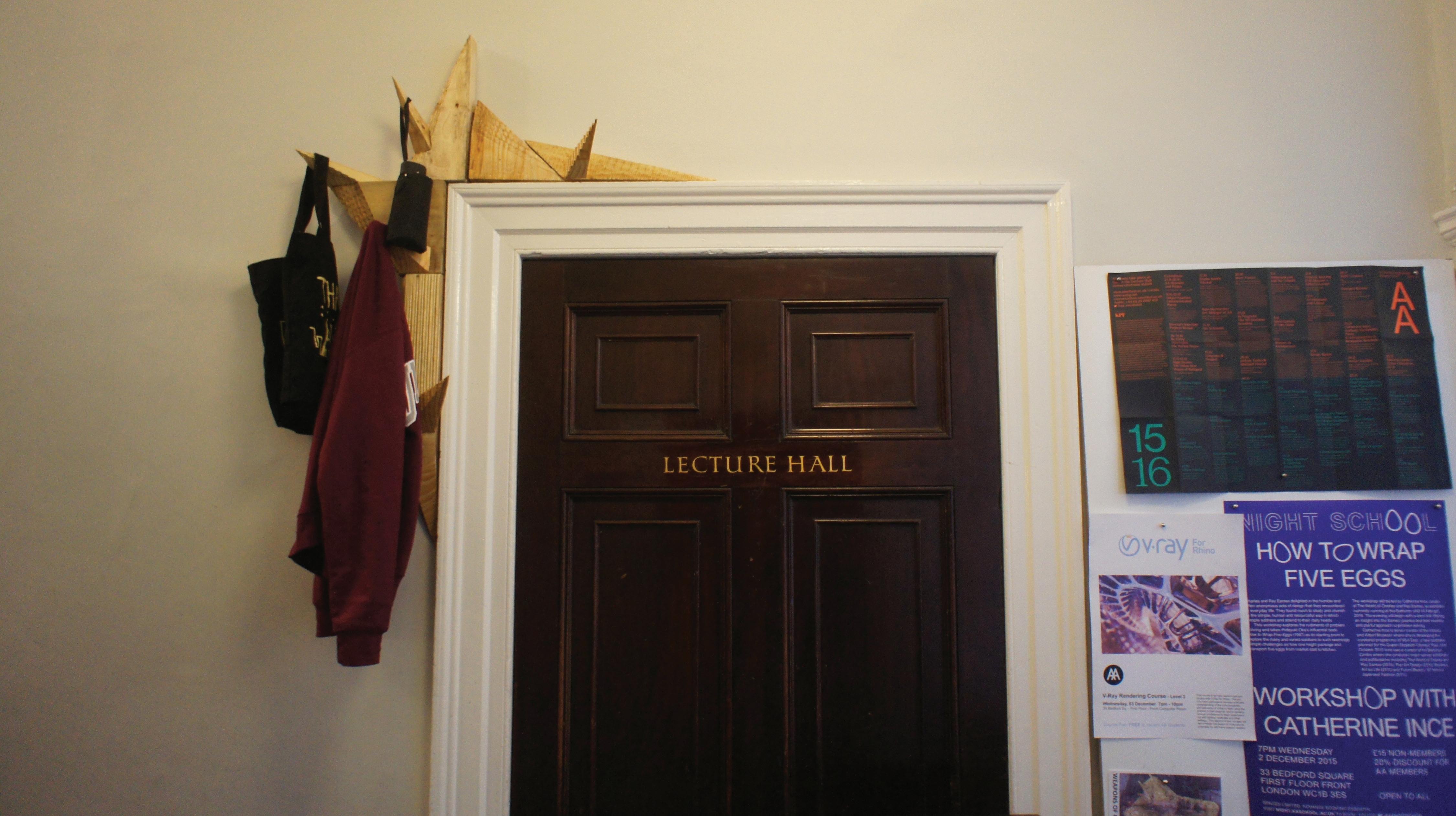
In order to achieve this, the installation would act as a coat/umbrella rack , like a frame it will slot onto the existing door frame of lecture hall. And whenever the lecture is being used, people will hang their coats and umbrella outside on the frame and therefore letting people know it is being occupied.
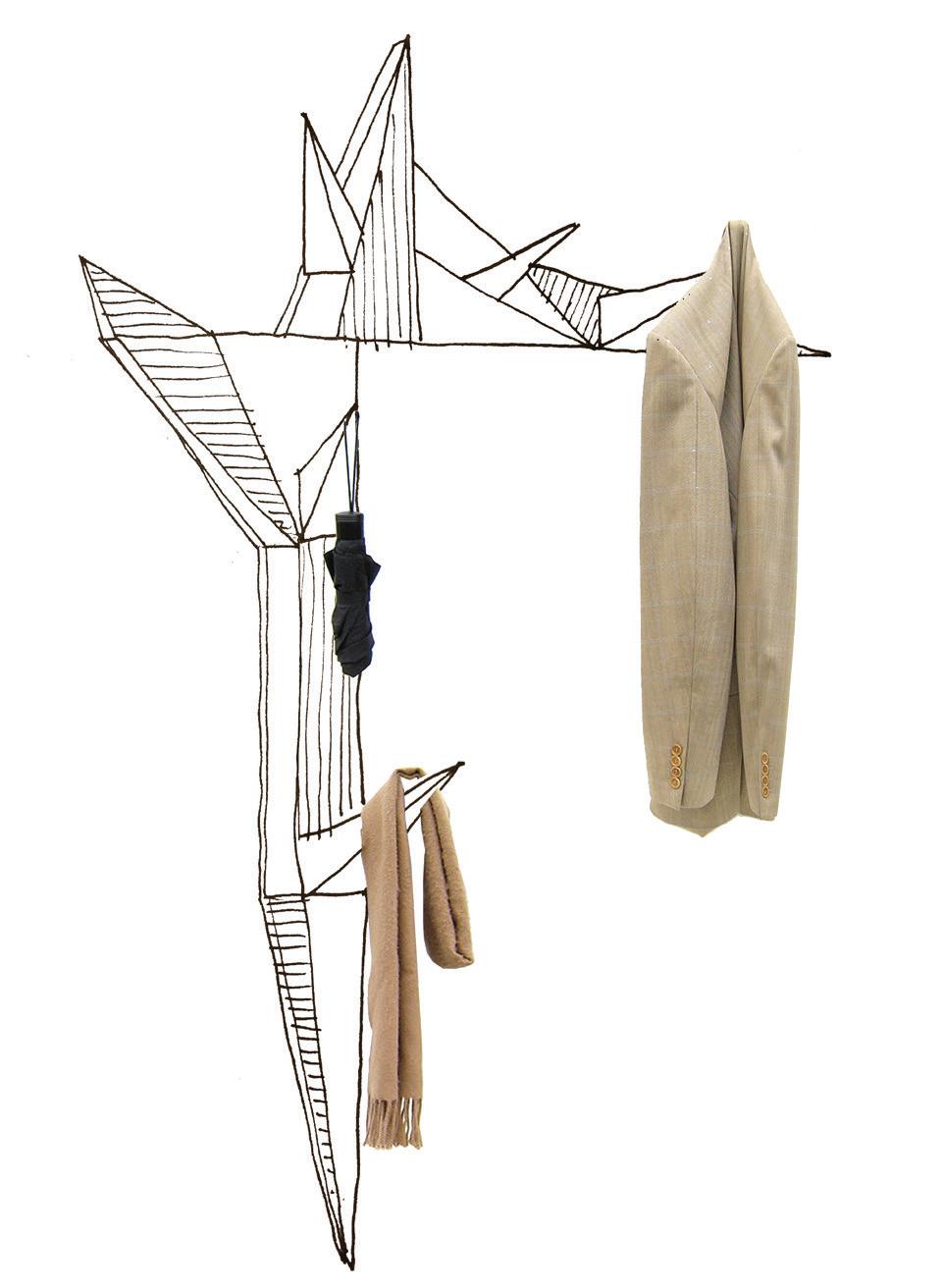
The pointy geometry simulate the appearance of spikes which are meant to be slightly intimidating so that it will raise people’s awareness.
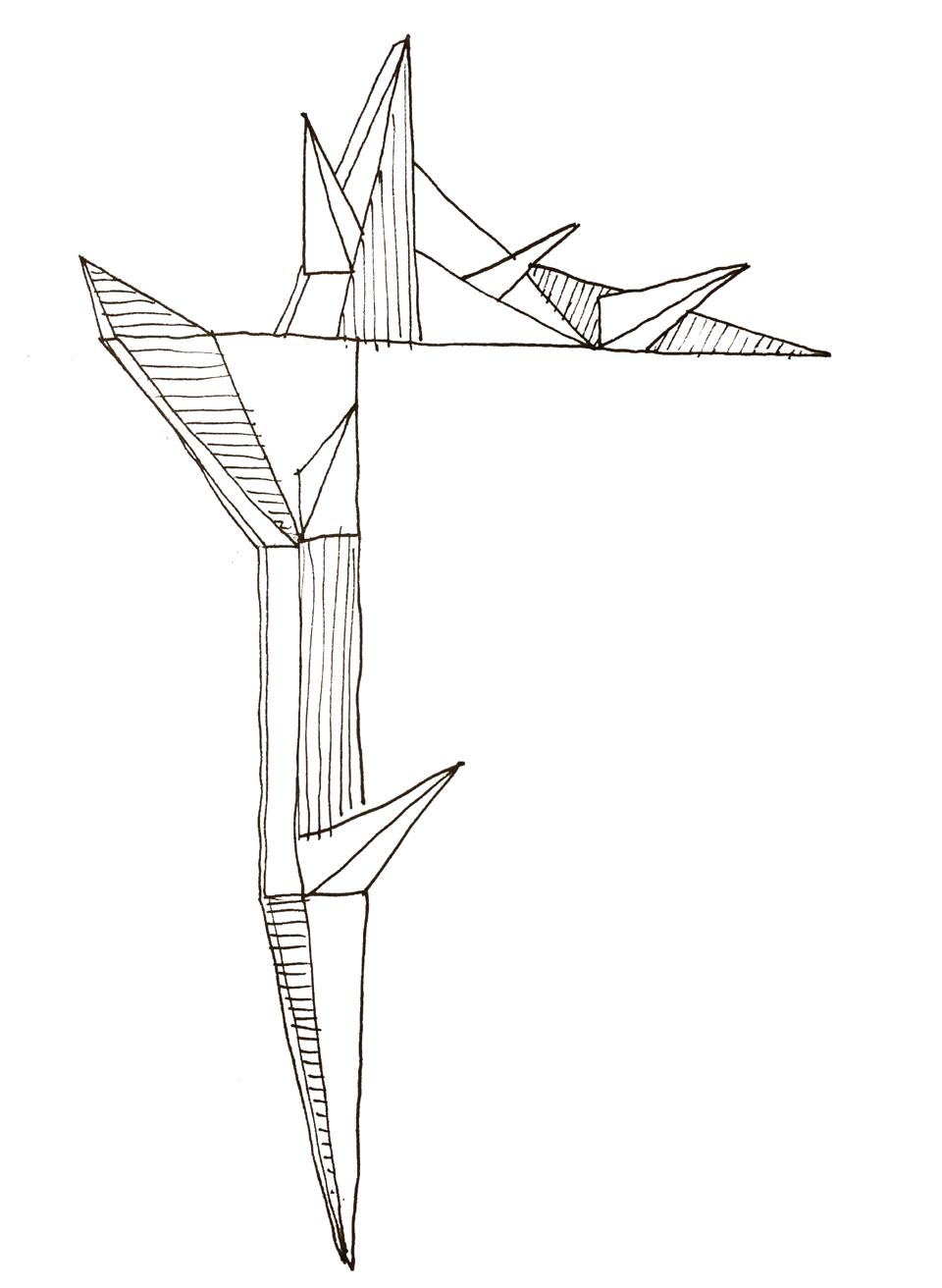
FINAL DESIGN
Tool paths - Round 1
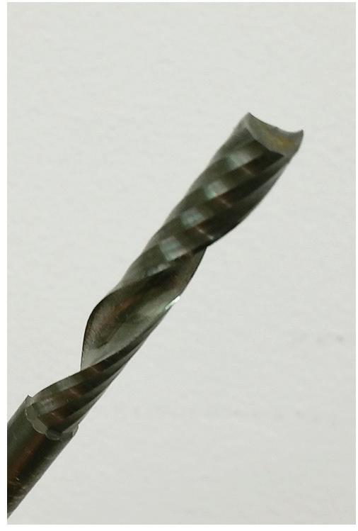
6mm Up Cut Ninja End Mill
Note:
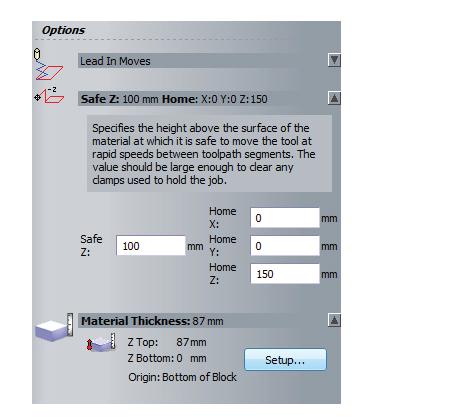
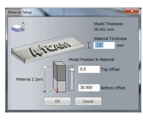
F22- Measure Tools Height
F55- XY ---> SET
Wood Location on Bed
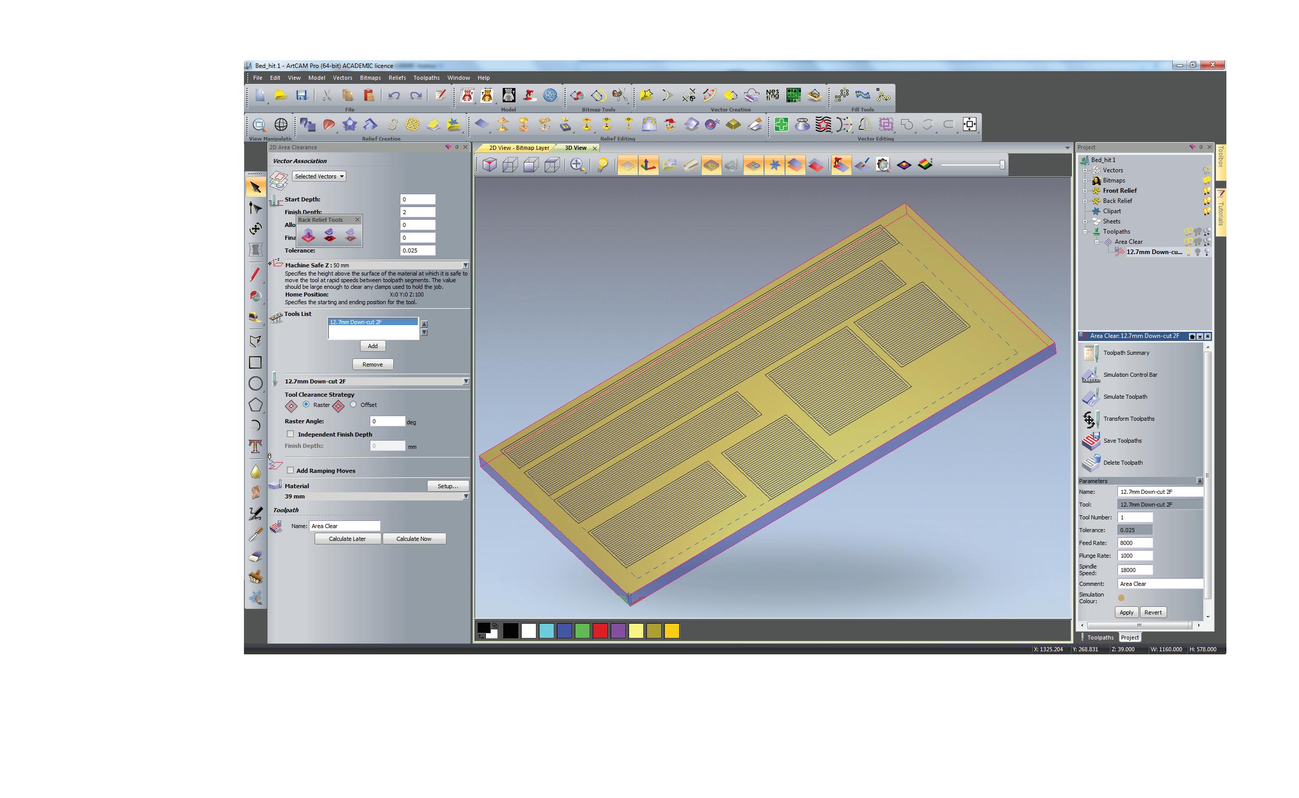
2D Area Clearance
6mm Up Cut Ninja End Mill
FINAL DESIGN
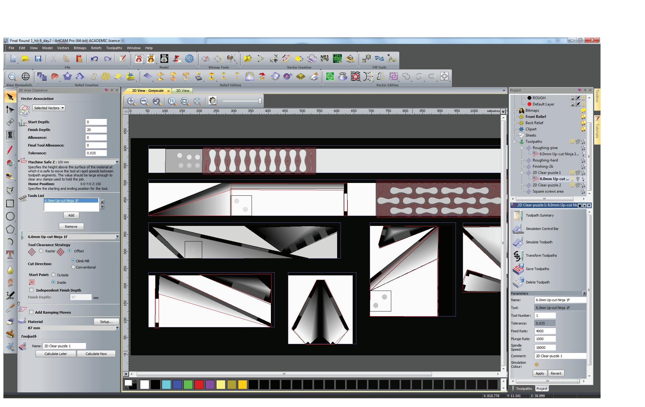
Tool paths - Round 1
2D Area Clearance
6mm Up Cut Ninja End Mill

FINAL DESIGN
Tool paths - Round 1
3D Roughing
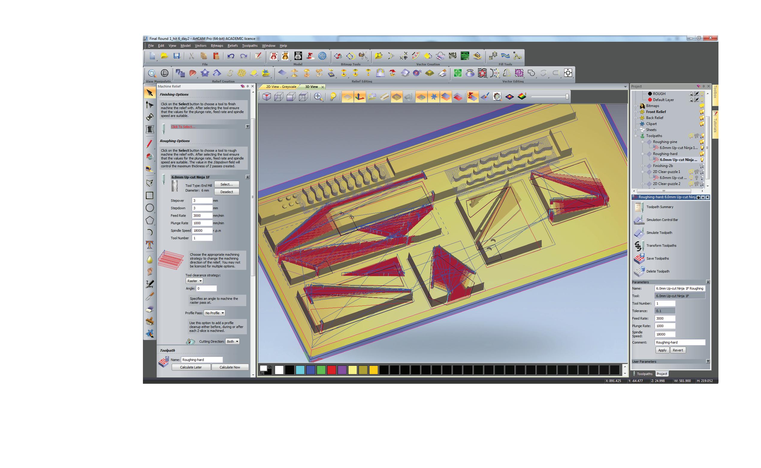
6mm Up Cut Ninja End Mill

FINAL DESIGN
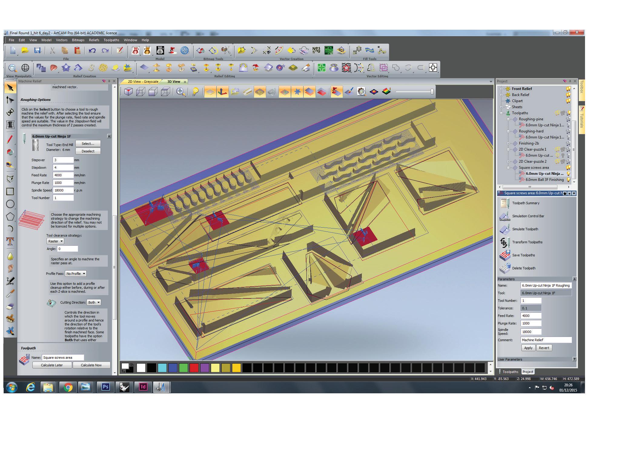
Tool paths - Round 1
Roughing (Raster)
6mm Up Cut Ninja End Mill
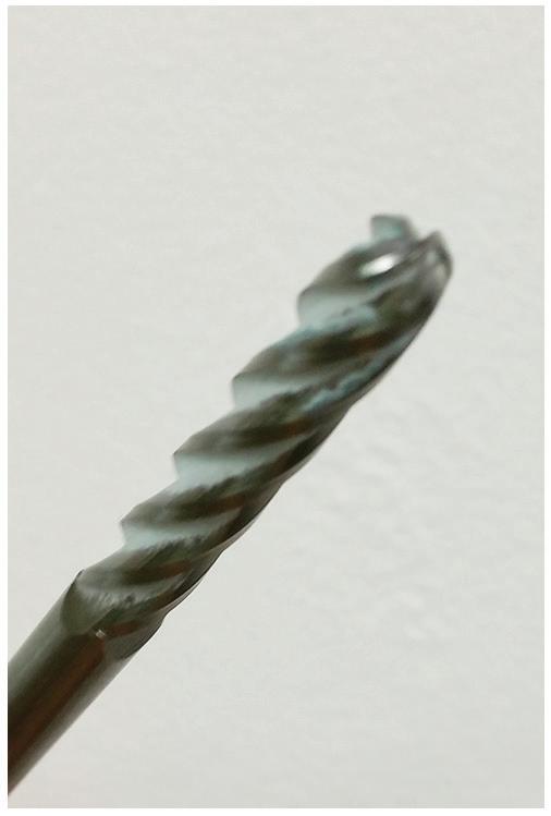
Finishing (Offset)
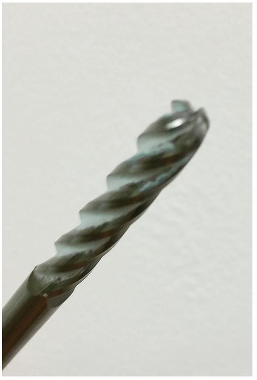
6mm Up Ball Nose 3F

FINAL DESIGN
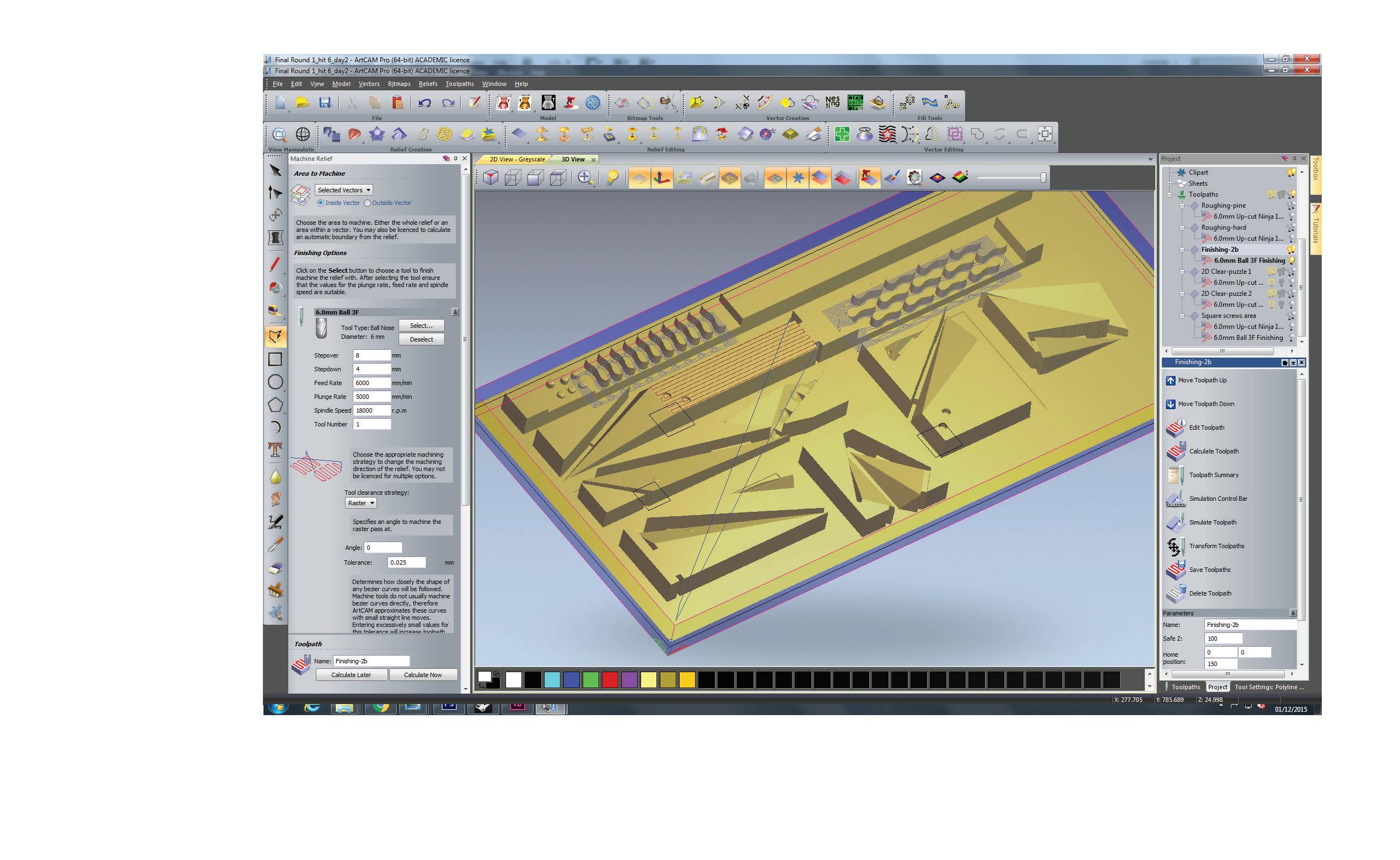
Tool paths - Round 1
Finishing (Stepover 8mm)
6mm Up Ball Nose 3F

FINAL DESIGN
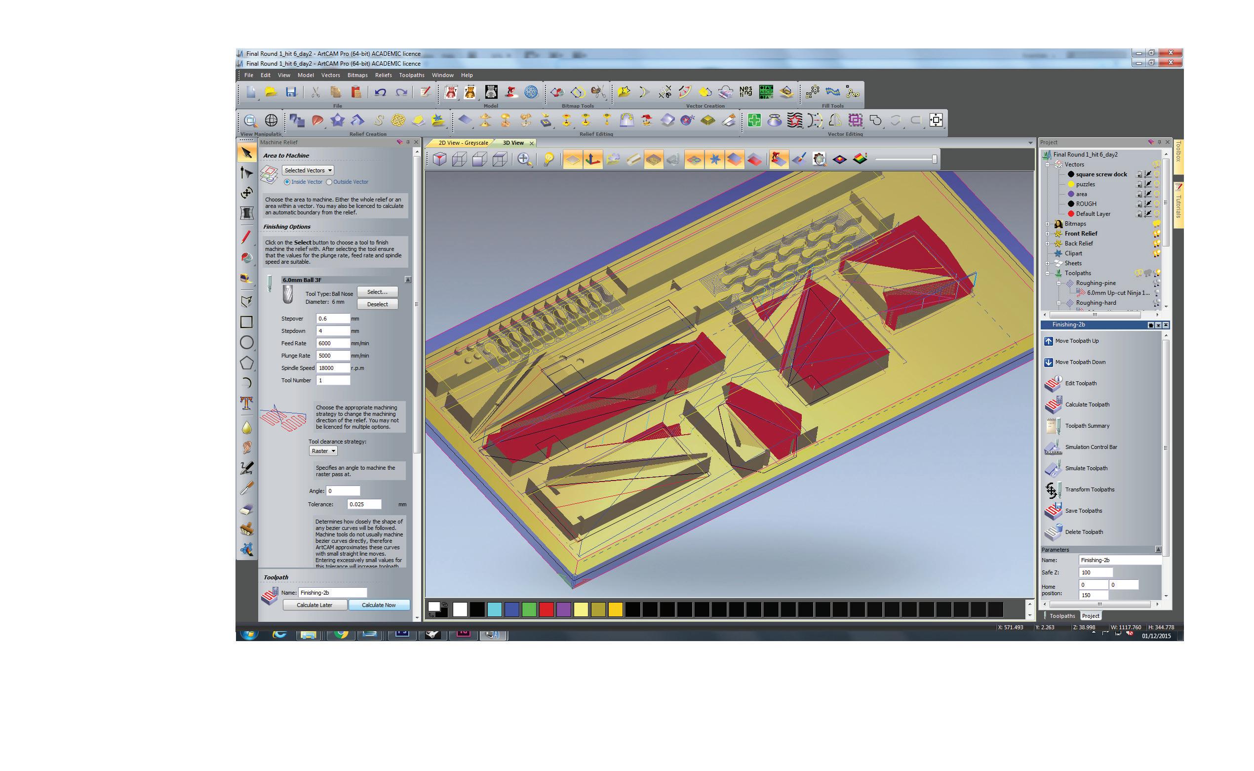
Tool paths - Round 1
Smooth Finishing (Stepover 0.6mm)
6mm Up Ball Nose 3F
FINAL DESIGN
Tool paths - Round 2
3D Roughing

6mm Up Cut Ninja End Mill

FINAL DESIGN

Tool paths - Round 2
3D Roughing (Stepover 4mm) 6mm Up Cut Ninja End Mill

FINAL DESIGN
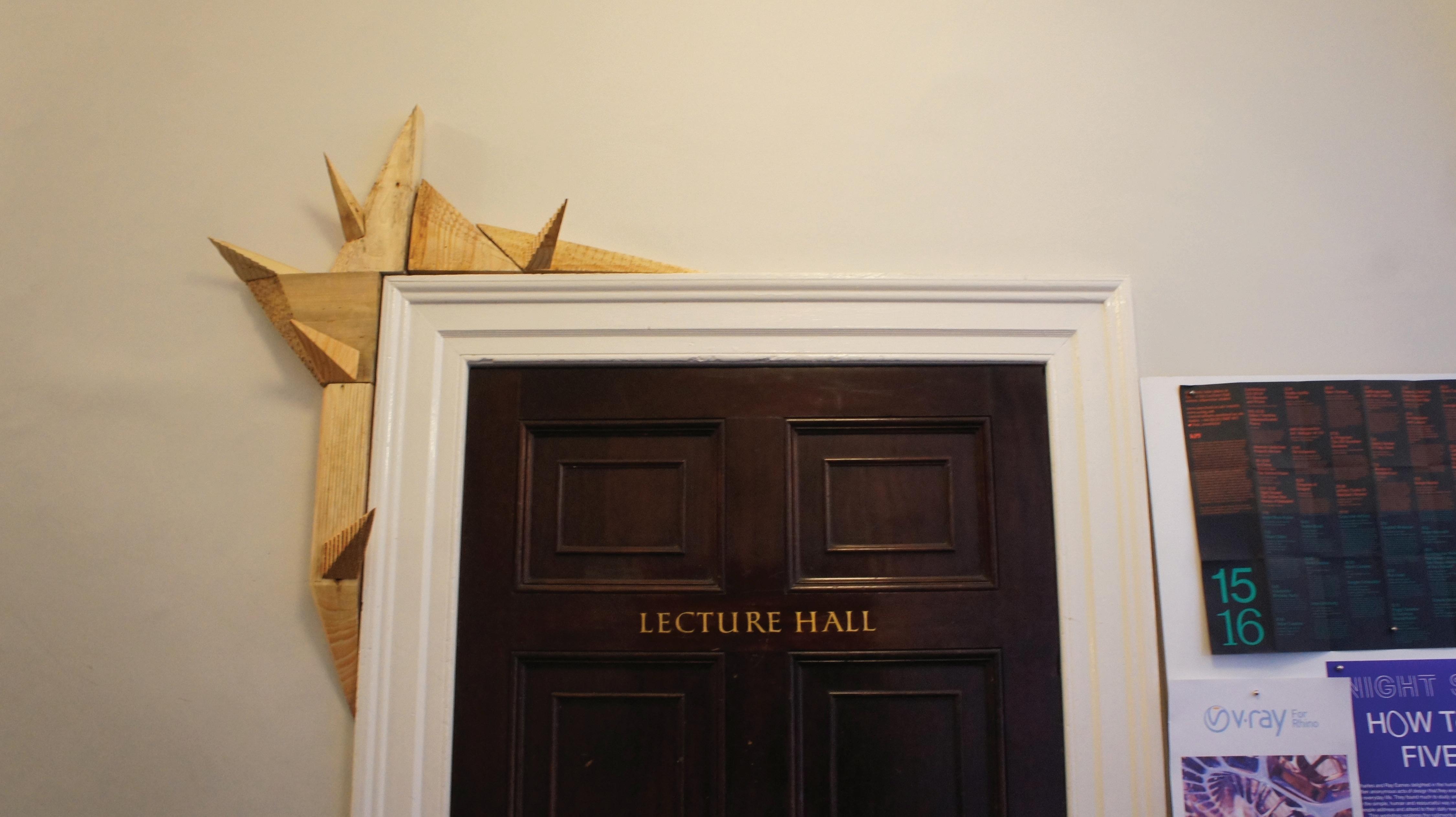
Installation on Site
FINAL DESIGN
Installation on Site
FINAL DESIGN
Installation on Site
FINAL DESIGN
Installation on Site
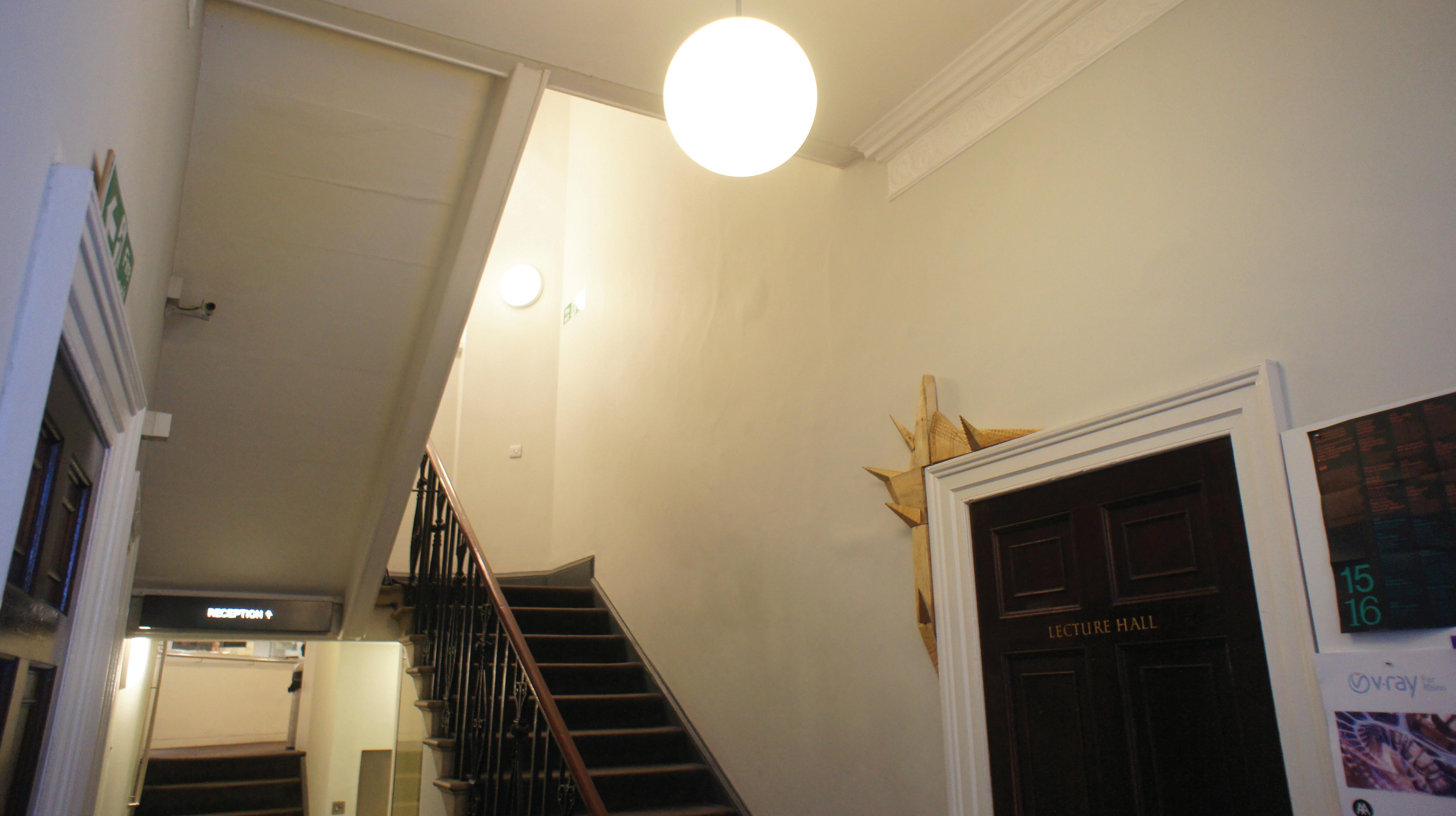
FINAL DESIGN
Installation on Site
FINAL DESIGN Self-Evaluation
Overall, it has been a good exercise to learn the tool and achieve an installation. For it is common for us to practice design but not so much in realizing our design, and being able to do that help me understand more the logistic issues in bringing the design into reality in which it informs the ultimate design too.
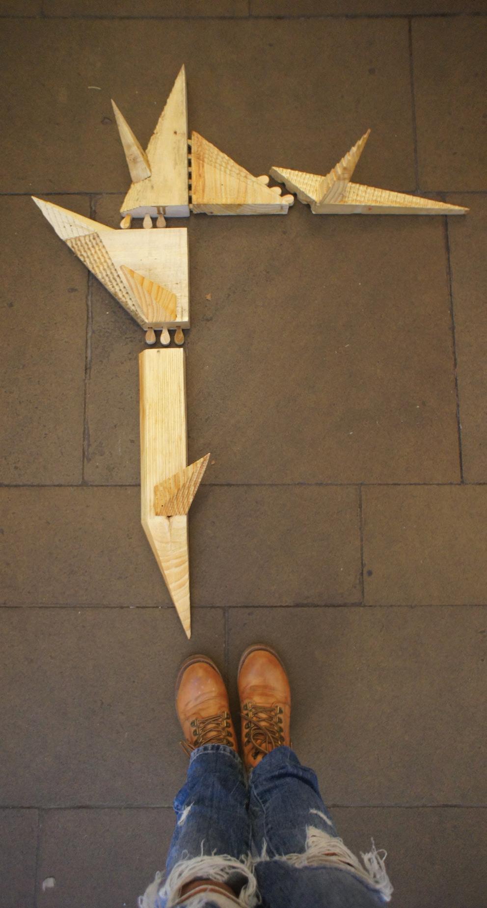
It was extremely difficult for me to master the use of CNC, mainly due to my piece has a lots of conjunction where precision is required. I realise in order to do something really perfect, I need to be really precise myself, from 3D modelling to setting up the jig and the wood piece preparation itself.
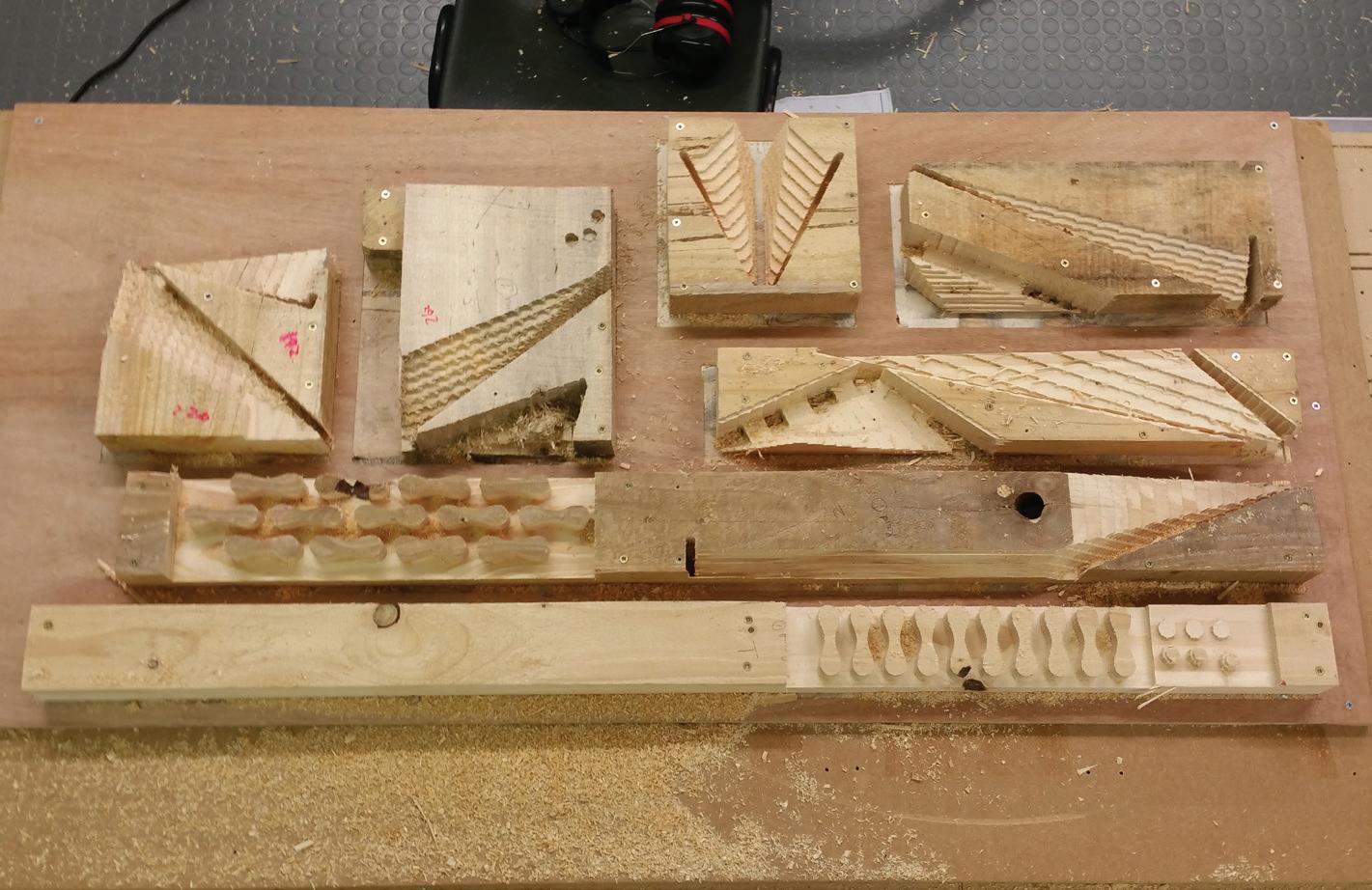
It was also relatively more difficult as I am modelling with scraps, which are not prepared for CNC so I need to prepared them by removing the wood knots and adjust my 3D so it the CNC will avoid area where the existing screws are. Another challenge is that, when I am trying to do double sided CNC I need to put an extra bed to locate them, hence I need to screw them onto the bed, as the machine cannot vacuum the pieces. And since I am trying to maximise the size of each component I have to get the location of screws carefully. As an outcome, I managed to cut the scraps avoiding all the screws and maximise each piece without destroying any tool. However, it was still extremely risky and I would not recommend anyone to try the same method...
The joinery are then machined out to put the piece together, and despite some sanding still required, it is much more manageable than previous ones. The tolerance I used was 0.5mm.

