18 minute read
What the voids have in store

from Immerse 2018

What the voids have in store by H.V. Ragavendra
What makes the star-studded night sky serve as a cue for pure curiosity and trigger a subsequent train of philosophical thoughts? Well, the appeal of a starry night are the stars of course, you may say. But do you know that the voids that seem like a humble background are as interesting as the stars themselves? While the stellar objects usually steal the show in public discussions of science, Dr. Aravind, researcher of the composition and dynamics of molecules of the Interstellar Medium (ISM), raises the curtain on the play of atoms and molecules that are largely in the dark, well, literally.
Advertisement
Dr. Aravind and his research scholars, who form the group of Atomic and Molecular Physics in Physics Department at IITM, have been actively studying in their lab, the nature and behaviour of molecules that are found in the vacant spaces between stars. The Interstellar Medium usually contains highly energetic protons, electrons, electromagnetic waves and multiatomic anions. These negatively charged anions made of several elements are the ones that give us information about the voids, like how sparse they are and what chemical reactions one can expect to occur amongst them.
The usual method to test the presence of a molecule or an ion in ISM is to measure the wavelength of the light emitted by it in the lab and compare it against the wavelength recorded from astronomical observations. If the molecule emits light same as the observed ones, one can go ahead and study how it reacts in such an environment. This method is called ‘laboratory astrophysics’, where you simulate astrophysical environment; put in the molecules that are likely to be present in actual astrophysical environments and see what the reactions and end products are in the simulated one. The professor and his team address two crucial aspects of this study. The first is to identify the structure and energy levels of the constituents of ISM and the other is to study their dynamics by identifying the reactions between them. They employ a variety of techniques to perform these two studies.
The first hurdle in the studies of anions is their synthesis. Neutral molecules are happy the way they are and allergic to negativity, that is, they do not easily accept another electron and become anions. Even when ionized, the anions easily break apart when excited. One way to make neutral ones pick up electrons is to let them expand faster than the speed of sound in a vacuum chamber, which is evacuated to a pressure of around 1 part in 100 million of normal atmospheric pressure, and hence get cooled. This is called ‘supersonic cooling’. This cool gas is subjected to high voltage electrical bursts. This makes the molecules pick up electrons and turn into negative ions. The idea of cooling before ionizing makes sure the ions do not get agitated and break apart. But there is variety in the anions produced; so we must select the ones we want from this collection.
This business of selecting the desired type of anions is taken care of by a crafty device called ‘Time-of-Flight-mass spectrometer’. This works on the principle that for a given force, heavier ions move
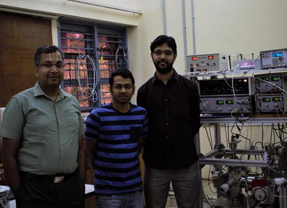
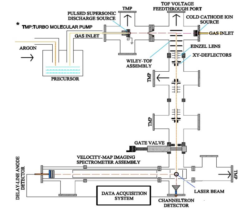
Dr.G.Aravind and his students: Saroj Kumar Barik and Roby Chacko Fig.1: Schematic of PES setup complete with Mass-time spectrometer and VMI. The PES, which forms the top part of the figure, works like this: The ion source, the repelling electrode and mass-gate are supplied with electric potential in the form of a train of pulses. The ion source containing supersonic cooler and an array of cathodes produce anions in bunches corresponding to voltage pulses. The repeller whose pulses are delayed with respect to the source pushes the anions through the time of flight chamber. The mass-gate whose pulses are further delayed traps the required anions. The delay of the massgate with respect to the repeller is the one that selects the desired mass from the variety produced. All these delays are within one pulse range, such that the entire sequence is repeated for each pulse and a steady supply of anions is achieved.
This means that if you know the mass of a particular anion you know the time it takes to fly across a given length. So, different masses arrive at different times at a particular point in the detector. To be exact, the time of flight of anions with 1 unit negative charge, is proportional to the square root of their masses. That means, if it were twice massive, it will be 4 times slower; thrice massive, 9 times slower. Hence the spectrometer is tuned to let the unwanted masses to fly off and when the ion of required mass comes, a mass-gate made of meshes with electric voltage is turned on to trap it. All this happens in nanosecond scale (a nanosecond is one part in a billion divisions of a second) as the device can be precise enough to identify anions arriving by delays as small as eight nanoseconds.
With the required anions produced and filtered thus, the research group proceeds to study the energy levels of the anions. For this, photons of suitable energy are made to hit anions and kick out the extra electron from it. Quantum mechanics dictates that the anion’s energy is quantized, that is, it can only have certain energy values, not arbitrary ones. So, knowing the photon energy and by measuring the electron’s kinetic energy, we should be able to say what the energy levels of the anions are. Most of the anions have utmost one electronic state that is stable against electron detachment. The excited states of anions eventually detach an electron or dissociate into neutral and negative fragments. Such excited states, called ‘resonances’, play a vital role in Astrochemistry, as they influence the way a molecule fragments. These resonances provide insights to the population of molecular species in the ISM, as we shall see, in one of their recent study. Note that we start with neutral molecules first, ionize them, then kick the electron out and study it to understand the anion. In a sense, the electron acts as the messenger that is deployed to collect information about the anion it was made part of. This technique of inferring energy levels of anions using electrons kicked out by photons is called Photoelectron Spectroscopy (PES). So much to get a single number, the energy of the electron? Well, there is more. It would be better if we get the velocities (both speed and direction) of the electrons emitted from a group of our anions, not just their kinetic energy. This idea of velocity mapping is the state-of-art technique for studying anions.
The professor reminisces building a Velocity Map Imaging device (VMI) for anions, during his days of Ph.D., which happened to be the first of its kind in India. “The process of velocity mapping, even for anions, is extremely tricky. But doing the same for electrons brings in its own host of problems”, he says, regarding his pursuit of this particular study ever since. To device a VMI setup for electrons, one has to exclude all possible external fields, even the feeble ones like Earth’s own magnetic field and those from materials like screws and bolts in their vicinity. This is because these are enough to deflect particles as light as electrons from the expected trajectory. So the chamber covering the path of electrons has to be shielded with -metal (an alloy of Nickel and Iron), which can shield almost all the stray magnetic field. There are several such precautionary measures to be taken and sensitive fine-tuning to be done to achieve VMI of electrons. Such a delicate yet indigenous construction that is currently hosted in this lab, has been a real achievement for the group. This full setup of PES, i.e., VMI combined with Mass Spectrometer, as shown in Figure 1 is for electrons emitted by anions when impinged with laser light. To put the working of the device in simple terms, it has electric field lines configured in a specific shape in space such that when electrons pass through them, they get pushed according to their speed and direction of motion. In a sense, the field categorizes the electrons going through them as per their velocities before they hit the screen. This results in electrons of a given
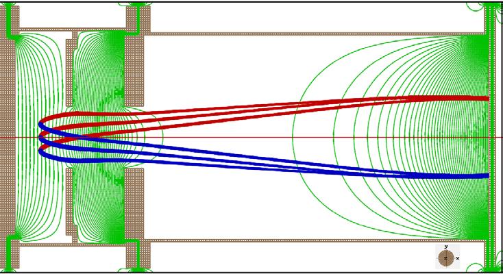
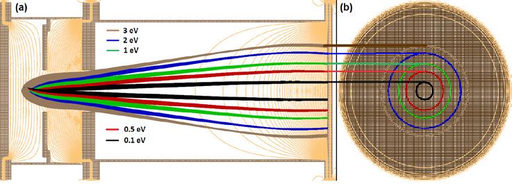
Fig. 2: (Top) Electric field configuration in Velocity Map Imaging setup Fig. 3: (Bottom left) Electrons of given energy having a unique trajectory. (Bottom right) Detector screen with rings corresponding to trajectories
speed and velocity direction falling at a particular point on the detector screen. This configuration is illustrated in Figure 2, where the green lines are field lines and the blue and red lines are the paths of electrons with the same speed but opposite orientation. This means that if you know the point in the screen where the electron has hit, you know its speed and the angle it made when it hit the laser. This at the end of the run, presents a visualization of the vector field of the velocities of electrons in the screen. Of course, since the screen is two dimensional, we get the 2D picture or a projection of the vector field. A typical detector screen at the end of the run will look like Figure 3.
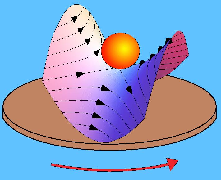
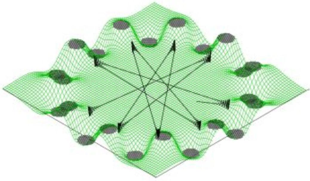
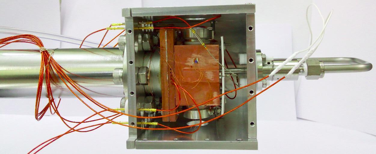
Figure 4: Effective potential of a 4-pole ion trap Here, the electrons recorded in a given ring correspond to the same speed and hence the same energy. The radius of a ring is proportional to the speed of electrons forming it; larger the ring, higher the speed. A point on the ring gives the angle the velocity vector makes with the laser axis. This visual depiction of the velocity field of the electrons, on further analysis, gives the complete information about the state of the anion. The interesting aspect is that because of the time scale and precision of the instrument described, the production of ions and the velocity imaging of electrons is done in a single run of the experiment. Understanding the composition and energy levels of anions is just one part of the group’s aim. The second phase is to discern the dynamics of these anions: how they react chemically amongst themselves and what products they give out. For this purpose, the team has indigenously built ‘ion trap’. Ion traps, in general, are considered a boon for spectroscopic analysis because they do what is usually considered very difficult and therefore circumvented in most studies - they hold the anions in a reasonably small volume. With no demand for any increase in timing precision or indirect studies, one can put the anions inside an ion trap, cool them and see them react with the environment you design. But it is almost impossible to keep a charge at rest using an electric field. They are easily attracted or repelled out of their position by other charges or forces in their vicinity. Well, then how does this trap “trap” ions? The schematic, given in Figure 4, shows how it works. The rods are supplied with an electric potential that varies with time periodically, in such a fashion that alternative rods have a constant offset in their potential at any time, which effectively places the ion in a rotating saddle as shown. In simple terms, when the negative charge sees positive potential in a rod and moves towards it, the potential is switched to the next rod. This makes the charge to change its direction and by the time the change occurs, it is again switched to the subsequent rod. By timing this sequence precisely, the charge is effectively trapped in a region around the center of the cylindrical chamber. This tantalizing application of electric potential - the pushing and pulling of the poor ion towards a different rod at subsequent instances so that the net displacement of it is zero, gives us the time required to conduct experiments on it. The ion trap, as depicted here in Figure 5, has twenty-two rods and again one of its kind in the country. It produces an effective potential as shown in Figure 6. This trap, loaded with the candidate species (usually a Polyaromatic Hydrocarbon), is to be cooled to around 4 Kelvin, using liquid Helium, which is the typical range of temperatures of ISM. Then, it can be made to react with other species of candidate gases and the products formed are checked at different time scales. The products when identified with a mass spectrometer will tell us about the probability of their occurrence in ISM. They
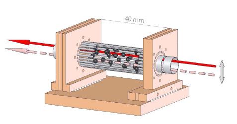
also tell us the typical time taken for a reaction to occur at these extraordinary environments compared to the usual rate of reaction in lab conditions. This setup is being equipped with sensors and after calibration, it will be employed to study Fullerene cation (C60+), a species of molecules which is found to be abundant in ISM recently.
Such studies of reactions between different candidate species are exciting and as they sometimes suggest the presence of unexpected species of molecules or ions in space. They also help solve the mysterious presence of some rare anions in interstellar voids, whose formation mechanisms are subjects of interesting debates. In addition, they may provide an alternative explanation to the existence of species that were hitherto known to be of different origin. One such instance is the explanation for the abundance of CN- in ISM. So far, they were known to be formed in the extremely hot shock waves following supernovae explosions that mark the end of giant stars. But, Dr. Aravind and his Ph.D. student Roby Chacko, say that they have witnessed an exciting result concerning formation of CN- through an alternative and relatively cooler mechanism - through the dissociation of one of the heavy molecules in its ionized and unstable, excited state (recall the resonance states described earlier), at temperatures much lower than that of supernovae. Such new physics is what typically motivates further pursuit of this work. One can never know what exactly happens in such strange environments that we are probing.
The future outlook for this project will be the assembling of a full-fledged apparatus of anion analysis in a series of Ion Source - Mass spectrometer - Ion trap - Mass spectrometer. A setup of this design will at once produce anions, mass-select the required species with the first mass spectrometer, trap the selected anions and make them react with a supplied environment and identify the products coming out with the second mass spectrometer. A desirable extension to this setup will be ion benders placed on either end. This will enable placing a laser source along the assembled line of spectrometertrap-spectrometer that will open the doors to study ionphoton interaction along with ion-neutral and ion-ion interaction. This addition may not take long, as the ion bender has already been devised by one of the project students of the lab. Such an environment of simultaneous development of apparatuses and sequential conducting of experiments through different projects, yet with a common objective and a clear coordination among them, makes sure the members of the lab know their part in the larger picture to contribute efficiently.
Figure 6: Effective potential of a 22-pole ion trap. The black lines mark the possible trajectory of an ion. Fig. 7: Picture of the Ion-trap in the lab, attached with different sensors
“That is the thing about the students”, says Dr. Aravind indulgently, “They have the potential to do good quality research; it is just a matter of showing them the right direction”. This is evidenced by the number of devices populating the lab in different stages of their building and assembly. These stand as souvenirs of the patience and perseverance demanded by such works of ambitious nature. “For instance, the calibration of the instruments like mass spectrometer
alone can take up to two months”, says Roby Chacko, signifying the time involved to assemble, test and run the devices developed by them. Accuracy and consistency of the results are of paramount importance. However, from what Roby says, there is always a thrill in this research of discovering a new phenomenon or materializing something that was completely speculative. And this is what, we gather, drives Dr. Aravind’s group in their quest to decrypt the darkness of the night sky.
H.V. Ragavendra (Author) H.V. Ragavendra is a research scholar working on Cosmology in the Department of Physics, IITM. When his to-do list looks sparse, he tries to expand yet catch up with his to-read list that may contain anything from scientific review articles to a Poetic thriller or a dystopian novel.
Dr. G. Aravind is an Associate Professor in the Department of Physics at IIT Madras. He did his B.E.(Hons) in E.E.E and M.Sc.(Hons) in Physics from BITS Pilani in 2001. He then did his PhD in experimental atomic and molecular Physics at the Tata Institute of Fundamental Research (TIFR) Mumbai. He worked as postdoctoral fellow at the University of Aarhus, Denmark, in the Department of Physics and Astronomy and then in the University of Basel, Switzerland. His research interests include photoelectron spectroscopy and dissociation dynamics of Interstellar medium ions. He was awarded the INSA Young Scientist Medal for Physics in 2012 and Young Faculty Recognition Award in 2017.
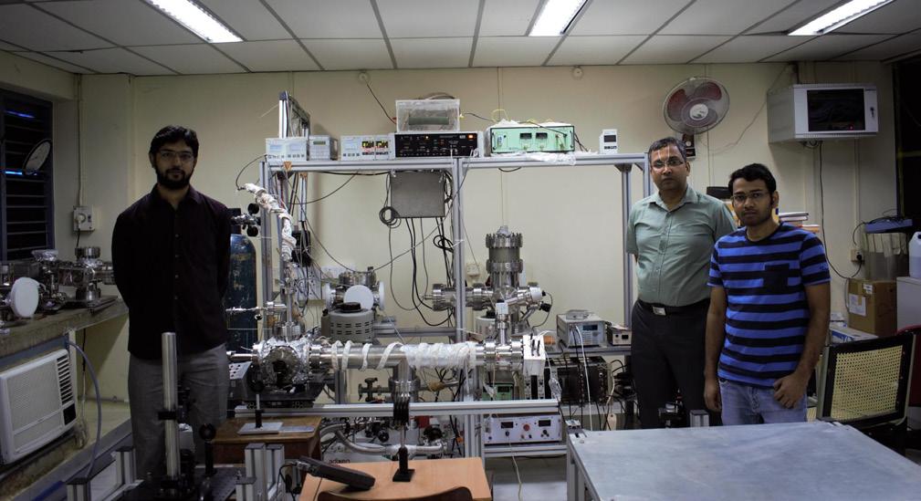
The research group with their Ion-trap-Mass-spectrometer setup
Citations
Aerospace Engineering
1. Cover image: Chaotic flow-field by Chandan Bose. 2. Double pendulum schematic by Catslash - Own work,
Public Domain. 3. Double pendulum long exposure shot by George
Ioannidis - Own work, CC BY 3.0. 4. Flapping wing micro air vehicles by Chandan Bose. 5. Domestic pigeon flock. By Toby Hudson - Own work, CC BY-SA 3.0. 6. Vorticity contours from Identifying the route to chaos in the flow past a flapping airfoil by S. Badrinath,
C. Bose, and S. Sarkar, European Journal of
Mechanics/B Fluids 66 (2017) 38-59.
Applied Mechanics
1. Cover image. By Bernal Saborio from Costa Rica -
A340-600, CC BY-SA 2.0. 2. Intermittent time series by Malayaja Chutani. 3. Aircraft showing wing flutter. From https://www.dgflugzeugbau.de/wp-content/uploads/dg-300-flattern. jpg 4. Experimental results showing plunge response of airfoil from: Precursors to flutter instability by an intermittency route: A model free approach, by J.
Venkatramani, V. Nair, R.I. Sujith, S. Gupta, and S.
Sarkar, Journal of Fluids and Structures 61 (2016) 376–391. 5. Numerical results showing plunge response of airfoil from: Physical mechanism of intermittency route to aeroelastic flutter by J. Venkatramani, S. Krishna
Kumar, S. Sarkar, and S. Gupta,Journal of Fluids and
Structures 75 (2017) 9–26 6. Recurrence plot. By Pucicu at English Wikipedia, CC
BY-SA 3.0.

Biotechnology
1. Cover Credits: http://www.uab.edu/medicine/cnc/ images/M_images/wow_brain.png 2. NGS transcriptome data analysis at a glance: finding out the real cause of neurodegenerative disorders. Source:
Diagram by author, created using Adobe Illustrator (AI). Line drawing of brain, from pixabay.com, modified using AI. Neuron-glia communication image from Wikimedia Commons (OpenStax CNX Biology textbook).
Civil Engineering
1. Figure 1: International Water Management
Institute (IWMI). Water for Food, Water for Life: A
Comprehensive Assessment of Water Management in
Agriculture; Earthscan: London, UK, 2007. 2. Figures 2-7: Prof.Ligy Philip and lab
1. Figure 1: Control Architecture : Subhadeep Kumar,
Nirav Bhatt, Ramkrishna Pasumarthy, A Novel
Vehicle Model for Longitudinal Model Analysis,
Mediterranean Conference on Control and
Automation (MED), July 2017 2. Group Photograph
Chemical Engineering Chemistry
Credits for all figures: Prof.Kothandaraman Ramanujam and lab
Credits for all figures: Dr. Shankar Ram and lab.
Credits for all figures: All figures are due to Healthcare Technology Innovation Centre, IITM Research Park.
1. Cover image. By DeTect Technologies 2. Corroded pipe. By Dhvani Research. 3. Example of non-invasive testing. By Dhvani Research. 4. Group photograph. By Prof Krishnan
Balasubramaniam.
1. Figure 1 : A ‘Phase Diagram’ analogy for food. Credits : Guruvidyathri. 2. Figure 2 : Understanding Gibbs Energy. Credits :
Schroeder, Daniel V. An introduction to thermal physics. San Francisco, CA: Addison Wesley, 1999. 3. Figure 3 : Flow of information in the CALPHAD method. Credits: Soumya Sridar 4. Figure 4 : Comparison of calculated Zr-N phase diagram and experimental data. Credits : Prof. Hari
1. Image of Ion trap: Photodetachment of Cold OH− in a Multipole Ion Trap” by S.Trippel, et.al., (doi 10.1103/PhysRevLett.97.193003) 2. Images of Rotating Saddle : Dr. Jessie Petricka’s webpage ( http://physics.gac.edu/~petricka/research/
General%20Concept.htm ) 3. and Dr. Holger Kreckel’s webpage ( http://www. hkreckel.de/ion_trap.html ) 4. Credits for remaining figures: Dr. Aravind and lab.
Engineering Design
Electrical Engineering
Mechanical Engineering
Materials Engineering
Physics
Thanks
for Reading.
Readers of Immerse comprises the students and faculty members of IITs, IISERs, and NITs, apart from the online audience, of course. If you are a student at IIT Madras and would like your research project to be featured, we would be delighted to hear from you. Email us at immerse.iitm@gmail.com.
If you found this issue exciting and would like to contribute next time, be it as an editor, writer, photographer or graphic designer, please get in touch with us at the same email address. We will let you know how you can contribute.
If you liked our magazine, please do visit our websites to view our previous editions and several exciting articles featuring the research going on in IIT Madras here: www.t5eiitm.org/immerse
In any case, if you have anything to say, be it praise or criticism, we welcome your views. Let us know by filling this feedback form https://goo.gl/forms/mkp9uZXyitLnDI652, also accessible via this QR code.