5 minute read
Getrag Gearbox Rebuild
Getrag Gearbox
REPAIR THANKS TO Stephen A Brear Gearboxes 0113 263 2073 www.stephenbrear gearboxes.co.uk
Advertisement
Mad4mini
PART TWO: 0113 276 1636 www.mad4mini.co.uk
Rob Hawkins
discovers there are more problems to fix on the Getrag gearbox for a 2005 MINI, but luckily, a local specialist can save the day with some machine work and new bearings.
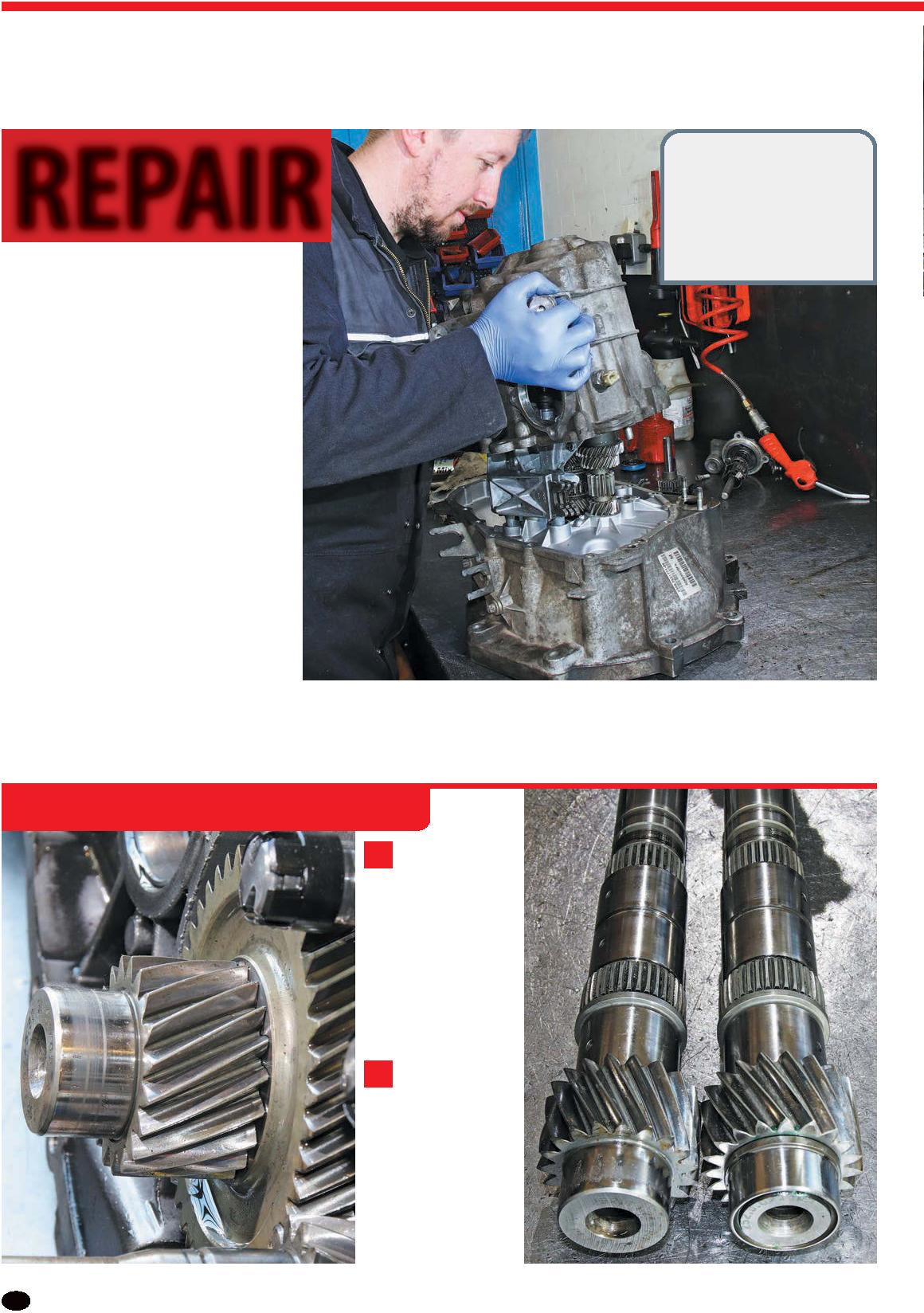
It’s bewildering to think that replacement parts for a gearbox from a vehicle that was manufactured less than 20 years ago are no longer available, but when it comes to the Getrag manual ’box for the later R50 MINI One (early models had a Midlands gearbox), some parts are no longer available. Fortunately, most bearings are a common size, so they are readily available, but when we discovered the end of the main shaft inside our gearbox had worn and needed replacing, new ones are no longer available. Luckily, the gearbox specialist we visited, who generally only deals with the trade, had a solution. They proposed machining the end of the main shaft, fitting a sleeve and then reassembling the gearbox with a suitable new bearing for it.
The following steps show the damage we found inside our Getrag gearbox, how it was fixed and the reassembly of the gearbox.
ASSEMBLING THE GEARBOX
1 We took our Getrag gearbox to
transmission specialist Stephen A Brear Gearboxes where they immediately noticed the wear on the main shaft and explained this is probably the cause of the excessive noise. Plus, it’s only a matter of time before this will fail.
2 Brear’s solution to such a common
problem is to have the end of the main shaft machined down and sleeved (as shown on the right of this photo – the original shaft is on the left). New parts are not available any more for this gearbox – hence why Brear have modified spare shafts on the shelf.
3 They also inspected the diff bearing and concluded it was worn, so that too would need renewing. In fact, they recommended fitting several new bearings to ensure the gearbox was in good condition.
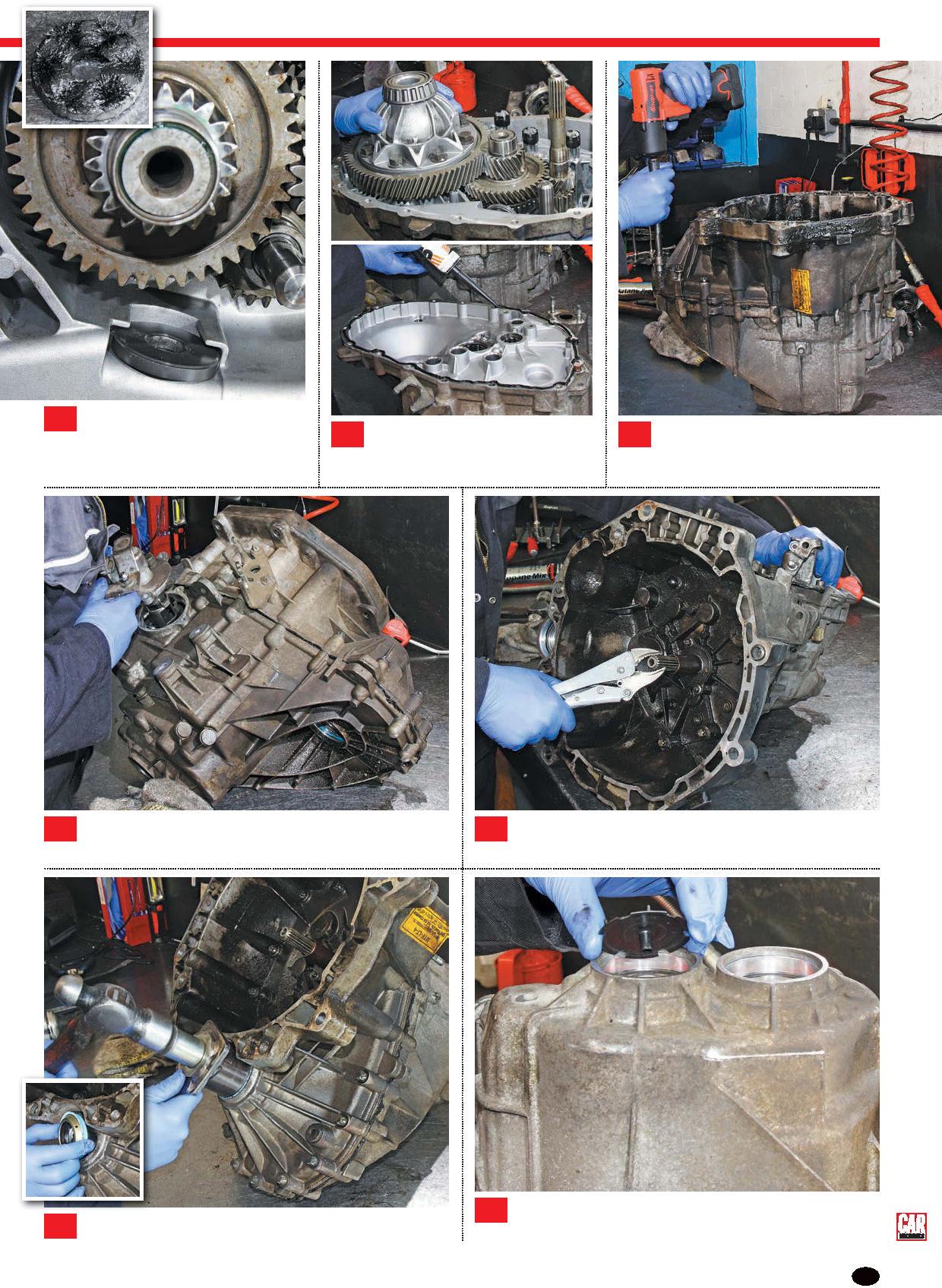
6 Before fitting a new diff bearing race into the offside gearbox casing, John warmed up the alloy with a blowtorch to make it easier to fit. The heat helps the aluminium casing to expand, whereas the steel race is left cold. 4 We joined them after they had stripped out the gearbox, had the main shaft sleeved and were ready to assemble it. Technician John volunteered to complete the job and started with assembling the diff.
5 The new diff bearing was drifted into position using a suitably-sized hollow drift, of which Brears have a varied selection. They’ve also made their own tools or modified existing ones for particular gearbox jobs. 7 John lowered the new bearing race into position, then seated it using a hammer and drift, making sure he fitted it evenly. 8 The diff was trial-fitted and spun to ensure it rotated freely. Then it was removed as more parts were about to be fitted.
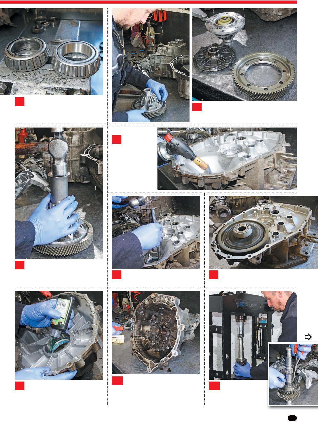
9 Taking the other half of the gearbox casing (the deeper offside section), John fitted another diff bearing race, warming up the alloy first and applying the gearbox specialist’s equivalent of thread lock. 10 The two halves of the gearbox casing were secured together, then John fed a screwdriver through into the differential to test the pre-load on the bearings. A pre-load gauge can be used here, but John has the experience to test it this way. 11 Next, John assembled the gears for the main shaft, some of which need to be press-fitted and others are secured with circlips.
ASSEMBLING THE GEARBOX CONTINUED
12 Taking the offside gearbox casing, John warmed up the sealed recess where the end of the main shaft sits (the opposite end to where the sleeve has been fitted). 13 He then fitted a new bearing into the recess and progressively seated it using a hammer and drift. Notice there’s an oil funnel/guide in the centre of the bearing.
14 The gear cluster and selector forks were assembled on the workbench, then lowered into position on the nearside half of the gearbox casing. 15 John wanted to replace the two bearings in the nearside half of the gearbox casing, which are for the main shaft and the input shaft, so he drifted them out.
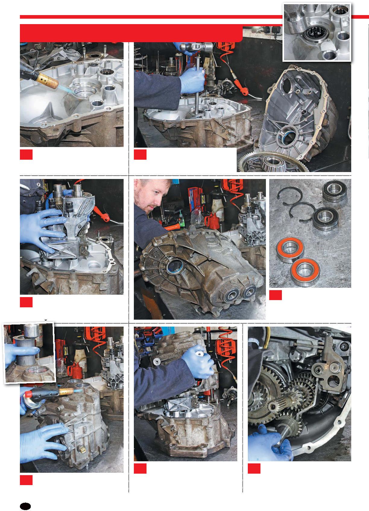
16 After heating up the area where the two bearings sit, he fitted the bearings and drifted them into position. 17 John now trial-fitted the nearside half of the gearbox casing over the gear cluster that was already sat in the offside half of the gearbox casing to check that the two could be fitted together. 18 There were still a few more parts to fit inside the gearbox, so the two halves of the casing were separated, and the reverse idler gear was fitted alongside the gear clusters.
Next, a small magnet was cleaned and refitted inside a slot in the gearbox casing. This collects metal filings with the aim of preventing them damaging the teeth of the gears. John laid the differential in position, then applied a bead of sealant to the mating surface of the offside half of the gearbox casing, avoiding the mounting holes.
19 The two halves of the gearbox casing were joined together for a final time and all 17 of the Torx E12 bolts were progressively tightened.
20 21
The gearchange mechanism was fitted to the exterior of the gearbox. The ends of the gear linkage cables are attached to this mechanism, which in turn operate the selector forks.
