13 minute read
MTV Offers Solder Paste Testing Solution
from Croll6e
by Thomas Swift
Chrys Shea
Feature Interview by Nolan Johnson
Advertisement
I-CONNECT007
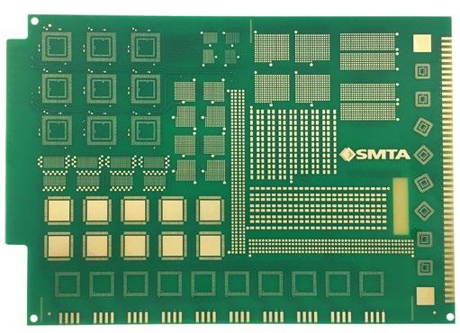
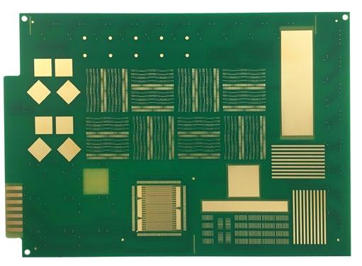
The miniaturization test vehicle (MTV) is a common benchmark test board that can gauge about 25 different paste properties and analyze how different solder pastes will perform in an assembly line. Chrys Shea details the work she’s done to develop and release the MTV.
Nolan Johnson: Chrys, let’s talk about your recent work with the SMTA specifically related to the MTV.
Chrys Shea: The MTV is meant to be a test vehicle that will help qualify new packages and processes for the next at least two to three years, but hopefully longer. We can always spin it if we need to get something smaller than an 0201 metric or a 0.3-millimeter BGA on there, but it’s sufficient to say that it will be solid for a while.
Johnson: What’s the overall purpose of this board and this exercise?
Shea: The original purpose of it was to help people quickly and easily qualify new solder
paste because there’s always a lot of mystery around it and a fear of change; the process chemistry you’re currently using is the devil you know versus taking a risk on the devil you don’t. But every couple of years, solder paste manufacturers come out with better and better formulations. As a consultant, it kills me to go into a place where they need help and find them using a first-generation, lead-free solder paste when there are much better ones out there now. The impetus was to make qualifying a new paste quick, easy, and data-driven.
Johnson: For those who haven’t met you yet, what’s your background? What do you do as a consultant?
Shea: My background is in process engineering. I spent the first eight years of my career on shop floors, either in production or an NPI capacity. Over the next 12 years, I worked for suppliers, helping people on production floors and managing some solder paste R&D and testing labs, and then I struck out on my own as a consultant. Now, I work independently for users or suppliers as need be.
Shea: Soldering. I started out almost 30 years ago wave soldering. I love making solder joints. We do a lot more SMT than wave soldering these days, but I particularly enjoy stencil printing because it merges two of my favorite fields: automation and material science.
Johnson: It seems to me like a test vehicle such as this should have been around a lot earlier. How did this get started? What caused that to happen now?
Shea: What caused it to happen now is that it was an internal test vehicle with Henkel Electronic Materials, and it had a lot of good features on it, so some of their customers were requesting to use it themselves. At that point, Henkel brought me in, we did a first run of it, and we realized we needed to add some intelligence. We had a lot of empty real estate on the board so we could add more features, and we needed to reduce the cost to make it feasible for the general public. We went through that exercise.
This was my favorite project ever and probably the capstone of my career. As we respun this board and added the intelligence, more features, and the embedded DOEs, I drew on things I learned at every job I’ve had in the last 30 years. This was a great project for me. We introduced revision 1, and it had the Henkel logo on it, and the industry wasn’t as accepting as I would’ve hoped. We thought, “We need to make this a test vehicle for everybody,” and I can understand why other companies would not want the Henkel logo in their lab. We talked to SMTA and renamed it the SMTA board, but it is sold through Practical Components. SMTA gets a royalty for every board and kit they sell, and that money goes toward the SMTA education funds. It’s a winwin all the way around.
I’m particularly interested in this because I’ve seen so many different test vehicles. Every large contract shop has a different test vehicle that they’ve done themselves, and a lot of the smaller shops don’t, so they use ones that they can buy online through Practical. Nothing was really modern, and there were no common denominators between them. In other words, I could read a study by Flex and a study by Jabil, but because they’re not using the same test vehicles and the same component footprints, I can’t compare the data apples to apples. As we get more and more users on board with this, we’ll have a lot more of good published data that we can compare.
On the supplier side, I would like to see everybody testing their solder paste on the same test vehicle using the same test method because it will make deciphering supplier data much easier and more straightforward. You might recall when we started checking placement rates with an IPC standard because every supplier had its own tests and metrics. Right now, we have no real standards for print quality that we can adhere to. Everybody tests and publishes their own data on the honor system.


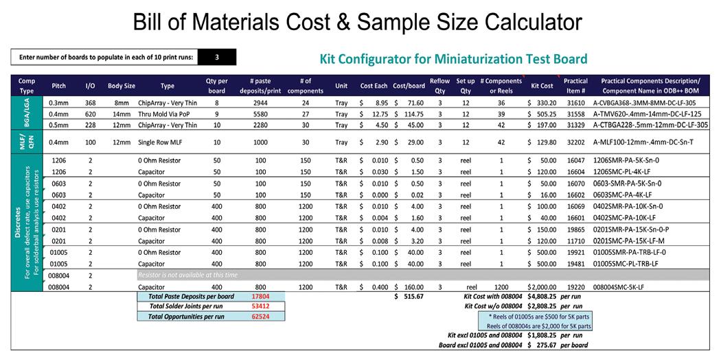
Bill of materials cost and sample size calculator.
Johnson: That makes a common benchmark test board all that more important.
Shea: Exactly. We’re running so much leaner. As we recover from the pandemic, we’re going to have a lot of catch up to do. We don’t have a lot of time to wait.
Johnson: Walk me through how the board gets used then in the field.
Shea: Typically, if you were using this to evaluate a solder paste, you would take this board to run the top side and the bottom side, and we have nested some DOEs in there. The user does 10 prints top side, and populates three of the boards, and then sets that stencil aside and run the bottom side. While the top side stencil and paste are doing an idle time, the user prints five boards on the bottom side and then shears the solder paste on the bottom side for a couple of hours to mimic a regular stencil life test and how it would perform on the assembly line before printing five more. The user reflows some boards, reinstalls the top side stencil, and then runs 10 boards again, to see the impact of idle time on printability.
There’s a flow chart you can follow. There’s also a step-by-step Excel spreadsheet you can follow that tells you within 30 prints and only five hours of assembly line time, you’re going to be able to gauge about 25 different paste properties and how they affect your line—not some lab’s line, but your assembly line with your heat and humidity levels with your typical placement forces and reflow profiles. That’s a lot different from what we see in the lab. The delta from the lab to the line is huge in PCB assembly. That’s why we like to test on the line, but we have to make it fast and economical. What used to take two weeks can now be done in about five hours if you use the test vehicle and follow the step-by-step instructions.
Johnson: Am I right to assume, then, that when I order up the test board, there’s a packet of 30 test boards and maybe even some components?
Shea: I created a simple spreadsheet so that the users can look at the sample size and costs and determine what’s best for them. Then they order directly from Practical. When we first decided to commercialize the board, we decided Practical would be the ones to take care of all the supply chain and order fulfillment. Shea Engineering and Henkel are out of the picture on that now; it’s strictly
Practical Components. They order and stock the components, and every component has a part number from Practical Components to make it easy to order. Also, it has the description, so if you have some oxidized 0201s on the shelf and you’d rather use those than the bright shiny new solderable ones from Practical, you can do that. I suggest that in a lot of cases.
You can determine how much you want to order from Practical, and they’ll walk you through the order, and they have all the supporting documentation that they will email to you as well, which is the bill of materials and the step-by-step instructions. There are four or five pieces there that they email out in the package.
Johnson: Who should someone contact to start the process?
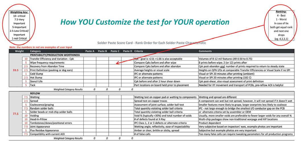
Shea: Contact Practical Components. They should send you a documentation package. What is in that package right now is a list of all the different tests and descriptions, the 25 different tests that are embedded in here, the bill of materials, a sample size calculator, the area ratios and reference designators, the step-bystep solder paste test process, and the scorecard. We haven’t talked about scorecards yet, but that is where you rank paste performance relative to each other and look at each category of reflow, print, testability, supplier value, etc., and determine which paste gives you the best results. When some are categorized, you can say, “I’m going to trade off some reflow properties for better printing and a little response to idle time for better voiding.” You can see that all on the scorecard.
Johnson: There certainly seems to be an increased specialization with respect to what the solder pastes do—what they’re strong in, and what they’re weak in. It’s not a “one paste fits all” industry any longer. Does this test vehicle enable an assembler to characterize their line on all the different pastes they may plan to use or the various process windows, or is there

Shea: I usually advise my clients to contact as many paste suppliers as they want, but then do a down-select to three before they run any final tests. When a user fills in the scorecard, before they put any data in it, they weight how important a particular characteristic is to their operation. Again, there are 20+ characteristics. They know what’s important to them. For example, If they are a low-volume shop, response to idle time is very important to them. If they are a high-volume shop that runs 24/7, idle time is of far less consequence. Once they have determined their needs by heavily weighting their key factors, they can then effectively communicate those needs to the paste suppliers, who better understand the trade-offs in properties and can deliver the best candidate for the application.
I suggest the user choose whatever the most stringent test is and use that for a down-select. If they want to be able to run that first print after an hour, or everything they run goes through pin test, it’s easy to do a down-select there. Then, they take the top two or three and run them against the incumbent. The user ranks the results in the scorecard, which multiplies the rankings by the weights to calculate the individual scores. The user can then see how each paste compares to the incumbent in each characteristic and category. They make an informed, data-driven decision, and as they migrate toward their new soldering chemistry, they are guarded against the gotchas because they’ve already looked at 25 different properties on their assembly line and have a good idea of what to expect.
We’ve run into situations where somebody selects the paste because it’s low on voiding, and they find out it’s not very active, and it doesn’t wet very well, or it has great response to idle but isn’t pin-test friendly. There’s always a trade-off in solder paste. This test method is meant to encompass all the different properties, so the user knows what their trade-offs are right up front before implementing it.
Johnson: An evaluating assembly shop is going to get some answers on if I can achieve the kinds of precision that I want and where my current set-up is failing. Is it the paste or equipment I’m using or the expertise of my operators? It would seem that this will tend to shake out the problem areas for the assemblers.

Shea: Exactly. If they don’t like the reflow results on any of the pastes, maybe they need to go back and revisit their profile. I see this phenomenon all the time, where people use banged up stencils and squeegees. If you go into a test introducing that much noise into it, you’re not going to get very clear results, and I tend to get on a soapbox about tooling because it’s so important. There’s a lot of different things to consider, but you’re absolutely right. You will find your own factory’s strengths and weaknesses.
A lot of my clients test the most popular pastes in the country. I’ve run so many tests on them that by looking at the data off of somebody’s printer or SPI machine, I can tell you whether a particular paste should print that way or not. And using the same test board makes that call even easier.
Johnson: To run this benchmark test, do you need somebody that knows the test well to help you interpret the data?
Shea: I would say no because we tried to make it as easy as possible. This was an effort by myself, Dr. Neil Poole of Henkel—who has over 30 years in being on the floor printing at various different customers—Dr. Mark Currie— who has 25–30 years in paste development and did his Ph.D. in solder paste printing—and Doug Dixon—who is also a 30–35-year veteran of the industry. There were well over 100 years of experience trying to make this simple as possible, and that’s where the step by step comes in. That’s also where the list of tests and descriptions comes in. This should be completely self-manageable; several organizations have run it according to this, and they’ve done absolutely fine with it. You don’t need an expert. That said, I’d be happy to help you for a certain fee (laughs), but you can do this all on your own.
Johnson: What else can we use this board for?
Shea: Many people need to demonstrate capability for the next package size down, which for a lot of us is 01005, and there’s 800 components or 1600 pads on the board. There’s also 0.4- and 0.3-millimeter devices on the board, as well as 0.4-millimeter BGAs. A lot of assemblers, especially the contract shops, need to show the capability to their OEM before they can start production on these new package types. This demonstrates the assembly process.
Also, because the board is wired out to test points or gold fingers, you can perform reliability qualifications on these new package types as well. We have also used it on multiple occasions to test different stencil designs. And we’ve been using it a lot to develop the print process for the 008004s or 0201 metrics in conjunction with a stencil printer manufacturer and a paste manufacturer. We’re all working together to roll out a process for that.
One of the pieces of feedback I got was from an OEM who said, “Given this kit, I should be able to walk into any CEM at 8:00 in the morning with a box of parts and a jump drive of files, and if they’re not running by noon, they’re not any good.” We’re using it to benchmark SPI and AOI equipment. Also, we have IPC placement rates and other placement rates. I’m aware of at least one company that’s taking this board to the different placement manufacturers to see how close their placement rates are to published data and what’s going to be the best for their operation.
Johnson: It sounds like there is plenty of opportunity for this board to be used as a testbed.
Shea: Yes, for all kinds of things. Hopefully, it will become a more mainstream universal test vehicle for the next few years. And when we need to put a smaller component on, I’ll be happy to spin the artwork. That’s what makes it fun.
Johnson: Fantastic. Chrys, thank you for your time.
Shea: It’s my pleasure. SMT007


