13 minute read
High-reliability, Low-temperature Solder Alloys
from Croll6e
by Thomas Swift
Feature by Pritha Choudhury, Morgana Ribas, Raghu Raj Rangaraju, and Siuli Sarkar
MACDERMID ALPHA ELECTRONICS SOLUTIONS
Advertisement
Increased digitalization and greater connectivity have been driving miniaturization and more complex and integrated designs in electronics. As the real estate on PCBs shrinks, so does the size of packages. However, the drive for finding design solutions for increased performance has continued to expand. The solder joint is an essential part of assemblies for electronic devices as it provides electrical, thermal, and mechanical connections. Therefore, soldering materials have been evolving to enable such a technological revolution.
Restrictions in using lead in soldering materials in the early 2000s have propelled the electronics industry towards the widespread use of lead-free soldering materials. Since then, the requirement for solder alloys with higher thermal and mechanical reliability is the most important technology driver for designing new soldering materials. Low-temperature solders (LTS) are currently being considered for a variety of assembly needs. They have the potential to increase long-term reliability by reducing thermal exposure, to reduce overall materials cost by using low-Tg PCBs and low-temperature compatible components and its carbon footprint. Using low-temperature solders has also been shown to lower energy consumption, to reduce dynamic warpage of BGA packages and PCBs, to increase assembly yields, and to lower or eliminate non-wetting open and head-on-pillow defects [1, 2] . Indeed, dynamic warpage is a serious concern for PoP bottom and PoP memory packages, as they can cause serious soldering defects, such as non-wet opens, solder bridging, headon-pillow, and non-contact opens [1, 3]. Extensive studies have shown that such warpage is highly dependent on the reflow temperature and can be drastically reduced to acceptable levels by keeping the soldering temperature below 200°C [1] .
It is important to note that just reducing the melting point of an alloy is not enough for delivering high-reliability solutions for such technical challenges. For example, the eutectic 42Sn58Bi alloy would be a logical choice, given its melting point at 138°C, but its lower ductility and poor thermal fatigue life do not come close to the currently used SAC305 alloy. Its Bi-rich phase causes embrittlement, making eutectic 42Sn58Bi prone to brittle fracture under high strain rate conditions [4]. Materials suppliers and industry consortia, such as iNEMI, have been extensively working on developing and testing new low-temperature alloys to fulfill such requirements [5–11] .
The addition of silver has been one of the most common ways to modify the microstructure and resulting properties of the eutectic SnBi alloy. MacDermid Alpha Electronics Solutions’s extensive research on solder alloys went beyond that and worked on developing a comprehensive family of low-temperature solders with improved thermal and mechanical reliability. SBX02 solder (an Ag-free eutectic SnBi with micro-additives) has been shown to have significantly higher mechanical shock and thermal cycling properties than commonly known 42Sn58Bi and 42Sn57.6Bi0.4Ag alloys [8]. More recently, HRL1 (a non-eutectic SnBi solder with about 2 wt.% performance additives) has shown superior drop shock and thermal cycling performance. This new LTS alloy combines an optimal level of Bi and the right combination of alloying additions to improve its thermal and mechanical reliability, as shown herein.
LTS Paste and Assembly
The selected alloys were processed into IPC type 4 powders and mixed into a paste using an appropriate paste flux for further solder joint thermal and mechanical reliability evaluation. The reflow profile used for assembling the test vehicles with HRL1 solder paste is shown in Figure 1. Soaking was done at 100–120°C for 60–90 seconds. The time above liquidus (TAL) was 35–40 seconds, while the peak reflow temperature was 185–190°C. All the BGAs evaluated had SAC305 balls.
Bulk Alloy Properties
A combination of solid solution strengthening and precipitation/dispersion hardening can be used to improve the mechanical strength of metallic Sn. Elements such as Bi, In, and Sb have relatively high solubility in Sn, forming a solid solution, whereas other elements such as Ag and Cu have little solubility in Sn-Bi and, among other elements, can be used in minor additions for their strengthening. Bulk alloy properties can provide insightful information about solder joint mechanical and thermal fatigue resistance, going beyond the microstructure observations. Table 1 shows some key physical properties of eutectic 42Sn58Bi, HRL1, and SAC305 alloys. Solidus and liquidus temperatures of high purity 42Sn58Bi alloys are identical (i.e., eutectic) and about 138°C. As per the Sn-Bi phase diagram, reducing the Bi content below the 58 wt.% corresponding to the eutectic point, results in higher liquidus temperature, depending on microalloying additions. In the case of alloy HRL1, the solidus and liquidus temperatures are Figure 1: Reflow profile for the HRL1 low-temperature solder. 138°C and 151°C, respectively.
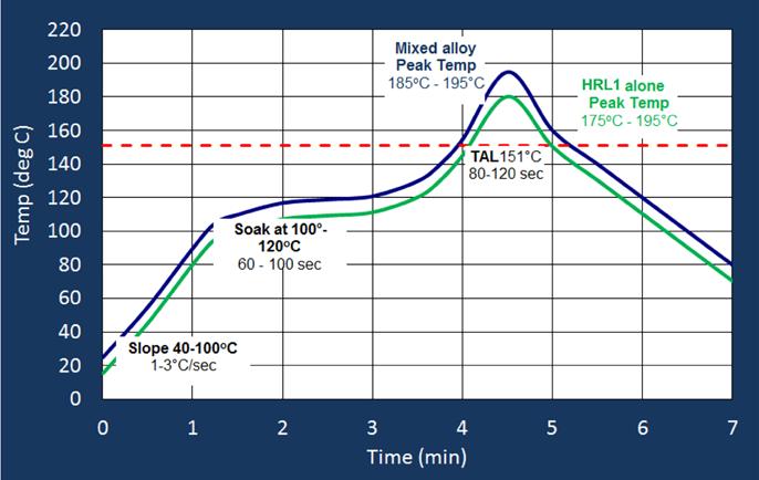
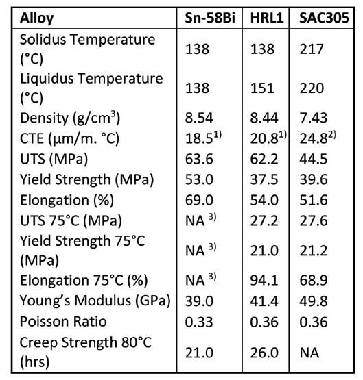
Table 1: Key bulk alloy properties. (Notes: 1) CTE between 25 and 80°C, 2) CTE between 25 and °C, 3) Sample deformed at °C. strong indication of HRL1 improved mechanical and thermal strength.
Creep tests of the bulk alloys were performed using a constant load (150 N) at 80°C. This type of test offers an opportunity for gauging the thermo-mechanical properties of solder joints before any assembly takes place. The total time until rupture, also called creep strength, of HRL1 is 30% higher than in the eutectic 42Sn58Bi, providing additional evidence of HRL1 improved resistance to mechanical and thermal stresses.
Mechanical and Thermal Reliability
Portable and handheld devices have quickly become part of our daily lives and, consequently, resistance to drop and shock turned into a must-have property of solders used in such devices. Since the testing of actual electronic devices is quite cumbersome and expensive, proxy tests (such as the JESD22-B111 standard) can be used instead. JEDEC’s service condition B (1500 Gs, 0.5 ms duration, and Additionally, the DSC curve of HRL1 shows a half-sine pulse) is probably the most common 79.7% conversion into a liquid at 139°C and drop shock test at the board level and serves as 99% at 144°C [10]. The densities of 42Sn58Bi a reference for the results presented later. and HRL1 alloys are higher than SAC305, as Bi Reducing the Bi content below 58 wt.% density is considerably higher than Sn. The lin- can effectively improve the alloy ductility ear coefficient of thermal expansion (CTE) of while maintaining its strength and results in HRL1 alloys is somewhere in between 42Sn58Bi improved drop shock performance, as shown and SAC305. in Figure 2 [10]. However, Sn-Bi alloys with 40
At room temperature, both Sn-Bi alloys have wt.% Bi or lower have liquidus temperatures considerably higher ultimate tensile strength above 178°C and would require reflow tem(UTS) than SAC305. However, HRL1 alloy yield strength and elongation are similar to those of SAC305. Comparatively, the eutectic 42Sn58Bi higher yield strength exemplifies its brittle nature. Tensile data of 42Sn58Bi at 75°C is not available, as the tensile samples started deforming and slipping from the testing grips. However, at 75°C, HRL1 tensile and yield strength still match SAC305 performance, which is a Figure 2: Weibull distribution of drop shock failures of various LTS alloys using CTBGA84.
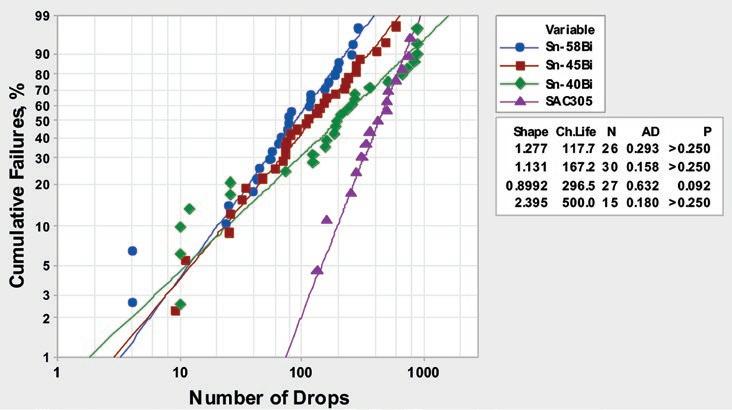
peratures above 200°C, which would defeat the purpose of using a low-temperature alloy in lieu of SAC alloys. Besides that, reducing Bi content from 58 to 40 wt.% increases the drop shock characteristic life (i.e., 63.2% cumulative failures) in 77%, but such performance is still 40% lower than the requirement for a SAC305 drop-in replacement.
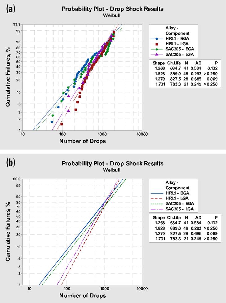
Among dozens of Sn-Bi alloys with various combinations of additives, it was found that HRL1 had the best drop shock performance for both hybrid and homogenous joints, as shown
in Figure 3. The Weibull distribution plots show that HRL1 alloy/SAC305 hybrid solder joints drop shock characteristic life is 82.7% of SAC305 homogeneous solder joints in the BGA84. The LGA84 is used as a quick method to evaluate the drop shock behavior of homogeneous solder joints. In this case, HRL1 alloy drop shock characteristic life is slightly higher than SAC305. In each case, HRL1 and SAC305 Weibull curves are within the 95% confidence interval. It is also interesting to note that the shape parameter for HRL1 and SAC305 are identical for the BGA84 (1.27) and almost identical for the LGA84 (1.83 and 1.73, respectively). A plot of the respective distribution fits without plotting the symbols, as shown in Figure 3 (b), highlights the aspects discussed previously. Thermal reliability tests were performed using a single zone air-air thermal shock chamber, where the samples cycled from -40 to +125°C, with 10 minutes dwell time at each temperature up to 2,000 cycles. The electrical resistance of the components was continuously monitored, and failures were defined as an increase of 20% or more in electrical resistance for five consecutive readings, as described in the IPC 9701-A standard. Figure 4 shows accumulated failures after 1,000/1,500/2,000 thermal cycles. For the in-situ monitoring, only hybrid LTS/SAC305 solder joints were considered while compared to SAC305 joints. No failures were observed Figure 3: Probability plot of BGA84 drop shock failures. (a) Data point symbols in the first 1,000 cycles. and Weibull distribution fit and (b) Weibull distribution fit omitting symbols. After 1,500 cycles, failures

responding degradation (if any) due to thermal cycling. Figure 5 shows a few examples of as-soldered hybrid HRL1/SAC305 solder joints (BGA432, BGA208, and BGA84) and HRL1 homogeneous solder joints (LGA256, MLF100, and chip resistors 1206, 0805 and 0201). For optimized assembly and reflow Figure 4: Thermal cycling accumulated failures on hybrid LTS/SAC305 BGA84 solder joints. conditions, and considering the size of these packages, warpage or soldering defects were not observed. quickly accelerated for the eutectic Sn-Bi alloy, Figure 6 shows the cross-sections of (a) while HRL1 closely followed SAC305 behavior BGA84 solder joints after 1,500 thermal cycles until 2,000 cycles. and (b) chip resistors 1206 after 2,500 thermal cycles. Hybrid eutectic SnBi/SAC305 Solder Joint Evaluation solder joints show higher degradation than
While in-situ monitoring of solder joint elec- hybrid HRL1/SAC305 solder joints, after 1,500 trical resistance provides quantitative infor- cycles. Cross-sections of chip resistors 1206, mation of what happens to the solder joint from a separate thermal cycling test, show during thermal cycling, the analyses of cross- that after 2,500 cycles, HRL1 homogeneous sections provide visual reference of the cor- solder joints have little degradation. Compar-
Figure 5: Examples of cross-sections showing (a–c) hybrid HRL1/SAC305 solder joints and (d–h) HRL1 homogeneous solder joints. Images taken at various magnifications, as indicated in the respective image.
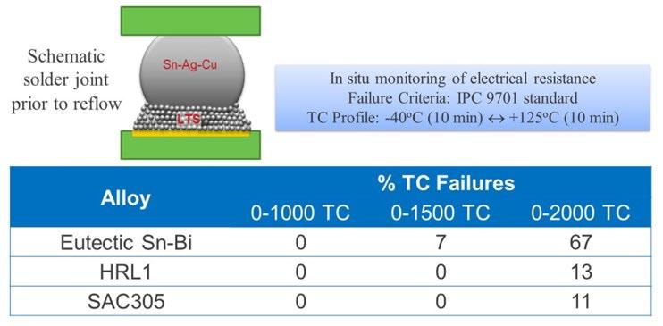
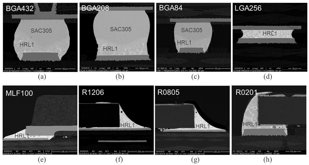
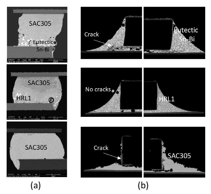
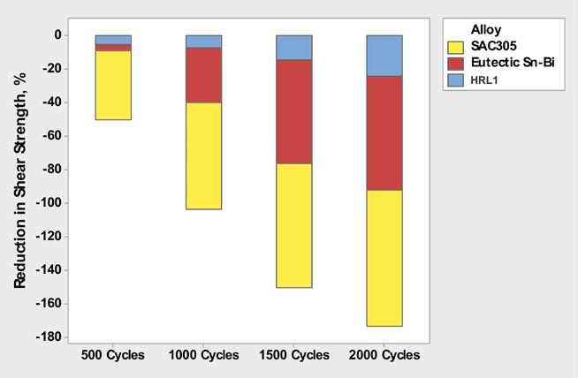
Figure 6: Cross-sections of (a) BGA84 solder joints after 1,500 thermal cycles and (b) chip resistors 1206 solder joints after 2,500 thermal cycles. At 500 cycles, the shear strength of the eutectic SnBi and HRL1 has only a small decrease from their initial values of 10.6 and 11.2 kgf, respectively, whereas SAC305 loss in shear strength is eight times higher. After 2,000 cycles, HRL1 shear strength is 24% lower than its initial value, whereas the eutectic SnBi is 68.4% lower, and SAC305 is 81% lower (from its initial value of 10.1 kgf).
Summary
Given the growing demand for high-reliability, low-temperature, lead-free solder alloys that can be reflowed below 200°C, the alloy characteristics—including melting behavior, microstructure, and thermomechanical properties—need to be carefully considered. For the packages and experimental conditions discussed, the results shown here can be summarized as follows:
Figure 7: Effect of thermal cycling on shear strength.
atively, extensive cracks are observed in SnBi and SAC305.
For these testing conditions and components, all three alloys show a reduction in shear strength after thermal cycling (Figure 7), but HRL1 microstructure seems to withstand better the strains due to stress from thermal cycling. • HRL1 solder combines the higher tensile strength of SnBi alloys with yield strength and elongation similar to SAC305. • HRL1 solder enables peak reflow temperatures as low as 185–190°C for assembling BGA packages with Sn-Ag-Cu balls (i.e., hybrid solder joints), or 170–175°C for homogeneous HRL1 solder joints. • HRL1’s drop shock and thermal cycling performance enables its use as a drop-in replacement for the test vehicles and experimental conditions shown here, and on a variety of other applications.
Acknowledgments
We thank our colleagues at the India R&D Centre for their key support for this work. We
are also grateful to other colleagues that participated in the discussion of the work from which this manuscript is derived. SMT007
References
1. Aspandiar, R., Byrd, K., Tang, K. K., Campbell, L., and Mokler, S., “Investigation of Low-temperature Solders to Reduce Reflow temperature, Improve SMT Yields and Realize Energy Savings,” Proceedings of IPC APEX EXPO, San Diego, California, February 2015. 2. Osgood, H. R., Geiger, D., Pennings, R., Biederman, C., Jiang, J., and Bernal, J., “Low-Temperature SMT Solder Evaluation,” Proceedings of IPC APEX EXPO, San Diego, California, January 2019. 3. Loh, W. H., and Fu, H., “Package-on-Package Warpage Characteristics and Requirements,” SMT Magazine, July 2016, pp. 68–76. 4. Mokhtari, O., and Nishikawa, H., “Coarsening of Bi phase and intermetallic layer thickness in Sn-58Bi-X (X = In and Ni) solder joints,” Proceedings of the 14th International Conference on Electronic Packaging Technology, pp. 250–253. 5. Fu, H., Aspandiar, R., Chen, J., Cheng, S., Chen, Q., Coyle, R., Feng, S., Krmpotich, M., Lasky, R., Mokler, S., Radhakrishnan, J., Ribas, M., Sandy-Smith, B., Tang, K. K., Wu, G., Zhang, A., and Zhen, W., “iNEMI Project on Process Development of BiSn-Based Low-Temperature Solder Pastes,” Proceedings of the 2017 SMTA International Conference, Rosemont, Illinois, September 2017, pp. 207–220. 6. Fu, H., Radhakrishnan, J., Ribas, M., Aspandiar, R., Byrd, K., Chen, J., Cheng, S., Chen, Q., Coyle, R., Feng, S., Hardin, B., Krmpotich, M., Mokler, S., Sandy-Smith, B., Tang, K. K., Wu, G., Zhang, A., and Zhen, W., “iNEMI Project on Process Development of BiSn-Based Low-Temperature Solder Pastes–Part III: Mechanical Shock Tests on POP BGA Assemblies,” Proceedings of the 2018 International Conference on Electronics Packaging, Kuwana, Japan, April 2018. 7. Fu, H., Radhakrishnan, J., Ribas, M., Aspandiar, R., Arfaei, B., Byrd, K., Chen, J., Cheng, S., Chen, Q., Coyle, R., Daily, D., Feng, S., Krmpotich, M., Mokler, S., Sandy-Smith, B., Tang, K. K., Wu, G., Zhang, A., and Zhen, W., “iNEMI Project on Process Development of BiSn-Based Low-Temperature Solder Pastes–Part IV: Comprehensive Mechanical Shock Tests on POP Components Having Mixed BGA BiSnSAC Solder Joints,” Proceedings of the 2018 SMTA International Conference, Rosemont, Illinois, October 2018. 8. Ribas, M., Hunsinger, T., Cucu, T., Ramakrishna, H. V., Lim, G., and Murphy, M., The Printed Circuit Assembler’s Guide to...Low-Temperature Soldering, BR Publishing Inc., 2018. 9. Ribas, M., Vangapandu, B., Rangaraju, R. R., Telu, S., Pai, L., Kumar, R., Patil, V., Ramakrishna, H. V., Cucu, T., and Sarkar, S., “Low-Temperature Soldering: Reflow Optimization for Enhanced Mechanical Reliability,” Proceedings of the 2018 SMTA International Conference, Rosemont, Illinois, October 2018. 10. Ribas, M., Kumar, A., Kosuri, D., Rangaraju, R. R., Choudhury, P., Telu, S., and Sarkar, S., “Low-temperature Soldering Using Sn-Bi Alloys,” Proceedings of the SMTA International Conference and Exhibition, Rosemont, Illinois, September 2017. 11. Ribas, M., Augustine, P., Choudhury, P., Rangaraju, R. R., Kumar, A., and Sarkar, S., “Low-Temperature Soldering: Thermal Cycling Reliability Performance,” Proceedings of IPC APEX EXPO, San Diego, California, January 2019.
Dr. Pritha Choudhury is sr. scientist of R&D at MacDermid Alpha Electronics Solutions.
Dr. Morgana Ribas is a sr. R&D manager of the Metals Technology Group at MacDermid Alpha Electronics Solutions.
Raghu Rangaraju is a R&D scientist at MacDermid Alpha Electronics Solutions.
Dr. Siuli Sarkar is director of R&D, India Research Centre at MacDermid Alpha Electronics Solutions.
All the authors are located at the MacDermid Alpha Electronics Solutions India Research Centre, Bangalore, India.
