


Water Treatment, Optimised

Water Treatment, Optimised
Thornton Tomasetti’s bespoke computational fluid dynamics (CFD) methods provide specialist analysis for the design of water treatment equipment and systems.
Our services include:
Clean Water Applications
• Reservoirs
• Contact Tanks
• Service Reservoirs
• Ozone Tanks
• Ultraviolet Disinfection
• Pump Sumps
• Surge Analysis
• Network Modelling/Flow Distribution
Wastewater Applications
• CSOs/Storm Tanks
• Primary Tanks
• Anaerobic Digesters
• Flow Load Balancing
• Aeration Lanes
• Anoxic Zones
• Final Settlement Tanks
• Phosphorous Removal
• DSEAR (Dangerous Substances & Explosive Atmospheres) Assessments
• Surge Analysis
We help clients optimise their assets with minimal disruption and expenditure.
Some of our Clients:
• A&J Fabtech
• Aquafin (Belgium)
• Atkins
• Black & Veatch
• Chemineer
• Grontmij
• Hyder
• Imtech
• Meica Process
• MWH Global
• MWH Treatment/Biwater
• NMC Nomenca
• OVIVO/Tamesis
• Pick Everards
• Purac
• Severn Trent Water
• Southern (4D)
• South West Water
• Thames Water
• United Utilities
• Veolia Water (Scotland & NI)
• Welsh Water (Dwyr Cwmru, Kelda)
• Wessex Water
• Yorkshire Water
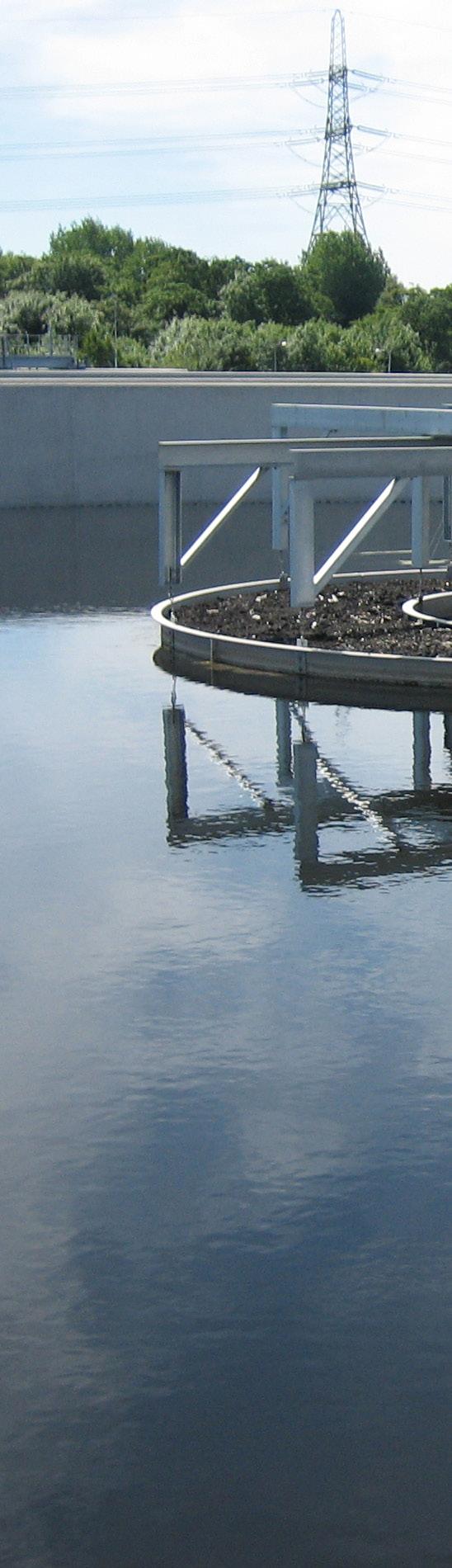
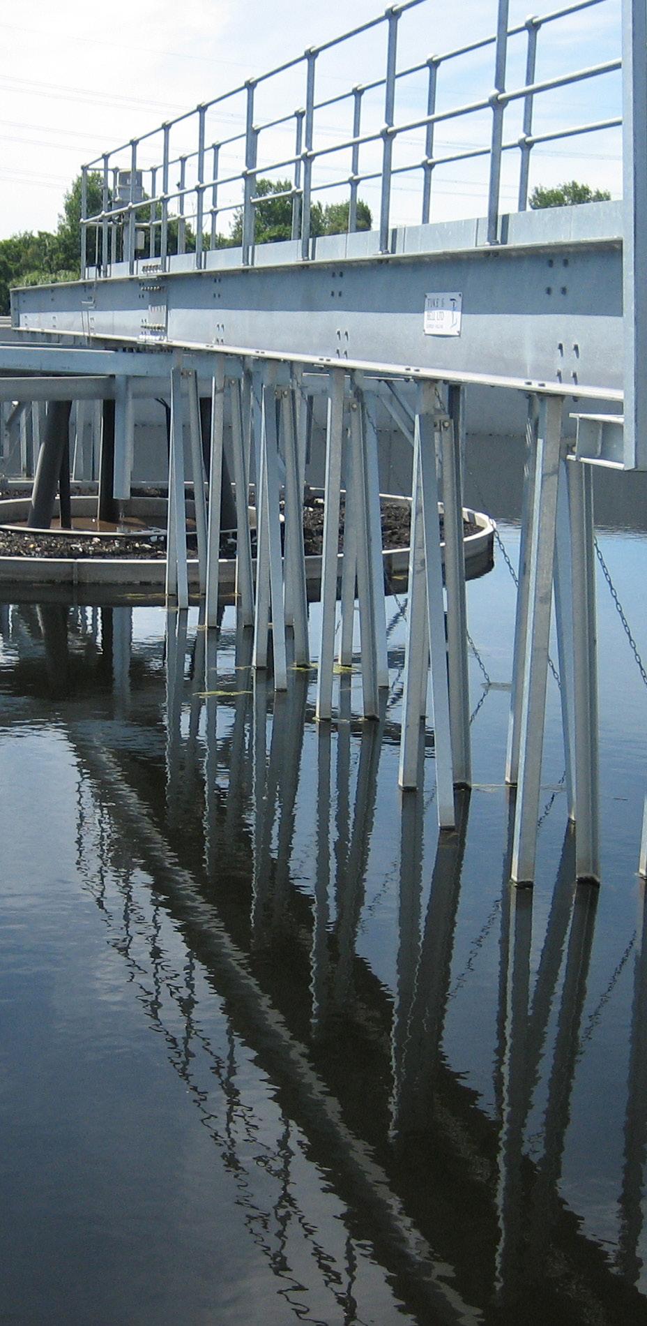
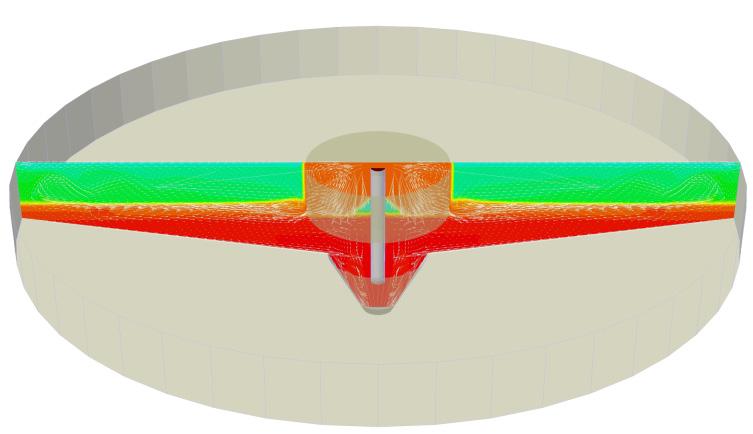
Many reservoirs and water treatment works (WTW) within the UK are adjacent to farmland.
This means there is a possible risk of cryptosporidium or other pollution within these water supplies during periods of heavy rainfall.
We are experienced in the successful application of flow modelling techniques across a range of process industries. In particular, our experts have applied CFD methods to model the dispersion and convection of contaminants in reservoirs. This enables us to highlight important flow features such as recirculation zones, shortcircuiting and flow stagnations.
Our engineers have developed a risk assessment method for quantifying the impact of a cryptosporidium release event. Response curves at reservoir offtakes can be monitored in the model with respect to potential releases from coastal sources. The model can provide the WTW plant operators with detailed information on peak arrival time, peak concentration, dilution factors and mixing effectiveness. We can then anlayse this information to determine which release points pose the greatest risk and quantify the relative magnitude of this risk.
While bubble barriers are commonly used to disperse algal blooms, they can also be positioned to effectively screen the treatment works and provide dilution and dispersion of cryptosporidium oocysts.

Surface flow patterns for reservoir in normal flow conditions.
A good contact tank design depends on its ability to promote plug flow.
Plug flow provides water of uniform treatment quality to a domestic water supply. We use CFD techniques to generate detailed information about flows, residence time distribution (RTD) and chlorine degradation in water treatment systems.
We generate the basic hydrodynamics from a 3D model of the tank’s geometry, with boundary conditions applied to represent inflows, outflows and the presence of internal baffles. A simple age scalar can be used to emphasise the presence of flow recirculation and quiescent regions.
Dye trace studies can be replicated in a CFD calculation and used to compare designs via different indices that define mixing characteristics, such as t10, and the number of tanks in series.
We can also calculate the transport of a disinfectant such as chlorine and include a decay model to determine, for example, the amount of residual chlorine at the discharge from the contact tank.
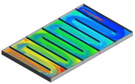
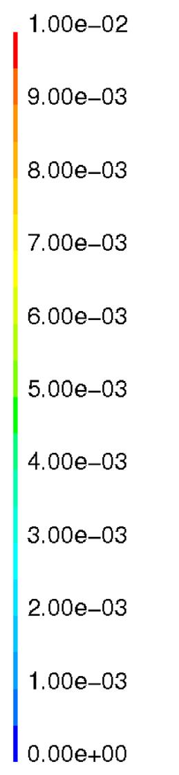
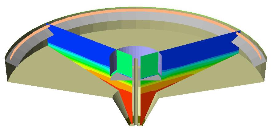
A rectangular service reservoir with baffles explicitly modelled. An age scalar is used to show the youngest water jetting in (blue) and the oldest water gathering (red) in the slower moving regions.
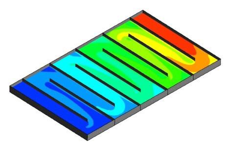
Chlorine concentration. Note how the oldest water (see Figure 1) corresponds with the region of lowest chlorine.
UV sources are increasingly used to kill pathogens – including cryptosporidium oocysts – in drinking water.
Although target dose rates can be specified, it is difficult to design configurations of UV tubes that guarantee full effectiveness.
We have worked with UV equipment manufacturers and water companies to improve dosing performance. Due to the rapid throughput and short residence time, any reduction in hydraulic performance away from plug flow (dead zones or poor distribution) has a significant influence on overall performance. We have developed a CFD modelling technique that can assess the dose given to a water stream and to compare and optimise UV treatment.
We combine 3D geometry, flow conditions and fluid properties to solve the Navier-Stokes fluid flow equations to determine the flow distribution. Next we calculate the UV radiation field distribution. Then we track fluid stream lines through the flow and compute cumulative UV radiation dose to the stream.
The base flow information is augmented with UV dose data to give the designer a pictorial view of problem areas. UV dosage can also be quantified in a histogram of the total flow, useful for comparing design alternatives.
We have conducted modelling investigations for clients on flow and dose rate, and designed several modifications, including:
• Chamber geometry
• UV tube layout & power
• Upstream & downstream geometry
• Inflowing water properties
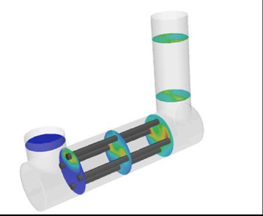
A contour plot of cumulative UV dose on water.
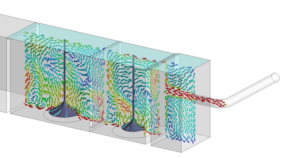
The efficiency of a pump is affected by the hydrodynamics of the approaching flow.
This is due to the pump’s impellers, which are designed with the assumption that the flow will approach axially. Examples of non-ideal flow conditions include:
• Pre-swirl of the flow
• Free surface vortex formation
• Submerged vortex formation
• Spatial asymmetry of the flow
• Temporal fluctuations (turbulence) in the flow approaching the pump impeller
We use CFD modelling techniques to confirm new designs or optimise existing pump sumps to meet performance requirements, including:
• No organised free surface and/or subsurface vortices of greater magnitude than Type 2 shall enter the pump
• The level of pre-swirl should be steady and less than five degrees from the axial direction
• Time-averaged velocities measured at eight locations in the pump throat should be within ± 10% of the spatial mean of time-averaged velocities
• Temporal fluctuations of velocities measured at each of the eight locations should be less than 10% of the average velocity measured at that location
Streamlines showing non-uniform approach flow in a series of pump bays.
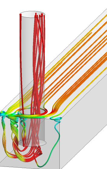
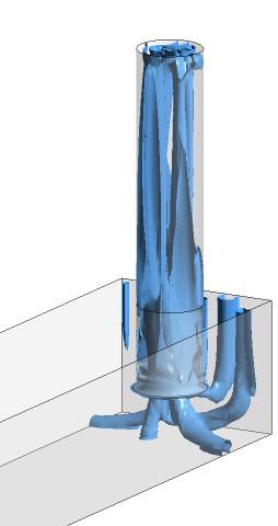
of free-surface & submerged vortex structures.
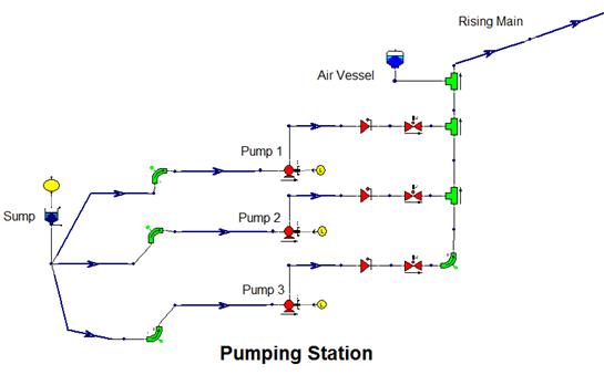
We use computational pipe network models for surge analysis to determine transient pipeline pressure.
Surge protection is typically achieved through surge vessels on the suction and delivery side of pumps. As part of a surge analysis, our experts define the volume, dimensions and connection details to the rising main. We also design more bespoke systems that use surge-relief valves or pressure-sustaining valves and utilise existing equipment. This keeps transient pressures from exceeding the pipeline rating and dropping below atmospheric pressure, which could result in ground-water ingress.
Our surge analysis team are highly experienced in the use of surge analysis software packages to solve problems associated with equipment operation, such as pump start-up/stop trip, valve actuations and pipe failures.
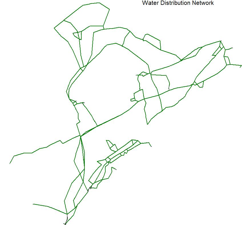
Computational analysis forms an essential part of water distribution network management.
CFD methods can identify operational issues, such as shortfalls in supply or depleting reservoir levels.
And we can use the same analysis techniques to optimise operation and cost, as well as the design of network extensions.
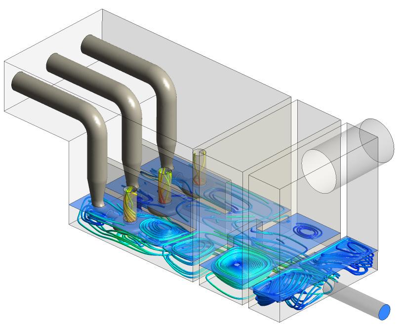
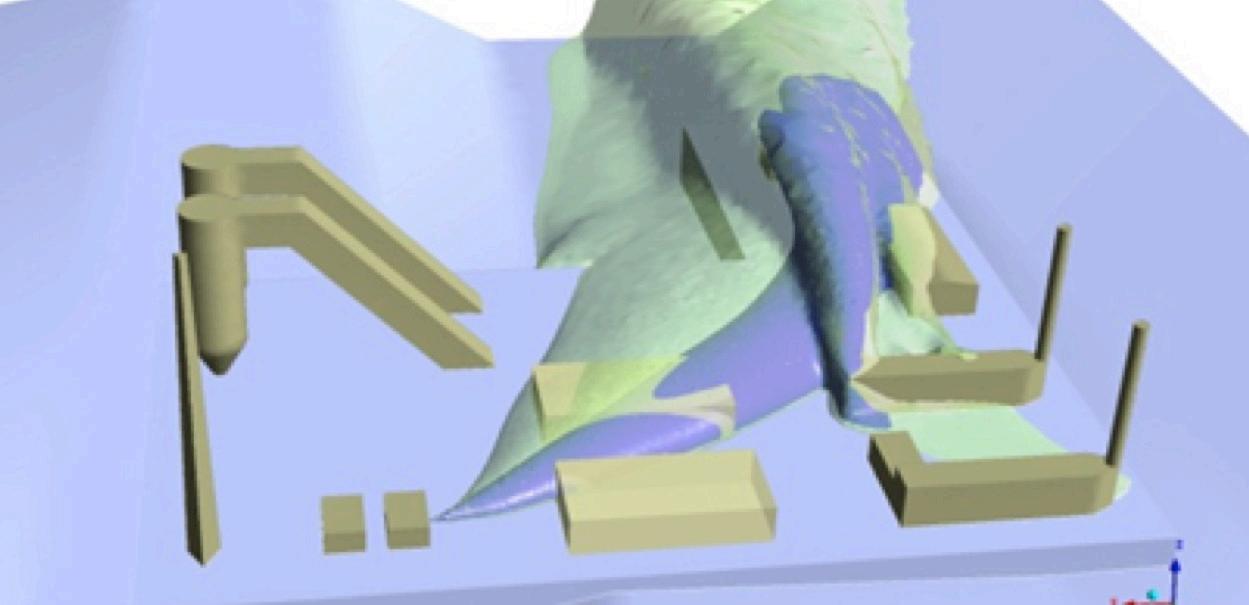
CSOs are used to spill storm water during heavy rainfall. Storm tanks act as a source of capacitance, storing storm water until the storm load subsides.
Both systems should allow the flow to spill with minimal loss of solids. Our team uses CFD to assess the effectiveness of a CSO or storm tank at retaining solids. We also undertake preliminary assessments of vac flush systems used for flushing solids from storm tanks and hydroejectors that homogenise solids during drain down.
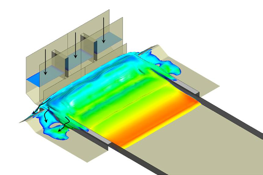
Example of a fluid release into the storm tank during vac flushing.
Primary tanks are used to remove the majority of settleable solids from raw and screened wastewater. Solids sludge is usually passed forwards to digesters; the settled sewage goes on to secondary treatment.
We use CFD simulation techniques to assess the internal hydro-dynamic performance of settlement tanks to assess the settling performance of an existing or new tank design and to optimise the effluent quality by improving tank geometry or the inlet arrangement.
Anaerobic digesters are increasingly used at WTWs for a number of reasons.
They reduce the need for solid waste removal, lower energy costs by means of onsite power generation from the biogas produced, and decrease carbon emissions.
Digester sludges, usually a blend of primary and surplus activated sludges, behave as a non-Newtonian fluid, so we use a Heschel-Bulkley model to analyse its behavior. Mixing systems using gas or mechancial mixing or external pumping provide a homogenous blend of sludge and bacteria at a near constant temperature. We apply a Eulerian-Eulerian approach for gas mixing, using drag models for the fluid-gas interaction.
To ensure the sludge has the desired residence time in the tank, a dye trace study can generate a residence time distribution. Our simulations can confirm the effectiveness of an anaerobic digester design without the need for expensive testing.
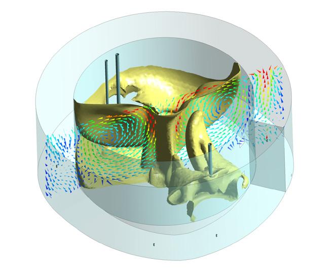
Feed sludge in the inner tank of an acid phase digester passing to the outer tank with a good degree of mixing.
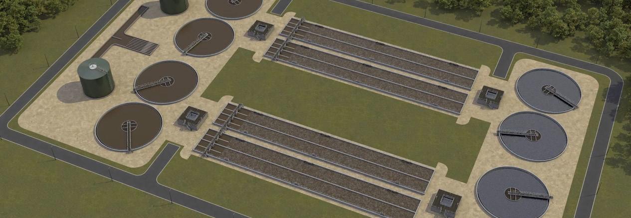
Civil engineering structures are used to distribute the flow and solids load to multiple settling tanks or aeration lanes at a sewage treatment works.
Achieving a good fluid and solids distribution ensures equal loading on settlement tanks/aeration lanes and is fundamental to achieving optimal treatment performance.
We use CFD to assess the flow and solids distribution using appropriate multiphase models to resolve free-surface effects, which influence fluid distribution, and accurate simulations for tracking the solids load.
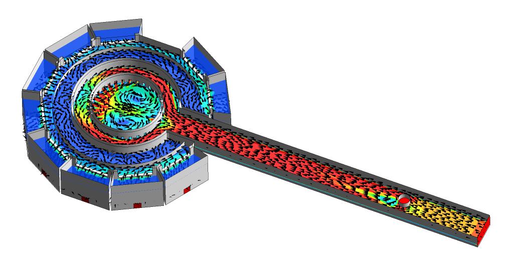
Flow/load balancing.
CFD enables accurate assessment anoxic zones and aeration lanes, including the performance of aerators within the lanes.
Our CFD methods allow resolution of impeller action on the flow and solids distribution, while dye trace studies that use CFD can determine residence time and degree of short circuiting.
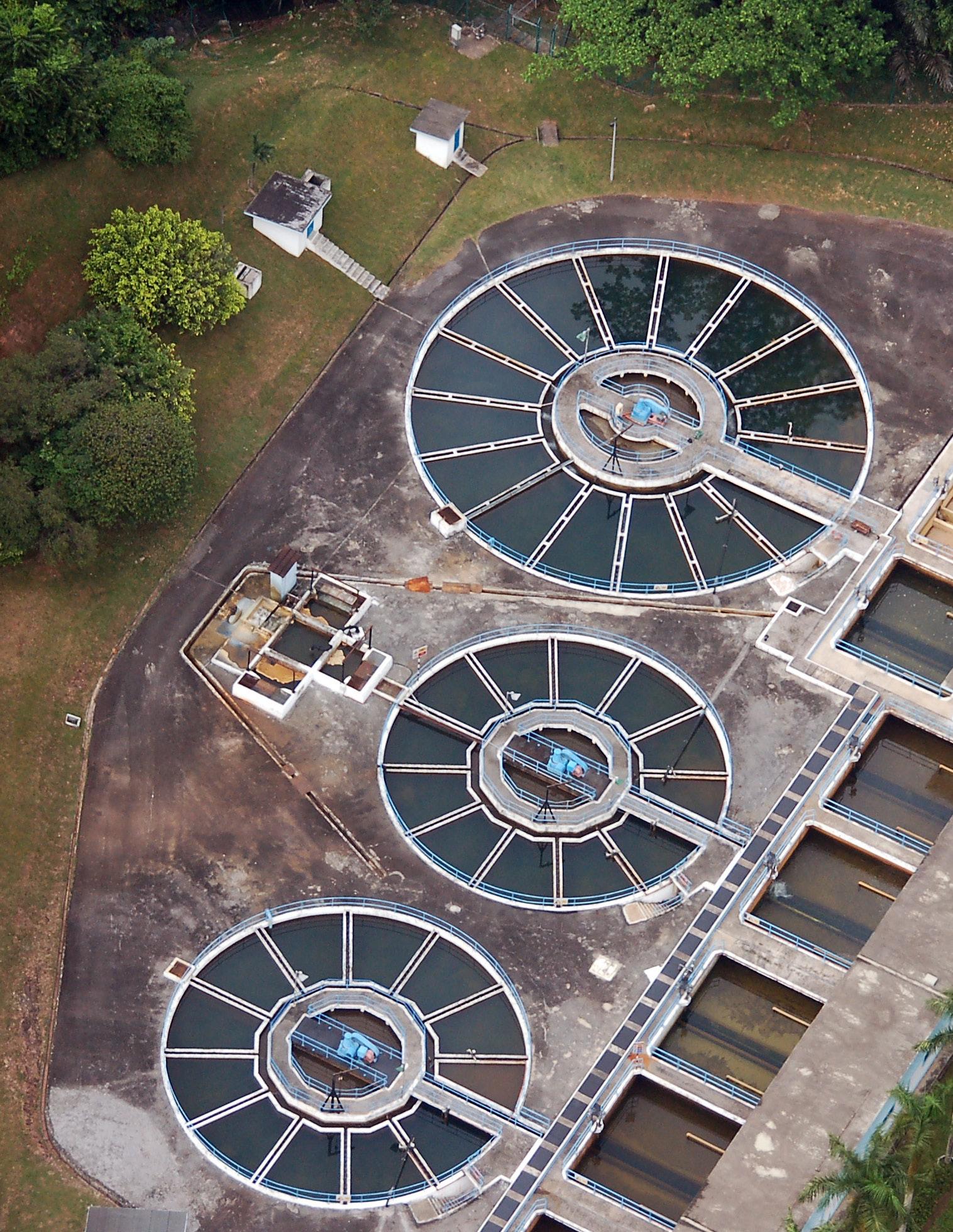
Final settlement tanks clarify the final effluent at activated sludge plants.
The flow through a final tank is not one-dimensional and will exhibit non-ideal flow behavior, such as flow recirculation and short circuiting, so the actual settling performance will usually be less than predicted by mass flux theory (MFT).
CFD can be used to assess the internal hydrodynamic performance of existing or new tank designs. We can opitimise tank geometry or the inlet arrangement – by inclusion or adaptation of stilling wells; energy dissipation influents; or baffles, such as the McKinney baffle – to improve effluent quality.
Since the Urban Wastewater Treatment Directive of 1991, UK water companies have had to manage phosphorus discharges. The target level for phosphate is below 0.1mg/L.
The growing interest in renewable sources of phosphorous and beneficial reuse applications has increased the range of phosphorous removal options available, making the evaluation process quite complex.
Our approach to phosphorous reduction involves the following steps:
• Evaluate the treatment process
• Identify phosphorous removal options
• Evaluate sludge handling & disposal practices
• Evaluate removal options using biological simulation software
• Prepare cost estimates
Options for phosphorous removal include:
• Biological phosphorous removal
• Controlled struvite formation & capture
• Chemical phosphorous removal
• A combination of the above
Solids separation can have a significant impact on the success of phosphorous removal technologies, since effluent limits are generally on a total phosphorous (TP) basis, rather than a soluble basis. Very low soluble phosphorous concentrations can be achieved through a combination of technologies, but the phosphorous associated with the solids means that the solids must be separated and captured.
Our expertise in improving solid-liquid separation using proprietary modelling and CFD techniques can optimise existing settlers and minimise capital investment.
Dangerous Substances and Explosive Atmosphere Regulations (DSEAR) require employers to specify the dangerous substances in their workplace.
Employers must also assess the consequent fire and explosion risks of dangerous substances. In the water industry, this might include chlorine gas, methane or hydrogen sulphide.
We can apply our our extensive experience in DSEAR to help employers with compliance, by assessing the hazardous properties of substances associated with on-site processes and analysing their risks.
Dispersion analysis can determine worst-case gas cloud volumes following the release of a flammable substance and the regions affected by hazardous concentrations of gases. Explosion modelling assesses the potential consequences.
Hazardous area classification is the process of grading hazardous zones from a scale of worst-case to least onerous. Protective equipment must be selected in accordance with the requirements contained in the Equipment and Protective Systems Intended for Use in Potentially Explosive Atmospheres Regulations of 1996. Employers are required to provide training to those at risk if a dangerous substance is present; our team has the expertise to assist with this training.
Biogas is generated during anaerobic digestion and there is the potential for methane and hydrogen sulphide to accumulate. This poses a number of risks, as methane is flammable and hydrogen sulphide is both flammable and highly toxic, even at low concentration.
Contact us to learn more: Anna Duda, PhD, MSc, AMIMechE ADuda@ThorntonTomasetti.com +44.11.7313.7480

Thornton Tomasetti is an international firm of creative problem solvers combining expertise from a range of disciplines to create lasting solutions for complex challenges. Our engineers, architects, scientists, and sustainability experts collaborate from offices worldwide to help you achieve your goals.
www.ThorntonTomasetti.com