2 minute read
an Off Axis Angulation: An Engineering Perspective


By Dr. Robert Dobrin
Modern dental implants integrated with the underlying bone must connect to functional prosthetic restoration. Historically, the connection would be either a cemented restoration with an intervening abutment or a screw-retained connection. It has been observed that complete cement removal from a cement-retained crown is challenging, and any remaining cement is likely to cause periimplantitis, which could lead to implant failure1. To prevent this problem, some clinicians use screw retention wherever possible. The prosthetic challenge with screw retention is the location of the access channel. Frequently, a straight line through the center of an implant will place the access hole in an esthetically or prosthetically compromised position. To overcome this problem, abutments were developed where the screw connecting the abutment to the implant is in line with the implant. A second hole was placed at an offset angle more favorable to the prosthetics. There are situations when it is preferable to have a direct screw connection without an intervening abutment, so screw systems were developed that allow screws to be driven at angles that are off axis to the implant2
Various implant and abutment system manufacturers publish specifications for the torque required to connect the prosthesis to the implant successfully. The tightening torque is a measure of the clamping force of the abutment into the implant3,4,5,6
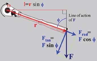
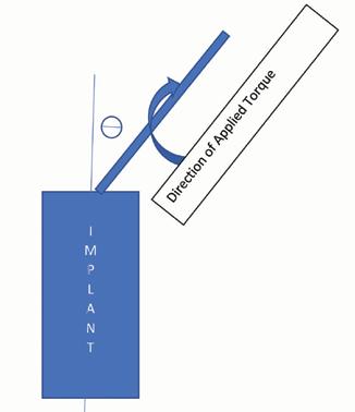
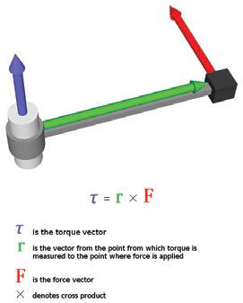
Torque is defined as the product of a force delivered at a distance from a pivot point (Fig. 1). The component of the torque that is delivered along the long axis of the screw is the only torque that serves to tighten the connection. It is reduced when the force is at an angle other than perpendicular to the lever arm. The subsequent force delivered perpendicular to the lever arm can be calculated via vector analysis as the total applied force multiplied by the appropriate trigonometric function of the angles involved, as in Fig. 2. An applied torque can similarly be represented as a vector where the blue arrow represents the torque vector, and vector analysis can be used to determine how much of the torque is being delivered along the long axis of the screw7 (Fig. 3). The torque delivered along the long axis in Fig. 4 with the total torque being delivered off the axis can be calculated as long axis torque = total torque * cosine (O).
From this vector analysis, one can see that when torque is delivered at an angle that is not parallel to the screw insertion direction, the screw tightening force locking the prosthesis to the implant will be reduced. When we place an implant restoration, we need to adjust the applied torque based on the delivery angle, and the implant manufacturers recommended axial torque. t
Torque being applied at an angle other than the long axis of the implant yielding clamping force torque equal to the applied torque times the cosine of the angle between the long axis of the implant and the direction of the applied torque